Automator MB19VP User manual

AUTOMATOR INTERNATIONAL SRL –Via Meucci n.8–20094 Corsico (Mi) Italia
Tel 02 48601445 Fax 02 48601503 e-mail info@automator.com www.automator.com
Tel 02 48601445 Fax 02 48601503 e-mail info@automator. Com www.automator.com
Tel 02 48601445 Fax 02 48601503 e-mail info@automator. Com www.automator.com
Document
INSTRUCTION FOR USE
Code: MAN MBVPREV3
Ediz.n: 4
Del: 03/2012
Pag. 1/26
Edited by: U.T. VB
1.1.1.1.1.1 .
Appr. by: RB.
Machine:
VP UNITS
Document:
Instruction for use
Machine: Pneumatic pneumatic marking units
MB19VP-VPN MB21VP MB35VP
Manufacturer:
Automator International S.r.l. 20094 Corsico (MI) Italy - Via Meucci 8.
AUTOMATOR INTERNATIONAL SRL –Via Meucci n.8–20094 Corsico (Mi) Italia
Tel 02 48601445 Fax 02 48601503 e-mail info@automator.com www.automator.com
Tel 02 48601445 Fax 02 48601503 e-mail info@automator. Com www.automator.com
Tel 02 48601445 Fax 02 48601503 e-mail info@automator. Com www.automator.com
Document
INSTRUCTION FOR USE
Code: MAN MBVPREV3
Ediz.n: 4
Del: 03/2012
Pag. 2/26
Edited by: U.T. VB
1.1.1.1.1.1 .
Appr. by: RB.
Machine:
VP UNITS
INDEX
1 GENERAL DATA ...................................................................................................................4
1.1 GENERAL DATA .................................................................................................................................................4
1.2 WARRANTY.........................................................................................................................................................6
1.3 SYMBOLS REFERRED TO THIS MANUAL.......................................................................................................6
2 TECHNICAL CHARACTERISTICS........................................................................................8
2.1 GENERAL DESCRIPTION...................................................................................................................................8
2.2 STANDARD CONFIGURATION..........................................................................................................................8
2.3 GENERAL SECURITY INFORMATION ..............................................................................................................9
2.4 GUIDELINES AND TECHNICAL STANDARD REFERENCES........................................................................10
2.5 ENVIRONMENTAL OPERATIVE CONDITIONS...............................................................................................10
2.6 LIGHTNING........................................................................................................................................................11
2.7 VIBRATIONS......................................................................................................................................................11
2.8 NOISE.................................................................................................................................................................11
2.9 ELECTROMAGNETIC EMISSIONS ..................................................................................................................12
2.10 PRECAUTIONS FOR INSTALLATION ...........................................................................................................12
2.11 CHOICE OF PLACE AND VERIFICATIONS OF THE REQUIREMENTS FOR INSTALLATION..................12
2.12 PACKINMG, TRANSPORT AND LIFTING......................................................................................................12
3 INSTALLATION....................................................................................................................14
3.1 GENERAL NOTES AT THE DELIVERY............................................................................................................14
3.2 INSTALLATION PROCEDURES.......................................................................................................................14
3.3 ADJUSTMENTS.................................................................................................................................................15
3.3.1 HEIGHT ADJUSTMENT ...............................................................................................................................16
3.3.2 TYPEHOLDER INSERTION.........................................................................................................................17
3.3.3 RAM ANVIL ADJUSTMENT.........................................................................................................................17
3.3.4 MARKING FORCE ADJUSTMENT..............................................................................................................18
4 MARKING.............................................................................................................................19
5 MAINTENANCE ...................................................................................................................20
6 TROUBLESHOOTINGS.......................................................................................................21
7 MACHINE DISMANTLING OR STOCKING.........................................................................22
8 RESIDUAL RISKS................................................................................................................23
9 SPARE PARTS ....................................................................................................................24

AUTOMATOR INTERNATIONAL SRL –Via Meucci n.8–20094 Corsico (Mi) Italia
Tel 02 48601445 Fax 02 48601503 e-mail info@automator.com www.automator.com
Tel 02 48601445 Fax 02 48601503 e-mail info@automator. Com www.automator.com
Tel 02 48601445 Fax 02 48601503 e-mail info@automator. Com www.automator.com
Document
INSTRUCTION FOR USE
Code: MAN MBVPREV3
Ediz.n: 4
Del: 03/2012
Pag. 3/26
Edited by: U.T. VB
1.1.1.1.1.1 .
Appr. by: RB.
Machine:
VP UNITS
Nuber and date
Revision 4 del 01.03.2012
Matrix manual revision and its parts
Manual parts
Revisions
Index
3
Chapter
0
3
1
3
2
3
3
3
4
2
5
2
Date
mar
2012
Signature
RB
MANUAL REVISIONS

AUTOMATOR INTERNATIONAL SRL –Via Meucci n.8–20094 Corsico (Mi) Italia
Tel 02 48601445 Fax 02 48601503 e-mail info@automator.com www.automator.com
Tel 02 48601445 Fax 02 48601503 e-mail info@automator. Com www.automator.com
Tel 02 48601445 Fax 02 48601503 e-mail info@automator. Com www.automator.com
Document
INSTRUCTION FOR USE
Code: MAN MBVPREV3
Ediz.n: 4
Del: 03/2012
Pag. 4/26
Edited by: U.T. VB
1.1.1.1.1.1 .
Appr. by: RB.
Machine:
VP UNITS
1 GENERAL DATA
The MB VP units application: marking on metal and flat surfaces
The VP are units to be integrated in production lines with security protections and devices to guard the operator. The
VP are not CE and are accompanied by the declaration of incorporation
DECLARATION OF INCORPORATION (2006/42/CE) D.Lgs N.17/2010
THE MANUFACTURER
Automator International S.r.l. 20094 Corsico (MI) Italy - Via Meucci 8.
DECLARES UNDER ITS OWN RESPONSIBILITY THAT THE UNIT: :
Model:
a) TYPE:
Serial number:
year of production:
The Technical dossier of the descrive unitis available in Automator company, only to juridical figures.
That the machine can not be put into service until it is completed and incorporated into a more complex and have the safety
devices provided in accordance with the essential safety requirements of the relevant directives
PERSON ALLOWED TO COMPLETE THE TECHNICAL FILE
Dott.ssa Rossella Brenna
Automator International S.r.l.
20094 Corsico (MI) Italy –Via Meucci 8
AUTOMATOR INTERNATIONAL SRL
Corsico,
Doc.01-DC/ II A / Rev.1 11.03.10
………………………………………………………
…
( Dott.Jaime Barcilon )

AUTOMATOR INTERNATIONAL SRL –Via Meucci n.8–20094 Corsico (Mi) Italia
Tel 02 48601445 Fax 02 48601503 e-mail info@automator.com www.automator.com
Tel 02 48601445 Fax 02 48601503 e-mail info@automator. Com www.automator.com
Tel 02 48601445 Fax 02 48601503 e-mail info@automator. Com www.automator.com
Document
INSTRUCTION FOR USE
Code: MAN MBVPREV3
Ediz.n: 4
Del: 03/2012
Pag. 5/26
Edited by: U.T. VB
1.1.1.1.1.1 .
Appr. by: RB.
Machine:
VP UNITS
1.1 DATA OF MACHINE IDENTIFICATION AND TAG
Each machine is identified by a tag where are written the data to identify the single machine.
For any communication with assistance or with the manufacturer, it is necessary to mention always these
references. The tag is positioned as under specified:.
TAG OF THE
MANUFACTURER

AUTOMATOR INTERNATIONAL SRL –Via Meucci n.8–20094 Corsico (Mi) Italia
Tel 02 48601445 Fax 02 48601503 e-mail info@automator.com www.automator.com
Tel 02 48601445 Fax 02 48601503 e-mail info@automator. Com www.automator.com
Tel 02 48601445 Fax 02 48601503 e-mail info@automator. Com www.automator.com
Document
INSTRUCTION FOR USE
Code: MAN MBVPREV3
Ediz.n: 4
Del: 03/2012
Pag. 6/26
Edited by: U.T. VB
1.1.1.1.1.1 .
Appr. by: RB.
Machine:
VP UNITS
1.2 WARRANTY
Compliments for choosing the VP UNITS . In case of need, contact immediately the service office:
AUTOMATOR INTERNATIONAL SRL
Via Meucci n.8–20094 Corsico (Mi) Italy
Tel +39 02 48601445 Fax +39 02 48601503
that will help you in the shortest time; in any case, mention always:
A. Complete address
B. Identification of the machine/data tag
C. Description of the problem
The machine is covered by the following formula:
1. The machine is guaranteed for 12 months on all defective mechanical parts , except for the parts related to
them. The warranty period is calculated from the date of delivery and it will not exceed 12 months from
delivery. you will have to give written notice to Automator International within 8 days
2. The elimination of any problem arising from defects in materials or workmanship that could appear within the
time limits provided for in paragraph 1 shall be borne by Automator International
3. Travel expenses and labor of the technician to eliminate any defects will be fully charged.
4. In case of repair or replacement of machine parts the warranty would not be prolonged. Automator
International provides a guarantee of 6 months only on parts replaced. Defective parts must be returned to
Automator International and will be subject to verification of the same at its own facilities in order to detect
the real defects or otherwise identify external reasons that may have caused the damage. If the parties are
not to be defective, Houston Alliance reserves the right to charge the full cost of the parts previously
replaced under warranty.
5. Automator International does not assume any cost and risk of transport of defective parts and repaired parts
or to replace the ones provided, including any customs charges. The guarantee will not include any indirect
damages, and in particular the lack of production. Also material subject to normal wear or consumable
components are excluded from the warranty. They are not included in warranty: parts that are damaged due
to carelessness or negligence in use, improper maintenance, damage in transit and any circumstances that
may not relate to faulty or manufacture operation.
The warranty is excluded in all cases of misuse or improper application and observance of
the information contained in these instructions.
1.3 SYMBOLS REFERRED TO THIS MANUAL
Here are the symbols that represent WARNINGS, CAUTIONS and NOTES and their meaning.
What described in the precautions has to be taken in mind when operating the machine or when performing
maintenance. Failure to observe these precautions may cause serious problems. Therefore, you have to work
on the machine according to the instructions provided.

AUTOMATOR INTERNATIONAL SRL –Via Meucci n.8–20094 Corsico (Mi) Italia
Tel 02 48601445 Fax 02 48601503 e-mail info@automator.com www.automator.com
Tel 02 48601445 Fax 02 48601503 e-mail info@automator. Com www.automator.com
Tel 02 48601445 Fax 02 48601503 e-mail info@automator. Com www.automator.com
Document
INSTRUCTION FOR USE
Code: MAN MBVPREV3
Ediz.n: 4
Del: 03/2012
Pag. 7/26
Edited by: U.T. VB
1.1.1.1.1.1 .
Appr. by: RB.
Machine:
VP UNITS
This symbol indicates operating procedures, technical information and precautions that, if
not respected and / or carried out correctly, can cause problems.
the symbol indicates operating procedures, technical information and precautions that if not
respected and / or executed correctly can cause damage to equipment
This symbol indicates operating procedures, technical information and precautions that are
essential to highlight.
KEEP THIS MANUAL FOR FUTURE REFERENCE

AUTOMATOR INTERNATIONAL SRL –Via Meucci n.8–20094 Corsico (Mi) Italia
Tel 02 48601445 Fax 02 48601503 e-mail info@automator.com www.automator.com
Tel 02 48601445 Fax 02 48601503 e-mail info@automator. Com www.automator.com
Tel 02 48601445 Fax 02 48601503 e-mail info@automator. Com www.automator.com
Document
INSTRUCTION FOR USE
Code: MAN MBVPREV3
Ediz.n: 4
Del: 03/2012
Pag. 8/26
Edited by: U.T. VB
1.1.1.1.1.1 .
Appr. by: RB.
Machine:
VP UNITS
2 TECHNICAL CHARACTERISTICS
VP PNEUMATIC MARKING UNIT
2.1 GENERAL DESCRIPTION
The machine, object of the present manual is a PNEUMATIC MARKING UNIT MB19VP/VPN MB21VP
MB35VP, to be used in standard industrial environments, designed and manufactured for MARKING ON
METALS AND FLAT SURFACES.
Loading and unloading are manual operations.
It is the customer's responsibility to verify the user's ergonomic operator station.
It is forbidden to use the VP units for any other purpose / application than marking metals on flat
surfaces
2.2 STANDARD CONFIGURATION
MB VP machine is composed by the following parts:
• (A) –BODY
• (B) - Manual
AUTOMATOR INTERNATIONAL SRL –Via Meucci n.8–20094 Corsico (Mi) Italia
Tel 02 48601445 Fax 02 48601503 e-mail info@automator.com www.automator.com
Tel 02 48601445 Fax 02 48601503 e-mail info@automator. Com www.automator.com
Tel 02 48601445 Fax 02 48601503 e-mail info@automator. Com www.automator.com
Document
INSTRUCTION FOR USE
Code: MAN MBVPREV3
Ediz.n: 4
Del: 03/2012
Pag. 9/26
Edited by: U.T. VB
1.1.1.1.1.1 .
Appr. by: RB.
Machine:
VP UNITS
2.3 GENERAL SECURITY INFORMATION
The staff must be trained on the correct use of the unit MBVP . They must know the position and the technical
characteristic of the system. They must have read the manual before operating. Maintenance must be made only
by operators that have been qualified by Automator International srl.
The tampering or the unauthorized substitution of one or more components, the adoption of accessories that
change the handling and the use of non-original parts, parts that are other than those recommended, may
become the cause of risks or accidents.
Unauthorized replacements of parts, manumissions, use of non-original components or
accessories may become the cause of injuries or damages
AUTOMATOR INTERNATIONAL SRL has no disclaims any responsibility for the safety of the machine in case of
violations of the ban.
In particular for the security, takes into account the following considerations:
•The head has been designed so that the marking head works at a minimum distance from the surface
to be marked. If the operator has to use the full stroke of the mechanism for his particular application,
you need a security guard to prevent operator access to the marking area. The dimensions/kind of
security devices must be studied on the particular application of marking by the custom.
•The noise, during simulation or dry marking , does not exceed the limits imposed by law.
•During the marking of some parts, it requires the use of ear/hand protection. This always depends on
the surface and / or the material to be marked
•The head should be visible; the operator must be able to adjust the VP support. The head must not be
subject to vibration or movement during the marking.
•The part to be marked must be fixed to suitable support.
You need to create a workspace big enough to avoid the risk of falling the pieces to be
marked
Do not touch the marking head in an inappropriate manner
The bench support of the machine must be robust enough to avoid accidents. You should
also be careful that pieces do not fall or slip from the bench, using supports appropriate to
their shape, weight and material

AUTOMATOR INTERNATIONAL SRL –Via Meucci n.8–20094 Corsico (Mi) Italia
Tel 02 48601445 Fax 02 48601503 e-mail info@automator.com www.automator.com
Tel 02 48601445 Fax 02 48601503 e-mail info@automator. Com www.automator.com
Tel 02 48601445 Fax 02 48601503 e-mail info@automator. Com www.automator.com
Document
INSTRUCTION FOR USE
Code: MAN MBVPREV3
Ediz.n: 4
Del: 03/2012
Pag. 10/26
Edited by: U.T. VB
1.1.1.1.1.1 .
Appr. by: RB.
Machine:
VP UNITS
2.4 GUIDELINES AND TECHNICAL STANDARD REFERENCES
The unit has been designed considering the essential safety requirements set out in the following directives and
technical requirements:
• 2006/42/CE ( 17 may 2005) Machinery directive of the European Parliament, modification of 95/16/CE
•DIRECTIVE 2004/108/EC OF THE EUROPEAN PARLIAMENT AND OF THE COUNCIL
of 15 December 2004 electromagnetic compatibilità
• DIRECTIVE 2006/95/CE OF THE EUROPEAN PARLIAMENT AND OF THE COUNCIL of 12 December
2006 Low voltage
The technical standards, taken as reference, are:
• UNI EN ISO 12100-1: 2005 Sicurezza del macchinario. Concetti fondamentali, principi generali di
progettazione. Terminologia, metodologia di base.
• UNI EN ISO 12100-2: 2005 Sicurezza del macchinario. Concetti fondamentali, principi generali di
progettazione. Specifiche e principi tecnici.
• UNI EN ISO14121-1 Sicurezza del macchinario - Principi per la valutazione del rischio.
• CEI EN 60204-1: 2006 Sicurezza del macchinario. Equipaggiamento elettrico delle macchine. Parte 1:
Requisiti generali.
2.5 ENVIRONMENTAL OPERATIVE CONDITIONS
The work shop, in which to place the machine, is the normal industrial environment, that is a local shelter from
weather such as rain, hail, snow, fog, airborne dust, etc.It is better that it has not corrosive vapors or excessive
heat sources. The machine must be placed in an environment equipped with all the security arrangements
arising from the laws of the country user. To enable the best possible environmental conditions is necessary that
the customer provides:
Limitations of ambient air temperature, both for operating conditions and for the storage from 0 ° to 50 ° C,
Humidity from 10% to 80% non-condensing.
There are no restrictions on the altitude.
It is prohibited to use the machine in environments that are:
•• Dusty;
•• With atmospheric corrosion;
•• With fire risk;
•• In an explosive atmosphere (ATEX Directive is not applicable).
•• With contaminants, such as ultrasound and magnetic fields

AUTOMATOR INTERNATIONAL SRL –Via Meucci n.8–20094 Corsico (Mi) Italia
Tel 02 48601445 Fax 02 48601503 e-mail info@automator.com www.automator.com
Tel 02 48601445 Fax 02 48601503 e-mail info@automator. Com www.automator.com
Tel 02 48601445 Fax 02 48601503 e-mail info@automator. Com www.automator.com
Document
INSTRUCTION FOR USE
Code: MAN MBVPREV3
Ediz.n: 4
Del: 03/2012
Pag. 11/26
Edited by: U.T. VB
1.1.1.1.1.1 .
Appr. by: RB.
Machine:
VP UNITS
In addition,
* Do not expose your unit to the aerosol sprays, solvents or chemicals
* Do not use your head in a highly flammable zone
Powder processing residues (such as metal powders), smoke and oil mist and liquids (such as refrigerants) can
deposit on the inside of the controller and generate a malfunction / failure.
Only for indoor use
2.6 LIGHTNING
You must illuminate the room, where the machine operates, especially the operator workplace, the marking
zones and areas of servitude in order to comply with current safety standards. The machine does not have its
own internal lighting.
The lighting in the room where the machine will be installed must comply with the laws of the country where the
machine is installed and must always ensure good visibility at any point, not create dangerous reflections and
allow the clear reading of the control panels and the identification of the command buttons.
Since the machine has no independent sources of light, it is necessary that the work environment is provided with
general lighting to ensure at every point of the machine values between 200 and 300 lux
P
2.7 VIBRATIONS
Integration units
The vibrations produced by the unit, considering the bench system support, are not dangerous to health.
Incorrect installation of the machines is likely to affect the level of vibration.
The user must consult and perform the installation of equipment as indicated in the instructions manual.
2.8 NOISE
The noise measurements were carried out in accordance with the provisions of EN ISO 11202:2010 and related
standards laws.
The noise pressure level is typically 74.6 dB (A) and can vary depending on the type of material and
manufacturing process.

AUTOMATOR INTERNATIONAL SRL –Via Meucci n.8–20094 Corsico (Mi) Italia
Tel 02 48601445 Fax 02 48601503 e-mail info@automator.com www.automator.com
Tel 02 48601445 Fax 02 48601503 e-mail info@automator. Com www.automator.com
Tel 02 48601445 Fax 02 48601503 e-mail info@automator. Com www.automator.com
Document
INSTRUCTION FOR USE
Code: MAN MBVPREV3
Ediz.n: 4
Del: 03/2012
Pag. 12/26
Edited by: U.T. VB
1.1.1.1.1.1 .
Appr. by: RB.
Machine:
VP UNITS
2.9 ELECTROMAGNETIC EMISSIONS
The machine does not contain components that determines radiation in the environment. The electronic keyboard
complies with the Directive on Electromagnetic Compatibility (EMC)
2.10 PRECAUTIONS FOR INSTALLATION
All the installation operations of the machine, specified in this chapter, should be performed
only by trained personnel.
Personnel assigned to all the installation of the machine must be trained and must have a thorough knowledge
of safe working.
2.11 CHOICE OF PLACE AND VERIFICATIONS OF THE REQUIREMENTS FOR
INSTALLATION
The choice of the place of installation requires to meet the following requirements:
• • Environmental conditions within the prescribed limits of the technical characteristics
• Compressed air supply within the prescribed limits
• Plan the work bench suitable
• Appropriate Support
• Requirements of the operating area suitable for marking operating activities
2.12 PACKINMG, TRANSPORT AND LIFTING
The machine is shipped partially assembled by the manufacturer, so as to allow easy packing and transport.
The cardboard packaging and internal shapes do not protect the contents from falling/drops. Handle with care.
If not, this could result in damage to the system, not due to the supplier.
There are no special precautions or instructions relating to grip points for the lifting of the
packages, except the eventual overturning.
The cardboard packaging do not protect the contents against moisture, liquids, condensate, which would
seriously damage the components of the head/controller

AUTOMATOR INTERNATIONAL SRL –Via Meucci n.8–20094 Corsico (Mi) Italia
Tel 02 48601445 Fax 02 48601503 e-mail info@automator.com www.automator.com
Tel 02 48601445 Fax 02 48601503 e-mail info@automator. Com www.automator.com
Tel 02 48601445 Fax 02 48601503 e-mail info@automator. Com www.automator.com
Document
INSTRUCTION FOR USE
Code: MAN MBVPREV3
Ediz.n: 4
Del: 03/2012
Pag. 13/26
Edited by: U.T. VB
1.1.1.1.1.1 .
Appr. by: RB.
Machine:
VP UNITS
For the model MB19VPN - Box 25x17x16mm
For the model MB21VP - Box 24x14x50mm
For the model MB35VP - Box 37x23x80mm
Once received the packages, the operator must open the top by removing the adhesive tape closure. Open the
two wings of closure, lift the component firmly grasping both sides
Check the condition of the cardboard packaging at the delivery. Signs of falling or external
damage must be seriously considered
If the packaging shows signs of breakage or fall, before connecting the head to the controller, check the
following :
1. Inspection the head.
Inspection the cover and highlight cracks, scratches or nicks.
Verify mechanism
REMOVE THE BOX ONLY AFTER YOU HAVE PLACED THE SYSTEM ON
A SUITABLE WORK PLAN
AUTOMATOR INTERNATIONAL SRL –Via Meucci n.8–20094 Corsico (Mi) Italia
Tel 02 48601445 Fax 02 48601503 e-mail info@automator.com www.automator.com
Tel 02 48601445 Fax 02 48601503 e-mail info@automator. Com www.automator.com
Tel 02 48601445 Fax 02 48601503 e-mail info@automator. Com www.automator.com
Document
INSTRUCTION FOR USE
Code: MAN MBVPREV3
Ediz.n: 4
Del: 03/2012
Pag. 14/26
Edited by: U.T. VB
1.1.1.1.1.1 .
Appr. by: RB.
Machine:
VP UNITS
3 INSTALLATION
3.1 GENERAL NOTES AT THE DELIVERY
Upon receipt of the machine check that:
Any packaging is intact.
There are no damaged parts.
In the case of damage or missing parts, inform immediately in detail (possibly with photos)
Automator International srl or distributor
Together with the present instruction manual. there are also the following documents
- Drawings
- Declaration of integration
The equipment supplied and any spare parts / components of the equipment must be
properly kept by the head of maintenance.
3.2 INSTALLATION PROCEDURES
Installation operations must be carried out by skilled, trained people, in total security
Once removed the tape that fix the lid, open
the box from the top and place the machine
on an horizontal support
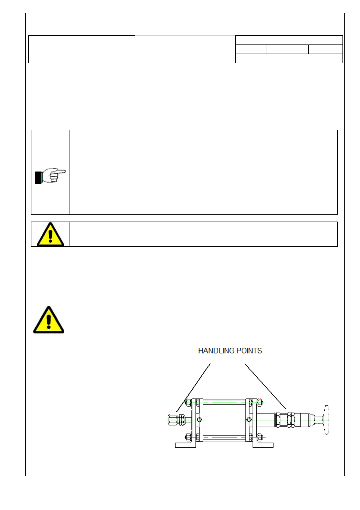
With such point of engagement, one
guarantees the balance of the machine
during the transport to the final destination.
Different points of engagement can cause
imbalance of the mass, with possible
dangers to people and with possible damage
to the machine
The machine has been projected and
constructed so that its stability - prescribed
AUTOMATOR INTERNATIONAL SRL –Via Meucci n.8–20094 Corsico (Mi) Italia
Tel 02 48601445 Fax 02 48601503 e-mail info@automator.com www.automator.com
Tel 02 48601445 Fax 02 48601503 e-mail info@automator. Com www.automator.com
Tel 02 48601445 Fax 02 48601503 e-mail info@automator. Com www.automator.com
Document
INSTRUCTION FOR USE
Code: MAN MBVPREV3
Ediz.n: 4
Del: 03/2012
Pag. 15/26
Edited by: U.T. VB
1.1.1.1.1.1 .
Appr. by: RB.
Machine:
VP UNITS
in point 1.3.1 of the law - is guaranteed during the transport, assembly and disassembling , in the course of
occasion breakdowns and tests, when all these operations are carried out in compliance with the manual .
In the observance of the Regulation EN 292-2, the unit does not present alive edges, acute angles, surfaces rough
which could be cause of lesions to people; same step of leave in overhang or edges out of sheet which could
cause contusions or wounds
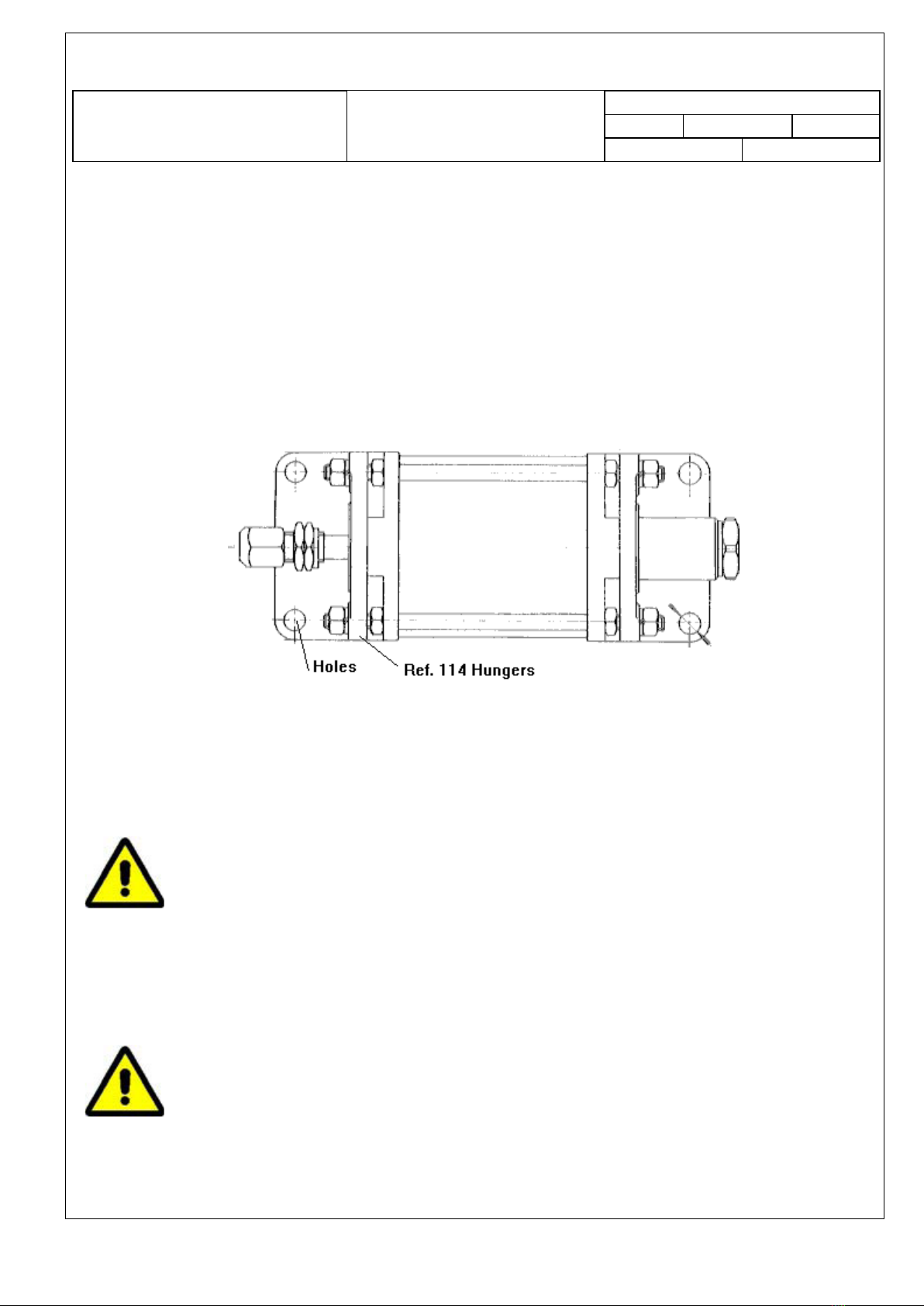
To install the unit , secure it with four bolts trough the hungers (Ref.114) to a rigid surface.
Fasten the bolts, with the inserts
The unit has to be firmly fixed to the support
The unit must not be subject to vibrations or movements.
The hungers can be removed if unnecessary
The unit must turn out fixed strongly to the support, that does not have to be subject to vibrations or movements
A wrong fixation of the machine to the table can provoke the fall or the unexpected
movement of the machine itself, causing damages to persons an/or things.
3.3 ADJUSTMENTS
Installation operations must be carried out by skilled, trained people, in total security
In case it is necessary to make the adjustment operations, switch off the machine

AUTOMATOR INTERNATIONAL SRL –Via Meucci n.8–20094 Corsico (Mi) Italia
Tel 02 48601445 Fax 02 48601503 e-mail info@automator.com www.automator.com
Tel 02 48601445 Fax 02 48601503 e-mail info@automator. Com www.automator.com
Tel 02 48601445 Fax 02 48601503 e-mail info@automator. Com www.automator.com
Document
INSTRUCTION FOR USE
Code: MAN MBVPREV3
Ediz.n: 4
Del: 03/2012
Pag. 16/26
Edited by: U.T. VB
1.1.1.1.1.1 .
Appr. by: RB.
Machine:
VP UNITS
➢Before putting in function the machine and at any doubt, the operator must read attentively the
instructions, making known its content to the interested people
➢In the search of a damage or a problem inherent the unit, adopt all the precautions necessary to
prevent any damage to people or things. Remove pneumatic tension, before acting
It is forbidden to use the machine for operations that are not contemplated in this manual, that is MARKING .
Automator International is not responsible for damage, risks or dangers to people, machine and to the
ambient for other applications than marking
3.3.1 HEIGHT ADJUSTMENT
The adjustment of the head height is defined by the
operator while mounting the VP unit on line, in relation
to the object to be marked.
The light between the surface to be marked and the
marking head MUST be less than 2mm, in order not to
put hands, fingers or other under the marking unit -
UNI EN 349
To adjust the height of the body in relation to the
dimensions of the piece to be marked, raise the body
on the support You fix the unit ; or, vice versa, lower it
down.
The two hungers (Ref. 114) have four holes to secure
the unit to the support. If unnecessary, the hungers
(Ref. 114) can be removed, unscrewing the four + four
bolts.
Fix tightly the unit on the support. If not,
it can fall or move during the
operations, slipping towards the bottom
The support holding the unit must non
be subject to vibration

AUTOMATOR INTERNATIONAL SRL –Via Meucci n.8–20094 Corsico (Mi) Italia
Tel 02 48601445 Fax 02 48601503 e-mail info@automator.com www.automator.com
Tel 02 48601445 Fax 02 48601503 e-mail info@automator. Com www.automator.com
Tel 02 48601445 Fax 02 48601503 e-mail info@automator. Com www.automator.com
Document
INSTRUCTION FOR USE
Code: MAN MBVPREV3
Ediz.n: 4
Del: 03/2012
Pag. 17/26
Edited by: U.T. VB
1.1.1.1.1.1 .
Appr. by: RB.
Machine:
VP UNITS
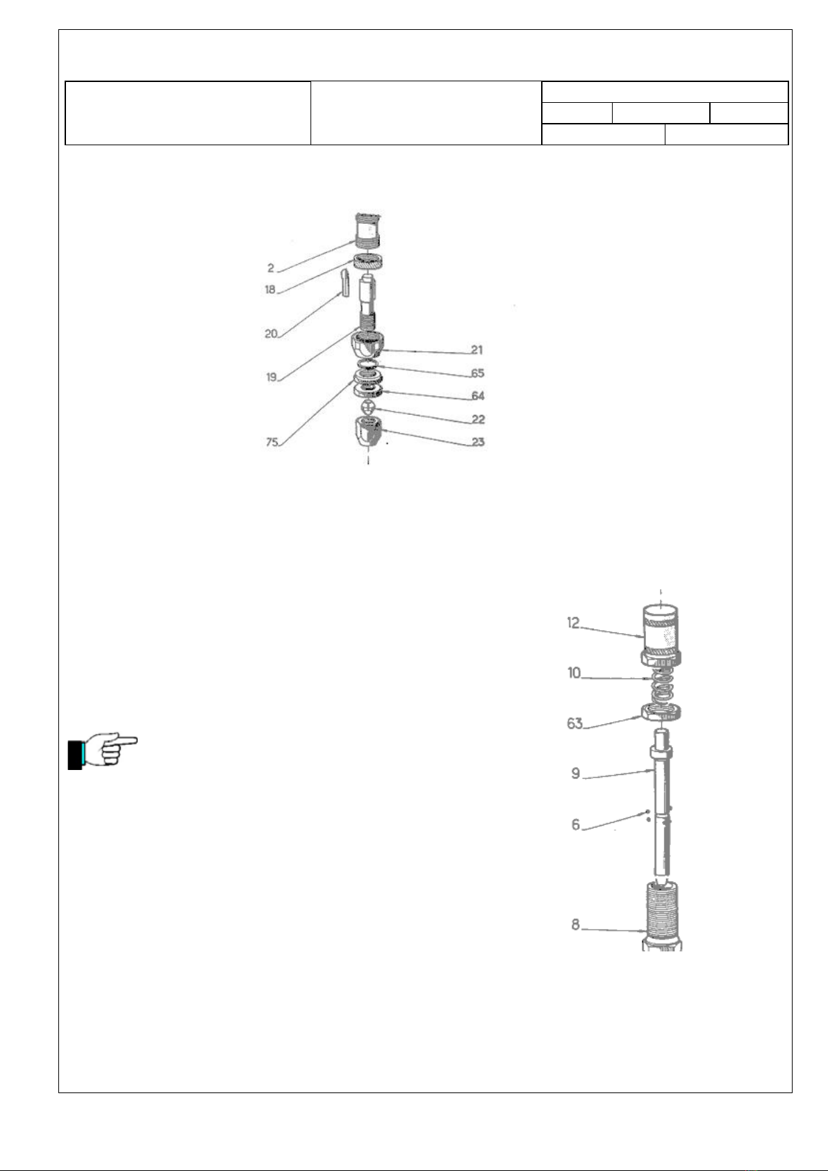
3.3.2 TYPEHOLDER INSERTION
To insert the type-holder or any other marking head,
loose the collet nut (Ref.23) e insert the shank with
the adequate diameter trough the above-mentioned
nut, which closes the collet (Ref. 22) e the ram anvil
(Ref.19). Once positioned the type-holder, tighten up
firmly the collet nut (Ref.23) to keep the marking
head in the desired alignment. The distance
between the shank and the collet nut must be about
1 o 2 mm.
Do not use hammers or other similar objects to
insert or secure the type-holder; in this case,
damages to the ram anvil or to the nut may occur
Note : Use only original shanks to avoid damages to
the ram anvil (ref. 19) or collet nut (Ref. 23)
If You do not use original Automator shank, when
screwing the collet nut, you can break the collet
The shank should move easily through the collet,
but there should be no play. The sizes of the shanks
for the different unit models are as follows :
MB19VPN –8mm
MB21VP –10mm
MB35VP –16mm
.
3.3.3 RAM ANVIL ADJUSTMENT
Do not block the ram anvil (Ref. 19) exaggerating in the locking of the key retaining nut (measure 6)
The unit will not operate unless the ram anvil (Ref. 19) moves freely and smoothly. In the axial sense,
it is suggested a tolerance from 3 to 5/10.
Please note that the impact force comes from the centre of the tool holder (Ref.19) and type holders or
any tooling should not make contact with the collet nut (Ref.23) when in operation.
AUTOMATOR INTERNATIONAL SRL –Via Meucci n.8–20094 Corsico (Mi) Italia
Tel 02 48601445 Fax 02 48601503 e-mail info@automator.com www.automator.com
Tel 02 48601445 Fax 02 48601503 e-mail info@automator. Com www.automator.com
Tel 02 48601445 Fax 02 48601503 e-mail info@automator. Com www.automator.com
Document
INSTRUCTION FOR USE
Code: MAN MBVPREV3
Ediz.n: 4
Del: 03/2012
Pag. 18/26
Edited by: U.T. VB
1.1.1.1.1.1 .
Appr. by: RB.
Machine:
VP UNITS
3.3.4 MARKING FORCE ADJUSTMENT
To regulate the marking force, turn the impact adjusting nut (Ref. 12)
clockwise to increase the force; counter-clockwise to decrease it. .
The unit is delivered with some impact springs of different thickness . To
replace the impact spring inside the unit with a different one, remove the
impact adjusting nut (Ref. 12) and the impact spring (Ref.10). Then place
the alternative spring inside the upper sleeve (Ref.8) and replace and tighten
the impact adjustment nut (Ref. 12).
Do not use the impact spring completely loaded, but use the
impact spring with a bigger thickness at a lower charge

AUTOMATOR INTERNATIONAL SRL –Via Meucci n.8–20094 Corsico (Mi) Italia
Tel 02 48601445 Fax 02 48601503 e-mail info@automator.com www.automator.com
Tel 02 48601445 Fax 02 48601503 e-mail info@automator. Com www.automator.com
Tel 02 48601445 Fax 02 48601503 e-mail info@automator. Com www.automator.com
Document
INSTRUCTION FOR USE
Code: MAN MBVPREV3
Ediz.n: 4
Del: 03/2012
Pag. 19/26
Edited by: U.T. VB
1.1.1.1.1.1 .
Appr. by: RB.
Machine:
VP UNITS
4 MARKING
Before marking, verify that :
➢The unit has been strongly and correctly fixed to a support
➢That the collect nut has been strongly screwed
➢The object to be marked has been positioned on an appropriate support
➢That the pneumatic connections fit the machine requirements
➢That the marking head (numbering head or type-holder) has been correctly mounted
The buyer declares that in case the pneumatic marking machine <…….> is used without
security, he has to complete it with adequate protections according to the CE following laws
89/395 and in particular CEE 89/392 CEE 91/368 art. 1 CEE93/44 art. 1 CEE 93/68 art. 6
The integrator must be prepared to complete the apparatus/unit with fit system of personal safety. That is,
it will be the manufacturer of such system to adjust the line itself to the normative CEE.
The Automator International Srl does prohibition of putting the pneumatic unit in service, if it has not been
completed with adequate safety system from the user.
Once performed successfully the adjustments (see Section 3.4. ), follow the steps for the first marking adjustment:
1. Position the part to be marked on the support
The support has to keep the marking head perpendicular to the piece to be marked
Automator assumes no responsibility for the use of a marking head that is not original delivery
Automator
2. Give the Start command
3. When the marking head touches the surface to be marked, the meachanism loads and marks
B

AUTOMATOR INTERNATIONAL SRL –Via Meucci n.8–20094 Corsico (Mi) Italia
Tel 02 48601445 Fax 02 48601503 e-mail info@automator.com www.automator.com
Tel 02 48601445 Fax 02 48601503 e-mail info@automator. Com www.automator.com
Tel 02 48601445 Fax 02 48601503 e-mail info@automator. Com www.automator.com
Document
INSTRUCTION FOR USE
Code: MAN MBVPREV3
Ediz.n: 4
Del: 03/2012
Pag. 20/26
Edited by: U.T. VB
1.1.1.1.1.1 .
Appr. by: RB.
Machine:
VP UNITS
5 MAINTENANCE
Ordinary maintenance operations must be carried out by experts and qualified personnel
The maintenance operations must be carried our when the machine has been disconnected
A regular maintenance, according to the details under described, is a guarantee either of the perfect operation
of the marking system in its mechanical and pneumatic parts or of the perfect operation of the safety system,
adopted to protect the Operator
Follow the instructions by using a thin layer of Vaseline or, alternatively, fluid-filled oil
Each 7 days, consist with the use of the machine:
•Lubricate the pignon (Rif. 26) of the lever (Rif. 35)
•lubricate the mechanism through the (Rif. 12)
•lubricate the rack
•lubricate the lever grease
Dense oils can cause excessive resistance of the parts in movement
We suggest to use filter to prevent damages to the impact mechanism, damages caused by impurity or water inside
the company pneumatic system.
Inside the appropriate filter bulb, put come industrial oil for lubrication
This manual suits for next models
3
Table of contents


