AutoMeter Digital Pro Shift User manual

INSTALLATION INSTRUCTIONS
Digital Pro Shift Gauge
2650-1942-77
QUESTIONS:
If after completely reading these instructions you have questions regarding the operation or installation of your instrument(s),
please contact AutoMeter Technical Service at 866-248-6357.
You may also email us at service@autometer.com.
Additional information can also be found at http://www.autometer.com/tech_faq.aspx
INTRODUCTION
Thank you for your purchase of the Digital Pro Shift from AutoMeter Products, Inc.
The following basic features are included on this product:
•Singlepreciseuser-programmablesetpoint •DigitalRPMdisplay •RPMdisplayblanking
•Quick-reacting,intensely-brightLEDshiftlight •Userselectabledimmingfunction
•Multipleshiftpointsettings •Colorchangeprogressiveshiftlightcapability
•Userselectableshiftlightcoloration •FullengineRPMplaybackcapabilitywith80secs.ofrecordtime.
PleasereadandfollowtheinstructionsbelowregardingtheinstallationandoperationofyourDPStoreceivemaximumbenetandaccuracyfromthisproduct.
Failure to follow the information below will void the product warranty and may result in damage to your vehicle, this product, and/or personal injury.
NOTE: This product features INTENSELY-BRIGHTLEDS!Thisfeatureisintendedformaximumdrivervisibilityduringdaytimeoperationandhighglare
situations.Usageofthisproductatfullbrightnessduringnighttimeorextremelydarksettingsmayadverselyaectdriver’svision.AutoMeterstrongly
recommends that you familiarize yourself with the dimming function of this product and that you do not operate the product at full brightness during
dim or dark lighting conditions.
INSTALLATION
1. Disconnect the negative (-) battery cable.
2.Gaugecanbemountedina21/16"dia.holewiththebracketsupplied.GaugecanalsobemountedinanAutoMeterMountingCup,Panel,
orAutoMeterGaugeWorksPod.
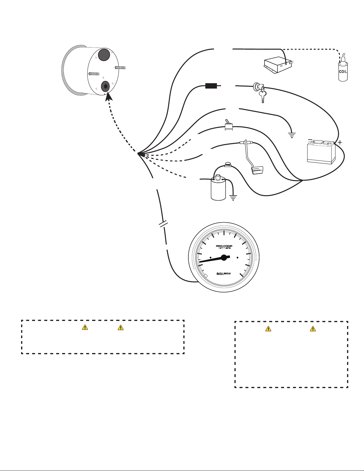
3.Wiregaugeasindicated.Seeschematiconfollowingpageformoreinfo:
Red Wire: Connecttoafusedandswitched12Vpositivesourcethatisturnedonandowiththeignitionswitch.
Black Wire: Connecttoagoodengine,chassis,orbatteryground.
Green Wire: Connecttothenegativeterminalofastandardignitioncoil,ortothe“TachOutput”terminalontheElectronicIgnitionModule.(Seediagram)
Blue Wire: (Optional)ConnecttopositiveterminalofTrans-BrakeorLineLockSolenoid.Alternatively,connecttotheBrakeLightSwitch,ClutchSwitch,
oradedicatedRemoteStartSwitch(normallyopen,momentaryclosed).
Violet Wire (Active only during playback): Connectthiswiretotheinput(greenwire)ofastandardAutoMetertachometer.
QUICK SET OPTIONS:
Day/Night Dimming control: This product is extremely bright at the maximum setting for best visibility for drivers during high glare situations. AutoMeter
does not recommend operating this product at full brightness during extremely dark or night time driving conditions. To adjust this product from the daytime or
“High”brightnesssettingtothenighttimeor“Low”brightnesssettingdothefollowing:
•PressandholdtheMENU (+) button for 2 seconds. The shift light will display the new brightness level and the display will indicate
whatmodeyouarechangingintowith“Hi”or“Lo”.
Launch RPM Quick Set –IfyouneedtochangeyourLaunchLightSettingquickly,dosowhenthevehicleengineisrunningandtheDigitalProShiftisin“Tach
Mode”byraisingtheengineRPMuntilyouhavereachedthedesiredsetpoint.PresstheENTERbuttontoconrmyournewLaunchLightSetting.Youshould
seetheDecimalindicatorashquicklytoconrm.
Remove RPM Display –Sometimesfewerdistractionsarebetterforadriver.Ifyouwanttobeabletofocusonjusttheshiftlightwhenyou’remakingaper-
formancerunanddon’twanttobedistractedbythedigitalRPMdisplay,youcandisablethedisplayfunction.Toturnon/othedisplayfunction,from“Tach
Mode,”pressandholdtheENTERbuttonfor2seconds.Thedisplaywillindicate“on”or“o”toindicatewhichmodeyouwillbechangingto.
NOTE:Thisfunctiontakesaectinallmodes.TheShift-LiteLEDSandthe“Preset/Record”indicatorLEDwillbetheonlyactiveelementsonthedisplay.
12V BATTERY
(-)
(-)
(+)
(+)
A
U
T
O
M
E
T
E
R
P
R
O
D
U
C
T
S
I
N
C
.
©
2
0
0
5
S
Y
C
A
M
O
R
E
I
L
U
S
A
4
4
9
7
ULTRA-LITE
RPM
THOUSANDS
10
1
0
2
456
7
8
9
3
OR
OR
OR
WIRING
Green
Fuse
Red
See“Warning”below
Tach output on
ElectronicIgnition
Ignition
Switch
12VBattery
Good
Engine
Ground
Tach
(SeeCautionBelow)
RemoteStartor
Manual Arm Switch
Caution
As a safety precaution, the +12V terminal of this product should be
fused before connecting to the 12V ignition switch. We recommend
using a 3 AMP automotive type fuse.
WARNING
Warranty will be void if connected to coil
when using an aftermarket ignition box such
as, but not limited to products from the fol-
lowingmanufacturers:MSD,Crane,Jacobs,
Mallory, Holley, Etc..Priorto installationof
your tachometer, check with the ignition box
manufacturer for recommended tachometer
signal location.
Violet
(Optional)
Brake or
Clutch
Switch
Trans Brake
or
Linelock
Solenoid
Black
Green
Blue
Blue
Blue
Good
Engine
Ground

C.) PLAYBACK MODE Press and release the MODE (+) .Thedisplaywillindicate“PLaY.”PressENTER to
conrmyourchoiceandbegin“playingback”therunstoredinthememoryonthedisplayat1⁄3real time.
To“Rewind”thecurrentrunbeingplayedback,pressandholdtheEXIT (–) button. The display will play the run backward from
itscurrentpositioninrealtime,foraslongasRewind/Pauseispressed.OnceRewind/Pauseisreleased,playbackwillbe“Paused”.
To resume playback at 1⁄3real time, press and release the MODE (+) button. Pressing and holding the MODE (+) will play the run forward in real time.
WhentheMODE (+) is released, playback will resume at 1⁄3realtime.DuringPlayback,theTachOutputonthevioletwirewillbeactive.
D.) SHIFT POINT SET –Once“SptS”isshownonyourdisplay,pressENTERtoconrmthatyouwouldliketosetyourshiftpointorpoints.“SP1”willnowbe
displayed. To set your shift point, press ENTERtoconrmtheshiftpointyouwouldliketoset.Thedisplaywillnowshowyouthecurrentshiftpointsetting.
UsetheMODE (+) and EXIT (–) buttons to raise and lower this number. A single press
resultsina10RPMincrementchange.PushandholdeachbuttontoscrollmorequicklythroughtheRPMscale.Onceyouhavedialedinthedesiredset
point, press ENTERtoconrmyourchoice.NavigatetoadditionalshiftpointsettingsbypressingtheMODE (+) button. Set these additional points using
the process described above.
NOTE: Itisrecommendedthatyousettheshiftpointto3000RPM(orasimilarlymidtolowpointinyourengine’srevrange)toconrmproperinstallation.
WiththeDPSonandinTachmode,bringtherevsofthevehicleto3000RPMandverifythatthelightactivatesasspecied.Oncethistestis
completeddialupyourshiftpointtoyourdesired,orenginebuilderspeciedRPMsetting.
NOTE: Ifasetpointhasbeenchanged,allhigherShift-Litesetpointswillalsobechangedtothesamevalue.AlllowerShift-Litesetpointswillbeleft
unchanged.Forexample,ifShift-Litesetpoint#2ischangedto6,000RPM,setpoints#3and#4willalsobechangedto6,000RPM.
Setpoint#1willnotbechanged.Setpoint#5istheLaunchRPMandwillnotchangewhensetpoints#1-4arechanged.
E.) *LAUNCH LITE SET – TheDigitalProShifthasaLaunchLitesettingfordragracingapplicationsandother
formsofmotorsportthatcanbenetfromapreciselaunchRPMfromadeadstop.WhentheLaunchLiteisactive,theshiftlightwillperformasfollows:
•WhentheRPMisbelowtheLaunchRPMSetPoint:theshiftlightwillbeo.
•WhentheRPMisattheLaunchRPMsetpoint+/-100RPM:theshiftlightwillbeon.
•WhentheRPMisabovetheLaunchRPMsetpoint:theshiftlightwillash.
Press the MODE (+)buttonuntil“SptS”isdisplayed,pressENTERtoconrmthischoiceandthenpressMODE (+)until“LnCH”isdisplayed.
Press ENTERtoconrmyourchoicetosetyourlaunchlightRPM.UsetheMODE (+) and EXIT (–)buttonstoscrollupanddownuntilyourdesiredRPM
set point is displayed. Press ENTERtoconrmyourLaunchLitesetpoint.
*LAUNCH RPM QUICK SET –IfyouneedtochangeyourLaunchLightSettingquickly,youcandosowhenthevehicleengineisrunningandtheDigital
ProShiftisonbyraisingtheengineRPMin“TachMode”untilyouhavereachedthedesiredsetpoint.PresstheENTERbuttontoconrmyournew
LaunchLightSetting.YoushouldseetheDecimalindicatorashquicklytoconrmyournewsetting.
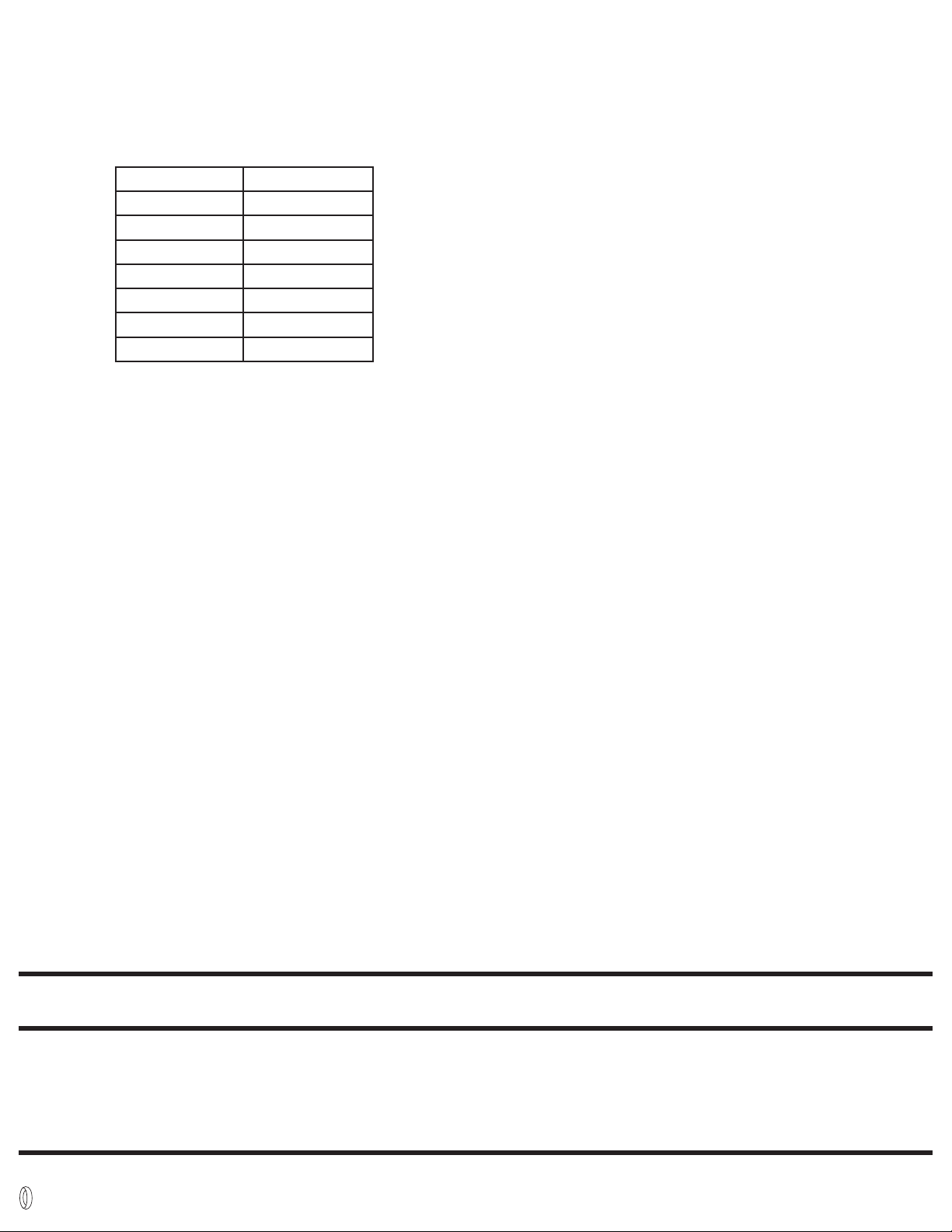
F.) PULSE PER REVOLUTION SET (CYL. CALIBRATION) –UsethisfeaturetocalibrateyourDigitalProShifttoyourengineandignitiontype.To
enterPulsePerRevolutionSet,presstheMODE (+)buttonuntil“PPr”isdisplayed,thenpressENTERtoconrmyourselection.Youmaynowusethe
“+” and “–” buttons to cycle up and down through the pulse settings available on this product. Pulse per revolution settings refer to the number of pulses
or“plugrings”providedbytheignitiontothedeviceperenginecrankrevolution.Forexampleasinglecoilignitionona4-cylinderenginewilltypicallyre
twocylinderspercrankrevolution.Ifyourignitionmatchedthistype,youwouldneedtosetyourPPrvalueto“2”(†See below). Below is a list of common
ignitionpulsesettings.IfyouneedfurtherassistancecalibratingthisunitforyourapplicationpleasevisitourTechTipsandFAQsectiononourwebsite
(http://www.autometer.com/tech_faq.aspx) or contact AutoMeter tech support personnel via the information included with the warranty information
shown later on this sheet.
†The available ignition pulse settings are .5, 1, 1.5, 2, 2.5, 3, 4, 5 & 6.
B.) RECORD MODE –TheDPSmustbein“Preset”modebeforetheRecordmodecanbestarted.
Thisisaccomplishedbyapplying+12vtotheBluewire.Thiscanbedonewitharemotestartswitch,
transbrakeorlinelocksolenoid,brakeswitchorclutchswitch(refertotheWiringdiagram).Therightmost
decimalpointshouldnowbeblinkingindicatingthatyouhaveentered“Preset”mode.
WhileinPresetmode,theLaunchLitefunctionwillbecomeactive.Inthismode,theShift-Litewill
perform as follows:
WhentheRPMisbelowtheLaunchRPMSetPoint:theShift-Litewillbeo.
WhentheRPMisattheLaunchRPMsetpoint+/-100RPM:theShift-Litewillbeon.
WhentheRPMisabovetheLaunchRPMsetpoint:theShift-Litewillash.Oncetheunitenters
Recordmode,theLaunchLitefunctionwillnolongerbeactive.
TostartarecordingfromPresetmode,removethe+12voltstothebluewire(refertotheWiringdiagram).
The right-most decimal indicator will change to a constant lit state indicating recording is in progress.
NOTE:WheneveraRecordModeisstarted,anypreviouslyrecordedruninformationwillbeover-written.
Thedevicewillcontinuetorecordforthespeciedmaximumtimeperiod(80seconds),oruntilEXIT(–)ispressed,or+12volts
isre-appliedtotheBluewire,whichevercomesrst.Thedecimalindicatorwillturnoattheendoftherecording.
NOTE:DuringtheRecordMode:
• 450RPM“ShortShiftProtection”isprovided.Thiswilladvancetheshift-litesettingfromoneshiftpointtothenextwhenthe
enginedrops450RPMormore.Forexample,ifshiftpoint#1issetat6,000RPMandyoushortshiftat5,000RPMthetach
willautomaticallyadvancetoshiftpoint#2eventhoughyouneverreached6,000RPMandthelightneverturnedon.
• Duringarun,afterthelastshiftpoint,theShift-LitealwayscomeonatRPMSettingofthelastshiftpoint.
Iftheunitispowereddownduringarecording,thetachwillreturnto“Tach”modewhenpowerisappliedandtheengineis
running. The recording will be available for playback up to the point that power was removed.
SETUP and OPERATION MODES
A.) MENU MODE – To Select Menu Mode, press the MODE (+) button. To exit setup mode and return to
RealTimedisplay,pressEXIT (–).
ENGINE Most 2 cyl. Most 4 cyl. Most 6 cyl. Most 8 cyl.
PPR 0.5 1 1.5 2.0 2.5 3 4 5 6
G.) Launch Lite Enable - The Launch Lite feature can be Enabled or Disabled.
PressandreleasetheMODE(+)buttonuntil“LEn”isshownonyourdisplay,pressENTERtoconrmthatyouwouldliketo
Enable or Disable this feature. The current setting will be displayed, either “LEoF” for Disabled or “Leon” for Enabled. Press the MODE (+) button to
Enable, or the ENTER button to Disable. Press the EXIT (–) button to save the setting.
H.) *SHIFT LIGHT COLOR SET –ToadjustthecolorofthelightonyourLevel2or3product,presstheMODE (+) buttonuntil“CoLr”isdisplayed,thenpress
ENTERtoconrmyourchoice.
•Ifthisisyourrsttimeselectingthecolor,yourfactoryprogrammedpresetisRED.Whenyouenter“CoLr”fromthemenu,thedisplayshould
indicate“1”andtheshiftliteshouldilluminateRED.UsetheMODE (+) and EXIT (–)buttonstocycleupanddownthecolorchoices.Usethe
chart below for your reference.
• PressENTERtoconrmyourcolorchoiceandreturntoMenuMode.
• NOTE:Ifyellowischosenasshiftlightcolor,progressiveearlywarninglightcolorchangestoMagenta,seeProgressiveShiftLightsetformoreinfo.
I.) SHIFT LIGHT BRIGHTNESS SET – To adjust the high and low brightness settings of your Digital Pro Shift, press the MODE (+)until“LLV”(LightLeVel)is
displayed and press ENTERtoconrmyourchoice.
• “Lo”isdisplayed.Factoryprogrammedpresetisthelowestsetting,“1.”Toadjust,usethe MODE (+) and EXIT (–) buttons. Max brightness setting
fortheLowlevelfromthefactoryis“11.”
NOTE: Lowbrightnesssettingcannotbesethigherthan4lightlevelsbelowtheHighsetting(i.e.iftheHighbrightnesssettingischangedto“11”the
newdefaultLowlevelsettingwillbe“7”andcannotbeincreaseduntiltheHighsettingisincreased).
• PressENTERtoconrmyourLow(dim)levelsettingandproceedtoyourHigh(bright)levelsetting.
•“Hi”isdisplayed.Factoryprogrammedpresetisthebrightestsetting,“15.”Toadjust,usetheMODE (+) and EXIT (–) buttons.Lowestbrightness
settingfortheHighsettingfromthefactoryis“5”.
NOTE: Highbrightnesssettingcannotbesetlowerthan4lightlevelsabovetheLowsetting(i.e.iftheLowsettingis“7”,theHighsettingcannotbe
setlowerthan“11”withoutrstloweringtheLowsetting.).
• PressENTERtoconrmyourHigh(bright)levelsettingandreturntomenuselectoption.
J.) PROGRESSIVE SHIFT LIGHT SET – The progressive shift light feature of this product enables a color change and blink feature to alert the driver of the
approachingshiftpointaswellasapotentialover-revsituation.Toadjustthissettingsofthisfeatureorturnitonoro,presstheMODE (+) button until
“PSL”isdisplayed,thenpressENTERtoconrmyourchoice.
• “PSL1”shouldnowbedisplayed.Thisistheearlywarningpointandisindicatedbyasolidyellowlight.Toadjustthispoint,pressENTER.Usethe
MODE (+) and EXIT (–) buttons to adjust the percentage of the current shift point set that you would like the progressive early warning color to
activate. The factory programmed preset for this point is 60%. This entry may be set as low as 10% of the current shift point, or as high as 1 below the
PSL2setting.SettingthisfeaturetoonebelowPSL2disablesthisfeature.Onceyouhaveselectedthedesiredvalue,pressENTERtoconrm.
•“PSL2”willbedisplayedifyoupresstheMENUbuttononceafter“PSL1”isdisplayed.Thisistheshiftpointapproachingwarningindicatedbya
blinking yellow light. To adjust this point, press ENTER.Usethe MODE (+) and EXIT (–) buttons to adjust the percentage of the current shift point set
thatyouwouldliketheprogressiveearlywarningcolortoactivate.Thefactoryprogrammedpresetforthispointis80%.Thisentrymaybesetas
lowas1abovePSL1,orashighas100%.Settingthisfeatureto100%disablestheblinkingyellowlightfeatureoftheprogressiveshiftlightfunction.
Onceyouhaveselectedthedesiredvalue,pressENTERtoconrm.
•“PSL3”willbedisplayedifyoupresstheMODE (+)buttontwiceafter“PSL1”isdisplayed.Thisistheover-revwarningandisindicatedbyablinking
red light. To adjust this point, press ENTER.UsetheMODE (+) and EXIT (–) buttons to adjust the percentage of the current shift point set that you
would like the progressive over-rev warning color to activate. The factory programmed preset for this point is 110%. This entry may be set as low as
101%orashighas150%ofthecurrentshiftpointsetting.Onceyouhaveselectedthedesiredvalue,pressENTERtoconrm.
• “on”/“oFF”PresstheMODE (+) buttonthreetimesafterthedisplayshows“PSL1”inordertobeabletoturnonorotheprogressiveshiftlightfunction.
Thefactoryprogrammedpresetforthisfunctioniso.UsetheENTERbuttontotogglethissettingonoro,theMODE (+)buttontoconrmorthe
EXITbuttontocancel.
•*NOTE: If you have selected yellow as your chosen shift light color, your early warning progressive light color will change to Magenta.
It will default to yellow for all other color options. The over rev feature remains blinking red even if red is selected as the chosen
shift light color.
K.) PEAK Recall –TheDPSfeaturesa“peak”recallormemorytorecallthehighestRPMreachedduringaparticularrun.ScrollthroughtheMenu
Mode [MODE (+)]untilthedisplayreads“PEAC”thenpressENTER.ThiswilldisplaythehighestRPMachieved.ToclearthepeakpressMODE (+).
Display Indicater Shift Light Color
0White
1Red
2 Yellow
3Green
4 Teal
5 Blue
6 Magenta
12 MONTH LIMITED WARRANTY
AutoMeter Products, Inc. warrants to the consumer that all AutoMeter High Performance products purchased from an Authorized AutoMeter Reseller will be free from defects in material and workmanship for a
period of twelve (12) months from date of the original purchase. Products that fail within this 12 month warranty period will be repaired or replaced at AutoMeter’s option, when determined by AutoMeter that the
product failed due to defects in material or workmanship. This warranty is limited to the repair or replacement of parts in the AutoMeter High Performance product and the necessary labor done by AutoMeter to
effect the repair or replacement of the AutoMeter High Performance product. In no event shall AutoMeter’s cost to repair or replace an AutoMeter High Performance Product under this warranty exceed the original
purchase price of the AutoMeter High Performance Product. Nor shall AutoMeter Products, Inc. be responsible for special, incidental or consequential damages or costs incurred due to the failure of an AutoMeter
High Performance Product. This warranty applies only to the original purchaser of the AutoMeter High Performance Product and is non-transferable. This warranty also applies only to AutoMeter High Performance
Products purchased from an Authorized AutoMeter Reseller. All implied warranties shall be limited in duration to the said 12 month warranty period. Breaking the instrument seal, improper use or installation,
accident, water damage, abuse, unauthorized repairs or alterations voids this warranty. AutoMeter disclaims any liability for consequential damages due to the breach of any written or implied warranty on all
products manufactured by AutoMeter Products, Inc. For a comprehensive listing of Un-Authorized AutoMeter Resellers please visit www.autometer.com/autometerlocator/index/unauthorized.
FORSERVICESENDTO:AutoMeter PRODUCTS, INC.413W.ElmSt.,Sycamore,IL60178(866)248-6357
ForEmail:Service@autometer.com
2650-1942-77 10/6/17
The “Super Bezel” is a registered trademark of AutoMeter Products, Inc.
SERVICE
ForservicesendyourproducttoAutoMeterinawellpackedshippingcarton.Pleaseincludeanoteexplainingwhattheproblemisalongwithyourphonenumber.Ifyouaresending
product back for warranty adjustment, you must include a copy (or original) of your sales receipt from the place of purchase.
© 2017 AutoMeter Products. Inc.
Table of contents
Other AutoMeter Automobile Accessories manuals


