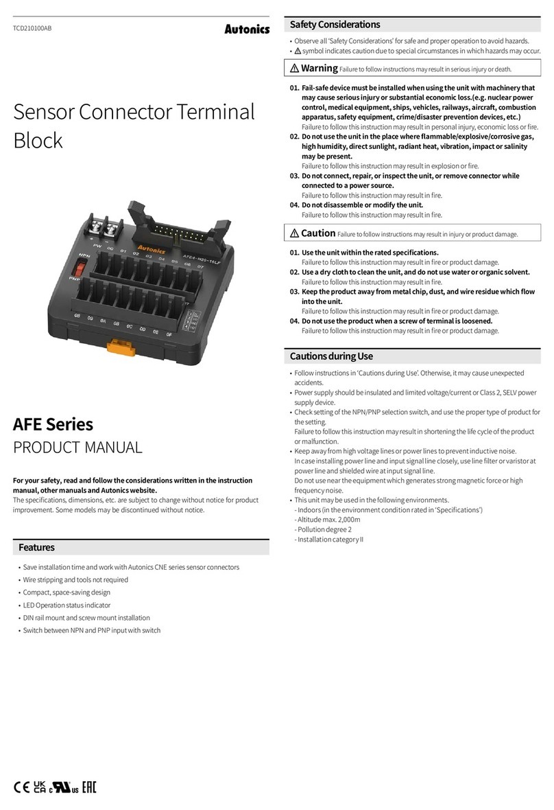
Autonics AiS-D Series User manual

-|Transparent Guide|-
TCD210117AA_MODI
2-Closed-loop
Stepper Motor Driver
AiS-D Series
PRODUCT MANUAL
For your safety, read and follow the considerations written in the instruction
manual, other manuals and Autonics website.
Features
•
•
•
•
Safety Considerations
•
•
01.
02.
03.
04.
05.
06. Do not disassemble or modify the unit.
07.
08.
09.
01. 2
02. 2
over.
03.
04. It is recommended to use STOPPER for the vertical load.
05.
06.
07.
this driver.
08.
09.
10.
11.
unit.
12.

-|Transparent Guide|-
AiS -D- -
A
B
-
•
•
•
•
•
•
•
•
•
•
•
•
•
•
• 2
•
•
•
•
•
Dimensions
•
144
3
134
144
Alarm
No. of
No. of
1 7
2Overspeed error
3 9
4Overload error 10
Overheat error 11
6 12
No. of
4
01 02 03 04 05 06
07 08
01. Power connector
02.
03.
04.
switch
05.
06.
07. Status indicator
08. Function selection DIP switch
Status Indicators
Indicator Color
applied
Red

-|Transparent Guide|-
Causes
Insulation resistance
Vibration
Shock 2
Ambient humi.
Run method
In-Position
Rotation direction
AB
frequency
Pulse width
Rise fall time
Resolution
Resolution
10000 PPR
Switch
•
Delay Delay
0
1 9
2 A
3 B
4 C
D
6 E
7 F
•
P I P I
0 1 1 3 2
1 2 1 9 4 2
2 3 1 A 2
3 4 1 B 1 3
41 C 2 3
6 1 D 3 3
6 1 2 E 4 3
7 2 2 F 3
Connectors
Power connector
Pin Function
1
2
1
2
Pin Function Pin Function
1
2 9A
3 10 B
4 11
PE 12 N·C
6Motor A 13 Motor B
7Motor A14 Motor B
Encoder
13 12 11 10 914
7 6 234
1
Pin Function Pin Function
1 11
2 12
3 13
4 14
Servo ON/OFF+
6Servo ON/OFF- 16 A
7 17
B
9 19
10 20
10 ··· 14··
··
··
···20 1114··
•
HANLIM
3M

-|Transparent Guide|-
Res.
PPR Resolution PPR Resolution
11000 1000
21600 1600
32000 10 2000 10
43200 16 3600
3600
6 6400 32
76400 32 7200 36
7200 36 10000
910000 16000
INP.
Value Value
00
1 9
2 A
3 B
4 C
D
6 E
7 F
Function selection DIP switch
No. Function ON OFF
1
2
3
stops
4
-
•
Rotation
Rotation
•
•
Connections
N·C
M
O
T
O
R
E
N
C
O
D
E
R
1
2
3
4
6
7
9
10
12
11
13
14
16
17
19
20
1
2
6
7
13
14
12
2
9
3
10
4
11
1
+
-
Motor
A
A
B
B
A
A
B
B
N·C
Servo ON/OFF+
Servo ON/OFF-
A
B

-|Transparent Guide|-
In-Position
•
•
•
•
•
•
•
•
•
•
•
Alarm Reset
•
•
•
•
• CC
• CCLCC
RL CC
• CCL
VCC RL
Pull-Down circuit
Driver
CC
RL
-
CC
RL
-
Driver
Driver
CC
RL
CB
E
-
-
Driver
CC
RLC
B
E
connection
Pull-Down circuit
Driver
-
Driver
-
Driver CB
E
-
-
Driver
C
B
E
•
1 12 23 3
• Alarm
No. of
1
2Overspeed error
3
error
4Overload error
Overheat error
6
error
7
error
9
error
10
11
12
•
No. of
4
• CCL
L CC F
L CC
• F
Driver
CC
RL
+
-
-
+
Driver
CC
RL
+
-
Driver
CC
RL
+
-
•
•
•
Driver
Brake
1 sec

-|Transparent Guide|-
•
•
•
•
Pin Cable color Dot line color-number
1
2 Red-1
3
4 Red-2
Servo ON/OFF+
6Servo ON/OFF- Red-3
7
Red-4
9
10
11
12 Red-1
13
14 Red-2
16 ARed-3
17
BRed-4
19
20
•
•
Table of contents
Other Autonics Network Hardware manuals
Popular Network Hardware manuals by other brands

D-Link
D-Link DNS-323 - Network Storage Enclosure NAS... Quick install guide

Sensys Networks
Sensys Networks VDS240 installation guide

AoFrio
AoFrio Network Pro ONE Product guide

FieldServer
FieldServer FS-8700-114 X30 Driver manual

Addi-Data
Addi-Data MSX-E Series Technical description

FieldServer
FieldServer Carrier DataLink FS-8700-82 Driver manual