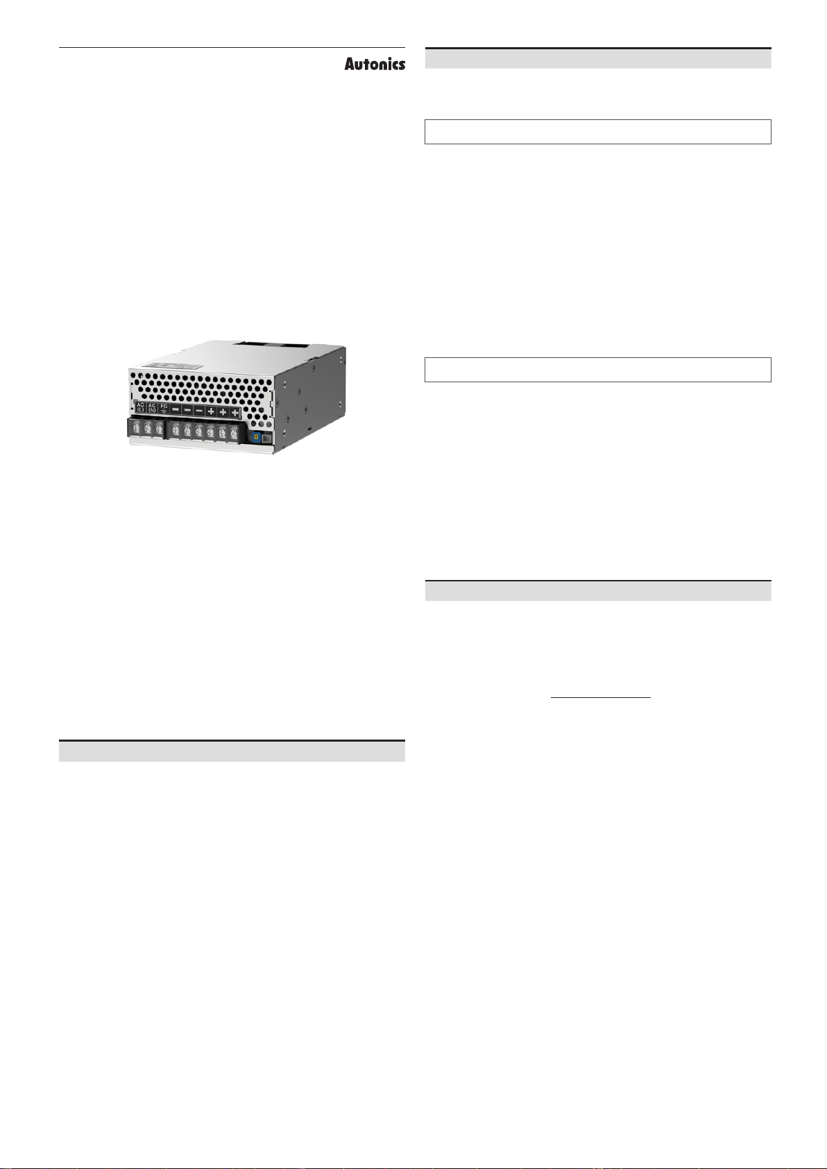
manuals.online logo
Brands
  1. Home
  2. •
  3. Brands
  4. •
  5. Autonics
  6. •
  7. Power Supply
  8. •
  9. Autonics SPA-400-24 Series User manual

Autonics SPA-400-24 Series User manual

-|Transparent Guide|-
TCD210173AB
Panel Mount SMPS
SPA-400-24 Series
PRODUCT MANUAL
For your safety, read and follow the considerations written in the instruction
manual, other manuals and Autonics website.
The speci󹃒cations, dimensions, etc. are subject to change without notice for product
improvement. Some models may be discontinued without notice.
ᜢ ᜹
Major Features
• Built-in over-current protection circuit, output short-circuit protection circuit, and
over-voltage protection circuit
• EN 60950 (Safety of information technology equipment) compliant
• EN 50178 (Electronic equipment for use in power installations) compliant
• EN 61000-6-2 (EMC: immunity for industrial environments) compliant
• EN 61000-6-4 (EMC: emission standard for industrial environments) compliant
• Output voltage: 24 VDCᜡ
• Output power: 400 W
Safety Considerations
• Observe all ‘Safety Considerations’ for safe and proper operation to avoid hazards.
• ᜸ symbol indicates caution due to special circumstances in which hazards may
occur.
 Failure to follow instructions may result in serious injury or death.
01. 
. nuclear power
control, medical equipment, ships, vehicles, railways, aircraft, combustion
apparatus, safety equipment, crime/disaster prevention devices, etc.)
Failure to follow this instruction may result in personal injury, economic loss or 󹃒re.
02. 󹃓

present.
Failure to follow this instruction may result in explosion or 󹃒re.
03. . terminal separately.
Failure to follow this instruction may result in 󹃒re or electric shock.
04. Do not connect, repair, or inspect the unit while connected to a power
source.
Failure to follow this instruction may result in 󹃒re or electric shock.
05. Check 'Connections
Failure to follow this instruction may result in 󹃒re.
06. Do not disassemble or modify the unit.
Failure to follow this instruction may result in 󹃒re or electric shock.
 Failure to follow instructions may result in injury or product damage.
01. . 2) cable or over and

Failure to follow this instruction may result in 󹃒re or malfunction due to contact
failure.
02. 󹃒
Failure to follow this instruction may result in shortening the life cycle of the
product, 󹃒re, or product damage.
03. 
Failure to follow this instruction may result in electric shock or 󹃒re.
04. 󹃓
Failure to follow this instruction may result in 󹃒re or product damage.
05. 

Failure to follow this instruction may result in burns.
06. Upon occurrence of an error, disconnect the power source.
Failure to follow this instruction may result in 󹃒re or product damage.

• Follow instructions in ‘Cautions during Use’.
Otherwise, it may cause unexpected accidents.
• Do not connect the output voltage neither in serial nor in parallel.
• Since there is no harmonic suppression or power factor correction circuit, install the
circuit separately if necessary.
• Since using the condenser input method, power factor is in the range of 0.4 to 0.6.
When using distribution board or transformer, check the capacity of the input voltage.
Input apparent power[VA] = Output active power[W]
Power factor×E󹃔ciency
• Even though a noise 󹃒lter is installed inside the product, the product can be a󹃑ected
by noise depending on the installation location or wiring.
• If the internal fuse is damaged, please contact our A/S center.
• To ensure the reliability of the product, install the product on the panel or metal
surface vertically to the ground.
• Install the unit in the well ventilated place.
-|Transparent Guide|-
• Do not use near the equipment which generates strong magnetic force or high
frequency noise.
• This unit may be used in the following environments.
- Indoors (in the environment condition rated in 'Speci󹃒cations')
- Altitude max. 2,000m
- Pollution degree 2
- Installation category II
Connections
• Wire: AWG 18 to 16, Torque: 0.7 to 0.9 N·m Mark Function
N, L Input power
FG F.G. frame ground
-GND, output power (-)
++24V, output power (+)

L -
-
-
-
-
-
+
+
+
+
+
+
Dimensions
• Unit: mm, refer to the Autonics website for the details of the product.
4-M4
(Bottom side)
4-M4
(Both side)
204.8
190.2
150
150
16
4.310.3
16
120
100
61
3812.5
15.6
30.5
2-9.5
10
9
5-9.5
6-M3.5
3-M3.5
Output indicator
()
Remote control
connector
Output
adjuster (V.ADJ)
󹃒
Model SPA-400-24
Output power 400.8 W
Input
condition
Voltage 01) 200 - 240 VACᜠ (permissible voltage: 190 - 264 VACᜠ)
Frequency 50 / 60 Hz
E󹃔ciency 02) (typical) ≥ 85% (10 min after power ON)
Current consumption 02)
(typical) ≤ 4.6 A
Leakage current 02) (typical) ≤ 1 mA
Inrush current protection 02)
(typical) 40 A
Output characteristics
Voltage 24 VDCᜡ
Current 16.7 A
Voltage adjustment range 03) ≤ ±5%
Input variation ≤ ±0.5%
Load variation ≤ ±1%
Temperature drift 360 mV
Ripple noise ≤ 290 mV
Start-up time 02) (typical) 1,800 to 2,300 ms
Hold time 02) (typical) ≥ 17 ms
Protection
Over-current protection 110 to 160% (recovers automatically after the cause for over current
is removed)
Over-voltage protection 03) 27 - 33 VDCᜡ
Temperature rising limit Yes
Remote control Yes (output voltage ON for shorting, output voltage OFF for open)
Product Components • Product • Instruction manual
󹃒 ᜢ ᜹
U ≈ 885 g (≈ 975 g)
Indicator Output indicator (green)
Insulation resistance Between all input terminals and F.G.: ≥ 100 MΩ (at 500VDCᜡ megger)
D Between all input and output terminals: 3,000 VACᜠ 50/60 Hz for 1 min
Between the charging part and the F.G.: 2,000 VACᜠ 50/60 Hz for 1 min
Vibration 0.75 mm amplitude at frequency of 10 to 55Hz in each X, Y, Z direction for
2 hours
EMS EN61000-6-2 compliant
EMI EN61000-6-4 compliant
Safety standards EN60950, EN50178
Ambient temperature -10 to 50 ℃, storage: -20 to 75 ℃ (no freezing or condensation)
Ambient humidity 20 to 90%RH, storage: 20 to 90%RH (no freezing or condensation)
Fan life cycle 70,000 hours (based on 40 ℃ of ambient temperature)
01) Since there is no separate input overvoltage protection for the voltage over the rated input voltage range,
supplying overvoltage may result in product damage.
02) It is for 220 VACᜠ, 100% load.
03) Use the output voltage adjusting volume within the voltage variable range. If the voltage exceeds the out-
put voltage range, overvoltage protection function is activated and the output is cut o󹃑.
󹮶
100
80
60
40
20
0
Ambient temperature (℃)
50
-10 010 20 30 40 50 60 70
Load ratio (%)

Input voltage ( VACᜠ)
100
80
60
40
20
0
190 200 210 220 230 240 270260250
Load ratio (%)
264
󹮶
When the over rated current is 󹃓owed, the over-current protection circuit is operated to
protect the product by reducing output voltage.
The protection circuit is released automatically when the load current is under the
rated current.
• It is for the rated input voltage 220 VACᜠ with 100% load.
Rated current
Output current (%)
Output voltage (V)
󹮶
To protect the connected load, the output is disconnected when the over-voltage is
detected.
When the output is disconnected, apply the power after waiting at least 3 minutes.
Operation range of over-voltage
protection function
(Over-voltage protection ±10%)
Output voltage range can not
be covered within standard
Output voltage 󹃓uctuation range
(Rated output voltage ±5%)
Rated output
voltage
Over-voltage
protection
Voltage
Time
0V
18, Bansong-ro 513Beon-gil, Haeundae-gu, Busan, Republic of Korea, 48002
󹮷󹮷󹮶󹮶󹮶󹮷
-|Transparent Guide|-

Over-current,
over-voltage
protection
circuit
Auxiliary
power
Output
+ -
Remote
ON / OFF
Input
200 - 240 VACᜠ
50/60 Hz
Recti󹃒er
circuit Recti󹃒er
circuit
Inrush current
limit circuit
Input/
Noize 󹃒lter AC1 (L)
AC1 (N)
F.G.
Control circuit

Other Autonics Power Supply manuals

Autonics ARIO-C-EI User manual

Autonics

Autonics ARIO-C-EI User manual

Autonics SPB Series User manual

Autonics

Autonics SPB Series User manual

Popular Power Supply manuals by other brands

Spellman EBM30N/TEG Installation and user guide

Spellman

Spellman EBM30N/TEG Installation and user guide

Matsusada EC Series instruction manual

Matsusada

Matsusada EC Series instruction manual

voss.pet Fenci M03 operating instructions

voss.pet

voss.pet Fenci M03 operating instructions

LEAB LPS Series user manual

LEAB

LEAB LPS Series user manual

EFOY ProEnergyCase 2020P-3 user manual

EFOY

EFOY ProEnergyCase 2020P-3 user manual

Poppstar 1008824 Instructions for use

Poppstar

Poppstar 1008824 Instructions for use

Elenco Electronics XP-15 Instruction & assembly manual

Elenco Electronics

Elenco Electronics XP-15 Instruction & assembly manual

Listen Technologies LBB 400D Specification sheet

Listen Technologies

Listen Technologies LBB 400D Specification sheet

Horizont farmer AN1000 Solar instruction manual

Horizont

Horizont farmer AN1000 Solar instruction manual

Rosslare PC-15R Installation instructions and operators manual

Rosslare

Rosslare PC-15R Installation instructions and operators manual

Keysight Technologies N6900 Series Operating and service guide

Keysight Technologies

Keysight Technologies N6900 Series Operating and service guide

Rockwell Automation 1606-XLS960 instruction manual

Rockwell Automation

Rockwell Automation 1606-XLS960 instruction manual

Pulsar MSC 1512 instructions

Pulsar

Pulsar MSC 1512 instructions

StarTech.com ATXPOWER250 manual

StarTech.com

StarTech.com ATXPOWER250 manual

Matsusada Precision R4GN Series Basic instruction manual

Matsusada Precision

Matsusada Precision R4GN Series Basic instruction manual

RTS PS8 Technical manual

RTS

RTS PS8 Technical manual

Workrite Ergonomics ACC-HPED-PWR-B Assembly/installation instructions

Workrite Ergonomics

Workrite Ergonomics ACC-HPED-PWR-B Assembly/installation instructions

Ametek XPD 120-4.5 Operation manual

Ametek

Ametek XPD 120-4.5 Operation manual

manuals.online logo
manuals.online logoBrands
  • About & Mission
  • Contact us
  • Privacy Policy
  • Terms and Conditions

Copyright 2025 Manuals.Online. All Rights Reserved.