mini-box M4-HV ATX User manual

M4-HV ATX
6-34V Intelligent ATX Power Supply
Installation Guide
Version 1.0e
P/N M4- V ATX-01
Before you start...
Please take a moment and read this manual before you install the M4- V ATX in your vehicle.
Often times, rushing into installing the unit can result in serious damage to your M4- V ATX
board, computer and probably your car's electrical system. Always double check the
olarity of your wires with a voltmeter.
Avoid using the cigarette plug as a power source, often times the contacts are not capable of
delivering high current to your PC.
Introduction
Thank you for purchasing the M4- V ATX power sequencer / vehicle ATX power supply. The
M4- V ATX was designed to work with a wide variety of main boards ranging from low power
to fully fledged Intel, AMD or VIA models (such as the VIA mini-ITX motherboards as well as
Pentium-M / Celeron / Core2Duo or full power Pentium systems).
M4-HV ATX Logic Diagram
1

M4-HV ATX Power In ut Connectors (bottom, right side)
Left Battery negative (GND)
Center Ignition (To start connect to Battery +)
Do not use in the standard PSU mode (mode P0)
Right Battery positive (+)
(A) ATX Power Output Connector 20/24 pin connector
(B) 12V-ATX power output connector 4 pin
(C) Configuration dip switch
(J5) For internal use only (do not use)
(J6) Amplifier T UMP wire harness (connects to the M4- V ATX pin header)
(J3) Fan eader
(J8) USB, Motherboard ON/OFF and T UMP (Thump also available on J6)
1) +5V 6) To Motherboard ON/OFF
2) USB D- 7) To motherboard ON/OFF
3) USB D+ 8) Amplifier Thump
4) GND 9) GND
5) GND N/C (key)
<- J8 shown with cable harness connected to the motherboard ON OFF header ( in 7 and 6)
NOTE:
To reset to the M4- V ATX settings to the factory defaults (in case changes were made via the USB
uplink), simply power off the unit, connect a jumper to JP1 as shown and then power back up. The LED light will
start to flash rapidly indicating that the factory defaults were loaded. Don't forget to remove jum er when
done ! Disconnect M4- V ATX from battery for at least 10 seconds. Next time when power is applied, M4- V ATX
will operate from the factory defaults settings.
2

(JP8) DIP Switch Settings
DIP Switch (ON=down)
1 2 3 P Off-delay
(All rails ON)
ard-off
(5VSB)
OFF OFF OFF P0 Standard PSU mode
ON OFF OFF P1 5 sec + 1min AutoLatch * 1 min
OFF ON OFF P2 1 min + 1min AutoLatch * NEVER
ON ON OFF P3 1 min + 1min AutoLatch * 1 min
OFF OFF ON P4 1 5min 1 min
ON OFF ON P5 1 min NEVER
OFF ON ON P6 30 min 1 min
ON ON ON P7 2 hour NEVER
IMPORTANT: Always use the "Hibernate" feature on your PC, never use "Standby" as
it can severely discharge your battery over extended eriods of time.
NEVER use “hard-off = NEVER” settings unless you fully understand the risks of battery
depletion. Even with safety limits in place, your car battery might be not be able to start your
engine. “ ard-off=NEVER keeps your 5VSB rail ON at all times”.
*AutoLatch is active during the fist 60s of PC operation (and only during the first 60
seconds). For example, If Ignition is turned ON and then OFF right away, M4-ATX V will latch
Ignition in ON position for the next 60 seconds, allowing your operating system to fully come
up. This will prevent disk drive corruption or systems that remain hung in the ON position.
After the first 60 seconds of system operation, the Auto Latch feature will be removed and
system will shut down at as governed by the “Off-delay” setting.
P0: In this mode, the M4- V ATX behaves like a regular ATX power supply. If J6 is connected
to the motherboard, M4-ATX- V will also send a gratuitous “ON pulse” to the motherboard
right after power is first applied.
P1:
(recommended): Sends ON pulse to motherboard when ignition is ON for more than 2
seconds, sends OFF pulse to motherboard 5 seconds after ignition is turned off. Waits another
1 minute and then shuts down 5VSB to conserve battery. In this mode, the M4- V ATX
consumes less than 0.5 mA. This is our recommended setting.
P2:
Sends ON pulse to motherboard when ignition is ON for more than 2 seconds, sends OFF
pulse to motherboard 5 seconds after ignition is turned off. Waits another 1 hour and then
shuts down 5VSB to conserve battery. In this mode, the M4- V ATX consumes less than 0.5
mA.
P3: Sends ON pulse to motherboard when ignition is ON for more than 2 seconds, sends OFF pulse to
motherboard
5 seconds
after ignition is turned off.
NEVER
shuts down 5VSB ( !!!
risk of battery
depletion !!!)
.
P4:
Sends ON pulse to motherboard when ignition is ON for more than 2 seconds, sends OFF
pulse to motherboard 30 seconds after ignition is turned off. Waits another 1 hour and then
shuts down 5VSB to conserve battery. In this mode, the M4- V ATX consumes less than 0.5
mA.
P5: Sends ON pulse to motherboard when ignition is ON for more than 2 seconds, sends OFF pulse to
motherboard
30 seconds
after ignition is turned off.
NEVER
shuts down 5VSB ( !!!
risk of battery
depletion !!!)
.
3

P6: Sends ON pulse to motherboard when ignition is ON for more than 2 seconds, sends OFF pulse to
motherboard
30 minutes
after ignition is turned off.
NEVER
shuts down 5VSB ( !!!
risk of battery
depletion !!!)
.
P7: Sends ON pulse to motherboard when ignition is ON for more than 2 seconds, sends OFF pulse to
motherboard
3 hours
after ignition is turned off.
NEVER
shuts down 5VSB ( !!!
risk of battery
depletion !!!)
.
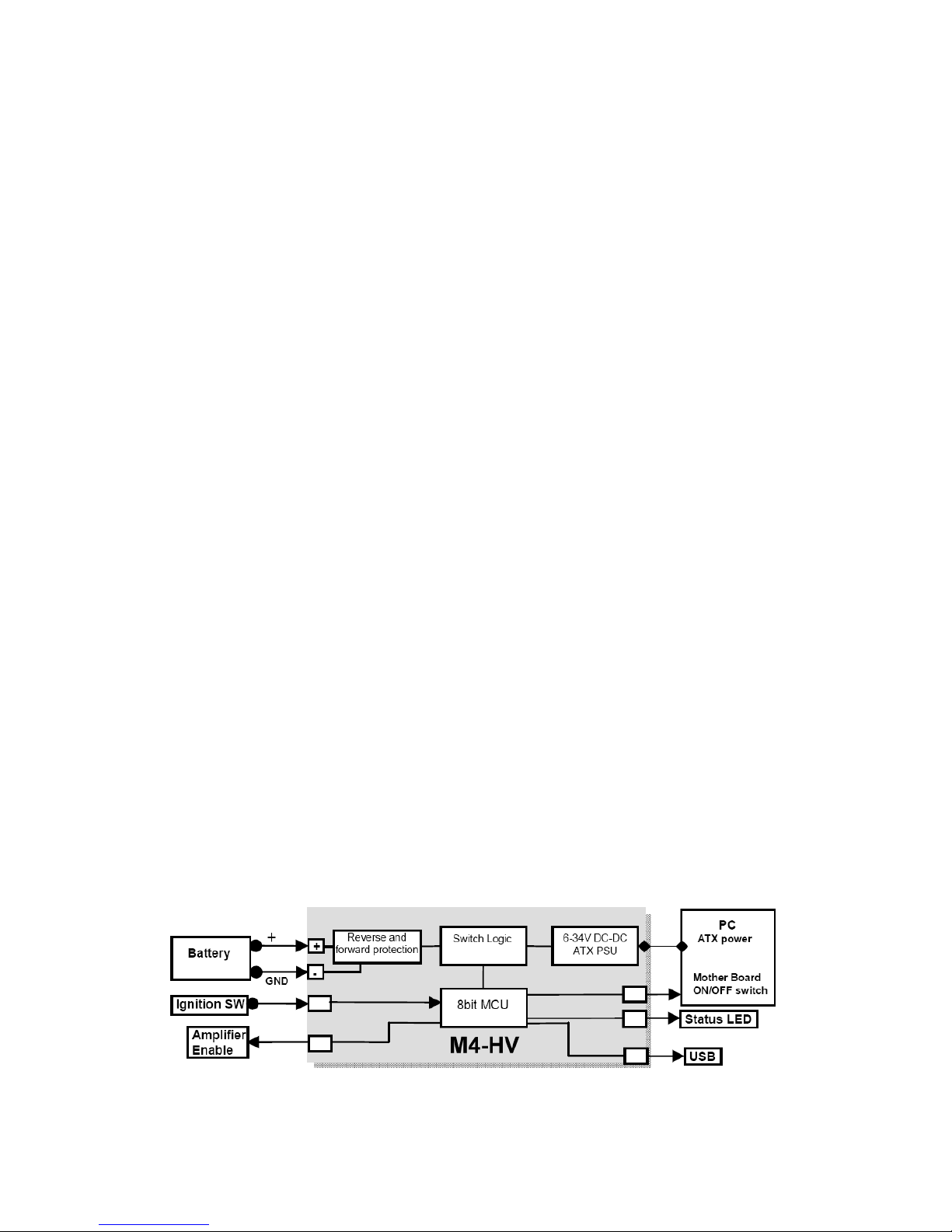
Power challenges in a Vehicle PC:
One of most difficult tasks of operating a PC in a vehicle is power consumption while the
computer is OFF. Even when your computer is OFF or in Suspend, it will still consume about
50-150mA on the 5VSB rail.
No matter how big your battery is, you will eventually drain it if proper actions are not taken.
The M4- V ATX is addressing these issues by cutting off the 5VSB rail after a pre-defined
amount of time (see jumper chart, ARDOFF). During the ARDOFF if the battery level drops
below 11.2V for more than one minute, M4- V ATX will shut down and re-activate only when
the input voltage is > 12V.
Engine Cranks, under-voltage and over-voltage situations.
Another difficult task is maintaining stable power to your PC. While car batteries are rated at
12V, they actually provide voltages in between 8-16V (engine cranks) or as high as 80 volts
(load dump).
Most of the times, your battery will stay at 13.5V (while car is running) but extra precautions
need to take place in order to prevent such situations. M4- V ATX can operate as low as 6V
and as high as 34V while providing strict regulation on all rails along with input voltage
clamping and reverse protection.
Loud am lifier o s when PC starts (Anti-Thumb).
If your PC is connected to your car amplifier, you will hear a loud pop when the computer is
first started. The M4- V ATX has an `anti-thump' control that will keep your amp OFF while
the PC starts. Simply connect the 2 pin wire to J6 harness to your amplifier remote control
pins. The pin at the edge of the PCB is GND, inner pin is OT.
Mode of o eration
1. Ignition=OFF. Nothing happens. M4- V ATX is waiting for ignition signals.
2. Ignition=ON. M4- V ATX waits for 2-3 seconds then turns on the 5Vsb rail. After
another second M4- V ATX sends an "ON" signal to the motherboard via the 2 wires
connected to the motherboard's ON/OFF pins. The motherboard will turn ON and your
system should start booting. The Ignition state will be latched for 60 more seconds so
that the motherboard will have a change to come up in a clean manner.
3. Ignition=ON. Your computer will remain ON.
4. Ignition=OFF. M4- V ATX waits for "OFFDELAY" in seconds (see jumper chart) and then
it turns the motherboard OFF by sending a signal to the motherboard's ON/OFF switch.
Your computer should turn off gracefully (shutdown procedure). After shutdown, 5VSB
will still be provided for another " ARDOFF" seconds. In the event where the shutdown
process is longer than " ARDOFF" (Operating System gets frozen, etc), power will be
shut down hard, turning off all power rails. During the ARDOFF procedure, the battery
levels will be constantly monitored to prevent deep discharge situations.
5. M4- V ATX will go to step 1, if ignition is tuned ON again.
4

NOTE. When all config. jumpers are removed, M4- V ATX acts as a regular power supply, no
ignition timing, no ARDOFF. M4-ATX- V will also send a gratuitous “ON” pulse (to the
ON/OFF motherboard pins, should you have a wire harness connected to it) when power is
applied for the first time. Do not connect the on/off switch if you don’t want your PC to be
started automatically.
Troubleshooting
a)
Motherboard is not turning ON: Check input cables.Make sure you have a a well
tighten wire harness. Measure the un-switched pin (red). You should see 12V (car on)
or 0V (car off). NOTE: In P1, P2, P3 modes if V(In) is < 12V, the M4- V ATX will not
start.
b)
Motherboard is not turning ON (cont): Ensure total system power consumption
does not exceed the M4- V ATX specifications.
c)
Motherboard is not turning ON (cont). Make sure that the ON/OFF wire harness
from the M4- V ATX is connected to the ON/OFF switch of your M/B.
5

M4-HV ATX Characteristics
Minimum Input Operating. voltage 6V
Maximum input Operating voltage 34V (clamping will occur at 36-38V)
Deep-Discharge shutdown threshold 11.2V
Input current limit (fuse protected) Mini-Blade 25 A
Max Output Power 220 Watts (275 Watts PEAK)
Deep Sleep Current Consumption. < 1.6 mA
Storage and operating temperature -40 to +125° Celsius (storage), -40 – 65°C (operating)
MTBF 200,000 hrs
Efficiency (Input 9-16V) >94%, all rails combined, 50% load
Input connectors M4 screw terminal
Output Connector ATX Power 24 pin (Molex P/N 39-01-2200)
*Units shuts down when internal temperature sensor indicates >85°C. This value can be changed with software.
Operating at temperatures above 85°C will reduce the MTBF.
Maximum Power Characteristics
Output Rail Current (Max) Current Peak
(< 30 seconds)
Regulation
5V 12A 15A 1.5%
3.3V 12A 15A 1.5%
5VSB 1.5A 2A 1.5%
-12V 0.15A 0.2A 10%
12V 10A (see below) 12A (see below) 2%
When operating at <8V or >16V or extreme temperatures, de-rate by 25-50%, ventilation will be required. When
operating at constant 160watts or more forced ventilation is required.
12V Rail Out ut Current (buck/boost converter)
Input (V) 12V out current Input (V) 12V out current
6-8V 8A 11-16V 10A (12A peak)
8-11V 10A (12A peak) 16-34V 8A (10A peak)
6
Table of contents
Other mini-box Power Supply manuals

mini-box
mini-box M3-ATX-HV User manual

mini-box
mini-box M4-ATX-HV User manual

mini-box
mini-box M4-ATX User manual

mini-box
mini-box M2-ATX User manual

mini-box
mini-box M4-ATX User manual

mini-box
mini-box M2-ATX User manual

mini-box
mini-box picoPSU-80-WI-32 User manual

mini-box
mini-box M3-ATX User manual

mini-box
mini-box M1-ATX User manual

mini-box
mini-box M2-ATX-01 User manual
Popular Power Supply manuals by other brands

Puls
Puls PIANO PIM60.241 manual

BCP
BCP PUOOOBK How to install

Newcastle Systems
Newcastle Systems PowerPack Ultra 2.6 series owner's manual

Baumuller
Baumuller BUG 622 manual

Delta Elektronika
Delta Elektronika SM15K Series product manual

Heritage MedCall
Heritage MedCall HM-535 Installation and service instructions