Autonics ARIO-C-EI User manual

Coupler manual
Field Network Devices
ARIO-C-EI (Ethernet/IP)
Thank you for purchasing an Autonics product.
This user manual contains information about the product and its proper use,
and should be kept in a place where it will be easy to access.
www.autonics.com
MOO-ARIOCEIU-V1.2-2103US

© Copyright Reserved Autonics Co., Ltd. iii

ii © Copyright Reserved Autonics Co., Ltd.

Preface
© Copyright Reserved Autonics Co., Ltd. iii
Preface
Thank you for purchasing Autonics product.
Please familiarize yourself with the information contained in the Safety Considerations section
before using this product.
This user manual contains information about the porduct and its proper use, and should be kept in
a place where it will be easy to access.

Coupler Manual Guide
iv © Copyright Reserved Autonics Co., Ltd.
CouplerManualGuide
Please familiarize yourself with the information in this manual before using the product.
This manual provides detailed information on the product's features. It does not offer any
guarantee concerning matters beyond the scope of this manual.
This manual may not be edited or reproduced in either part or whole without permission.
This manual is not provided as part of the product package.
Please visit our website (www.autonics.com) to download a copy.
The manual's content may vary depending on changes to the product's software and other
unforeseen developments within Autonics, and is subject to change without prior notice.
Upgrade notice is provided through our homepage.
We contrived to describe this manual more easily and correctly. However, if there are any
corrections or questions, please notify us these on our website.

Coupler Manual Symbols
© Copyright Reserved Autonics Co., Ltd. v
CouplerManualSymbols
Symbol
Description
Supplementary information for a particular feature.
Failure to follow instructions can result in serious injury or death.
Failure to follow instructions can lead to a minor injury or product damage.
An example of the concerned feature’s use.
※1
Annotation mark.

Safety Considerations
vi © Copyright Reserved Autonics Co., Ltd.
SafetyConsiderations
Please observe all safety considerations for safe and proper product operation to avoid
hazards.
Safety considerations consist of ‘warning’ and ‘caution. The following symbols represent
caution due to particular circumstances in which hazards may occur.
Warning
Failure to follow instructions can result in serious injury
or death.
Caution
Failure to follow instructions can lead to a minor injury
or product damage.
Fail-safe device must be installed when using the unit with machinery that may cause serious
injury or substantial economic loss. (e.g. nuclear power control, medical equipment, ships,
vehicles, railways, aircraft, combustion apparatus, safety equipment, crime/disaster
prevention devices, etc.)
Failure to follow this instruction may result in personal injury, economic loss or fire.
Do not use the unit in the place where flammable/explosive/corrosive gas, high humidity,
direct sunlight, radiant heat, vibration, impact, or salinity may be present.
Failure to follow this instruction may result in explosion or fire.
Do not disassemble or modify the unit.
Failure to follow this instruction may result in fire.
Do not connect, repair, or inspect the unit while connected to a power source.
Failure to follow this instruction may result in fire.
Check ‘Connections’ before wiring.
Failure to follow this instruction may result in fire.
Use the unit within the rated specifications.
Failure to follow this instruction may result in fire or shortening the life cycle of the product.
Use a dry cloth to clean the unit, and do not use water or organic solvent.
Failure to follow this instruction may result in fire or electric shock.
When connecting the power input and I/O wiring, use AWG 22~16 cable.
After checking the connecting and removing the wire, use the crimp terminal.
Failure to follow this instruction may result in fire or malfunction due to contact failure.
Keep the product away from metal chip, dust, and wire residue which flow into the unit.
Failure to follow this instruction may result in fire or product damage.
Do not cut off power or disconnect connectors (or terminals) while operating the unit.
Failure to follow this instruction may result in fire or product damage.
The specifications and dimensions of this manual are subject to change without any notice

Caution during Use
© Copyright Reserved Autonics Co., Ltd. vii
CautionduringUse
Follow instructions in ‘Caution during Use’. Otherwise, it may cause unexpected accidents.
ABUS power and I/O power should be insulated by the individually insulated power device.
Power supply should be insulated and limited voltage/current or Class 2, SELV power supply
device.
Use the rated standard cables and connectors. Do not apply excessive power when connecting
or disconnecting the connectors of the product.
Keep away from high voltage lines or power lines to prevent inductive noise.
In case installing power line and input signal line closely, use line filter or varistor at power line
and shielded wire at input signal line.
For the stable operation, use shield wire and ferrite core, when wiring communication wire,
power wire, or signal wire.
Do not use near the equipment which generates strong magnetic force or high frequency noise.
Do not touch the module communication connecter part of the base.
Do not connect or remove the base while connected to a power source.
For removing the terminal, body or base, do not operate units for a long time without it.
This unit may be used in the following environments.
①Indoors
②Altitude max. 2,000m
③Pollution degree 2
④Installation category II

Table of Contents
viii © Copyright Reserved Autonics Co., Ltd.
TableofContents
Preface........................................................................................................................................iii
Coupler Manual Guide..............................................................................................................iv
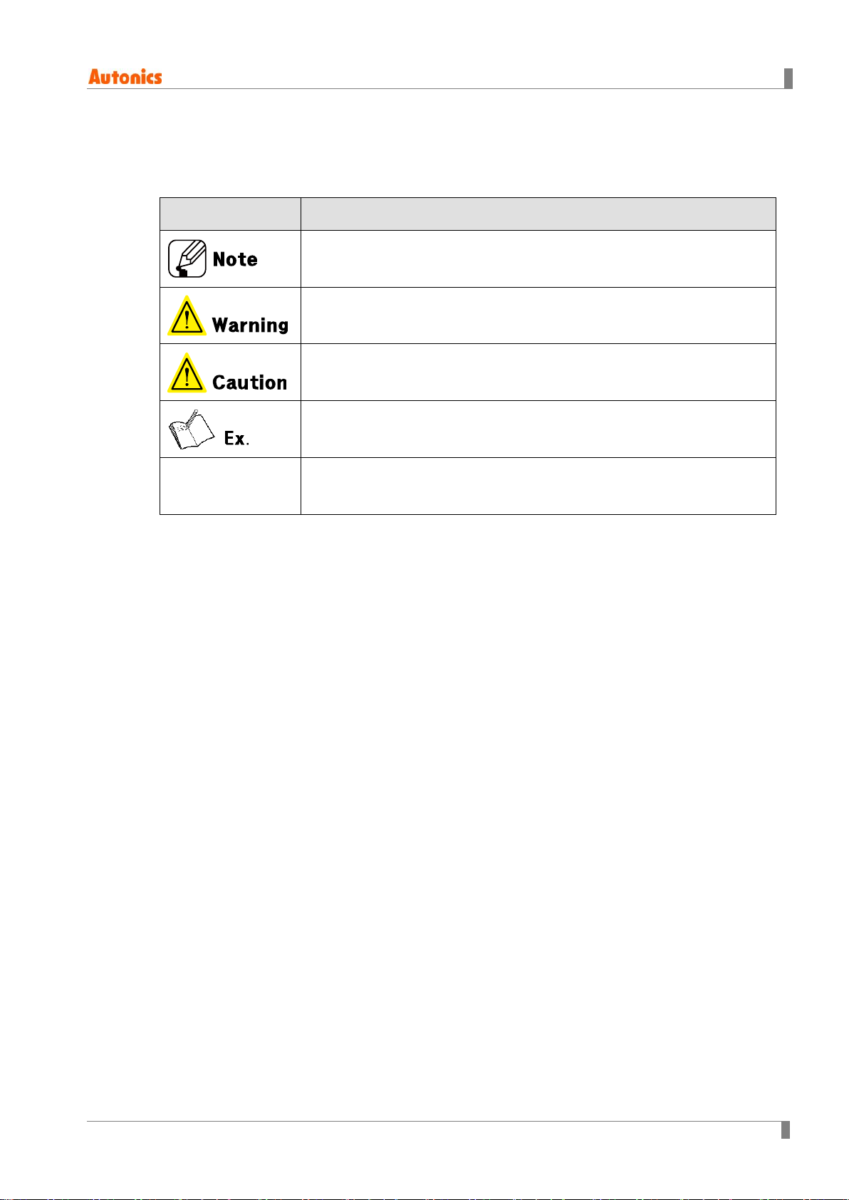
Coupler Manual Symbols..........................................................................................................v
Safety Considerations ..............................................................................................................vi
Caution during Use ..................................................................................................................vii
Table of Contents....................................................................................................................viii
1Reference manuals .....................................................................10
1.1 Instruction manual.....................................................................................................10
1.2 Coupler manual..........................................................................................................10
1.3 Module manual...........................................................................................................10
1.4 DAQMaster user manual............................................................................................10
2Protocol overview.......................................................................11
2.1 EtherNet I/P.................................................................................................................11
3Specifications.............................................................................12
4Hardware ...................................................................................14
4.1 Dimensions..................................................................................................................14
4.2 Unit descriptions ........................................................................................................15
4.3 Rotary switch for communication setting ..............................................................16
4.3.1 Transfer rate........................................................................................................ 16
4.3.2 Switch for station no.......................................................................................... 16
4.4 Wiring diagram for power supply.............................................................................16
4.5 Status indicator ..........................................................................................................17
5Memory map ..............................................................................19
5.1 Memory system...........................................................................................................19
5.1.1 Data handling...................................................................................................... 19
5.1.2 Data type.............................................................................................................. 19
5.2 Memory structure .......................................................................................................20
5.3 Memory area................................................................................................................21
5.4 Gather diagnostic information of modules............................................................21
5.5 Process image.............................................................................................................22
5.6 Example of memory map..........................................................................................22
5.6.1 Device................................................................................................................... 22
5.6.2 Input process image .......................................................................................... 23
5.6.3 Output process image ....................................................................................... 23

Table of Contents
© Copyright Reserved Autonics Co., Ltd. ix
6Diagnosis function...................................................................... 24
6.1 Overview......................................................................................................................24
6.2 Diagnostic type...........................................................................................................24
6.3 Definition.....................................................................................................................25

1 Reference manuals
10 © Copyright Reserved Autonics Co., Ltd.
1Reference manuals
1.1 Instruction manual
It describes an overview of Remote I/O, definitions of terms, installation environment,
mounting/removing method, wiring and troubleshooting.
1.2 Coupler manual
It describes the overview, specification, demensions, memory map and troubleshooting of each
communication.
1.3 Module manual
It describes the demensions, specification, connections and diagnosis function of each module
1.4 DAQMaster user manual
DAQMaster, a device integration management program, provides the expanded user convenience.
You can use the module setting, real-time control, and monitoring/diagnosis function of
input/output signal (except ARIO-C-PN and ARIO-C-PB). Also, you can arrange products through
virtual mode and recommended sorting.

2 Protocol overview
© Copyright Reserved Autonics Co., Ltd. 11
2Protocol overview
2.1 EtherNet I/P
EtherNet/IP is an industrial network protocol thatapplies a universal industrial protocol to the standard
Ethernet. That is, the EhterNet/IP has great flexibility is made by usingthe CIP protocol used in DeviceNet
andControlNet, which are ODVA fieldbus networks of the same association.
ARIO-C-EI, EtherNET/IP Coupler, integrates data from allconnected I/O modules with EtherNET/ IP. The
coupler determines the physicalstructure of the node and automatically creates a local process image
of all the I / O. Italso includes amixed arrangement of analog (word) anddigital(byte) modules.
The process image is divided into inputand output data areas.

3 Specifications
12 © Copyright Reserved Autonics Co., Ltd.
3Specifications
Model
ARIO-C-EI
Coupler type
Ethernet/IP
Power
supply※1
ABUS(external
consump.)
24VDCᜡ, max. 400mA
(max. 9.6W, coupler+module, max. 200mA/CH, 2CH/COM)
ABUS(internal
supply)
5VDCᜡ, max. 960mA
(max. 4.8W, module)
I/O
24VDCᜡ, max. 4,000mA
(max. 96W, max. 2,000mA/CH, 2CH/COM)
Power
consumption
Coupler
24VDCᜡstandby/run: 200mA,
Max. load: 400mA (coupler max. load)
Internal
communication
Protocol
ABUS protocol
Transmission
speed
4Mbps only
Memory※2
Input
504 byte
Output
504 byte
Max. connections for modules※2
64 units (max. length is up to 768mm)
Higher-level
protocols
Transfer rate
10/100Mbps
Distance
between Nodes
Max. 100m
Communication
connector
RJ45 connectors (min.CAT5e)
Concurrent
connection of
Node
Depending on the specifications of Ethernet
Node setting
Rotary switch for communication setting in ARIO (Station no.)
Topology
Bus, Line, Star
Operating
mode
Level 2 I/O Server (Explicit, I/O Message)
Installation method
DIN rail mounting
Setting and monitoring
PC connection with USB 2.0 Micro type connector
(comprehensive device management program, DAQMaster)

3 Specifications
© Copyright Reserved Autonics Co., Ltd. 13
Model
ARIO-C-EI
Insulation resistance
Over 100MΩ(at 500VDCᜡmegger)
Dielectric strength
1000VAC 50/60Hz for 1 min
Noise immunity
±500V the square wave noise (pulse width: 1 ㎲) by the noise simulator
Vibration
Mechanical
0.7mm amplified at frequency of 10 to 55Hz (for 1 min) in each X, Y, Z
direction for 1 hour
Malfunction
0.5mm amplified at frequency of 10 to 55Hz (for 1 min) in each X, Y, Z
direction for 10 min.
Shock
Mechanical
300m/s² (approx. 30G) in each X, Y, Z direction for 3 times.
Malfunction
100m/s² (approx. 10G) in each X, Y, Z direction for 3 times.
Environment
Ambient temp.
-10 to 55℃, storage: -25 to 70℃
Ambient humi.
35 to 85%RH, storage: 35 to 85%RH
Protection structure※3
IP20 (IEC standards)
Material
Terminal: polyamide6, Body: modified polyphenylene oxide,
Base: polyamide6, poly oxy methylene
Approval
Association approval
Weight※4
Approx. 265g (approx. 165g)
※1. It is including power/special modules and excluding coupler/end modules. In case of one coupler module
connecting, the ARIO digital module is available to connect up to 8 units, and the ARIO analog and special
modules are available to connect up to 4 units. For connecting the modules, consider power concumption of
the sensors and drivers connected the ARIO coupler.
※2. If it over the limit size or connected units, system may be error.
※3. Autonics test standard
※4. The weight includes packaging. The weight in parenthesis is for unit only.
※Environment resistance is rated at no freezing or condensation.

4 Hardware
14 © Copyright Reserved Autonics Co., Ltd.
4Hardware
4.1 Dimensions
(1) Coupler
(2) End module

4 Hardware
© Copyright Reserved Autonics Co., Ltd. 15
4.2 Unit descriptions
1. Communication connector: RJ45 connector
You can use a universal Ethernet connector / cable (Category 5E), but we recommend using
connectors and cables that are certified by the EtherNet / IP Association (ODVA).
2. Communication setting switch (station no: X16, X1)
3. Setting connector (USB 2.0 type Micro B)
: You can connect DAQMaster to configure and monitor.
4. Indicators for power and comm. status
4-1 Internal / external state of coupler: Displays the input power / operation state of the
coupler.
4-2 State of Field network: Displays the operation of the field network.
5. Power terminal block
6. ABUS comm. connector: Input terminal that supplies circuit driving power of the coupler,
ABUS, and modul by receiving 24VDC.
I/O power supply: Supplies power for input / output signal of module by receiving DC, AC, etc.

4 Hardware
16 © Copyright Reserved Autonics Co., Ltd.
4.3 Rotary switch for communication setting
4.3.1 Transfer rate
Based on the network quality, Auto-Negotiation is performed to determine 10 / 100Mbps.
4.3.2 Switch for station no.
Switch
Description
Station no.: X16
Use to distinguish theorder (name) of couplers.
Range: 01 to255
Station no.: X1
The rotary switch cannot be changed while the power is operating. Toapply the changed rotary switch,
the coupler mustbe turned on again.
The switch for station number can change the last 3of the IP address '192.168.2.3' that the coupler saves.
You can also change the IP address arbitrarily via DAQMaster.
[Example] ‘12h' of the switch means '192.168.2.18'.
However, ifsettings of switches are all '00', the stationnumber (IP address)is set based on the
information that the coupler saves.
4.4 Wiring diagram for power supply
Terminal No.
Descriptions
1, 7
System Power (24VDC)
2, 8
System Power (0VDC)
3, 9
N.C. (Not Connected)
4, 10
Field Power (24VDC, POS)
5, 11
Field Power (0VDC, NEG)
6, 12
Frame Ground / Shield

4 Hardware
© Copyright Reserved Autonics Co., Ltd. 17
4.5 Status indicator
(1) Definition
Indicator
Color
ON
OFF
POWER
Green
Thepower voltage of coupler is connected.
(supply 24VDC)
No powersupply
SYSTEM
Green
Normaloperation
(deviceon online state, communicatingwith
master)
Stopoperation
Red
Failuretoinitializecoupler (recovery failed)
Recovery error during the coupler operation
(recoveryfailed)
Difference between field network type and
firmwareversion(recovery failed)
Normal operation
DIAG
Green
Normaloperation (Multi Packet and Single Packet
are operating)
Stop operation of coupler
or in error condition.
Red
Internal network (ABUS) inoperablestate
Normal operation
IO POWER
Green
The I/O power voltage of coupler is connected.
No powersupply
(2) Status
Indicator
Color
Flashing
Flashing 1
Flashing 2
Flashing 3
Flashing 4
POWER
Green
ㅡ
ㅡ
ㅡ
ㅡ
ㅡ
SYSTEM
Green
Wait for connecting
themaster after
couplerinitialization
completes
ㅡ
ㅡ
ㅡ
ㅡ
Red
Change during
Initializing coupler
or rotary switch
operation
Field network
initialization failed
(recoveryfailed)
ㅡ
ㅡ
ㅡ
ㅡ
DIAG
Green
Hot-swap state
(normalstate)
ㅡ
ㅡ
ㅡ
ㅡ
Red
Module,which
differentfromthe
removed module,is
inserted.
(normaloperation)
ㅡ
Initialization
failure:
There isno
connected
module.(rec
overy failed)
Initialization
failure:
abnormal
module is
operating
(recovery
failed)
Initialization
failure:
maximum
module /
data size
exceeded
IO POWER
Green
ㅡ
ㅡ
ㅡ
ㅡ
ㅡ

4 Hardware
18 © Copyright Reserved Autonics Co., Ltd.
Following chart is a timing diagram of flashing -/1/2/3.
(3) Status of field network
LED
Color
Status
Description
MS
ㅡ
OFF
No power
Green
Flashing
Standby: Nodeviceconfiguration
ON
The device is operating
Red/Green
Flashing
Self-diagnostic: powertest
Red
Flashing
Configurationerror
ON
Recovery error
NS
-
OFF
No power, no IPaddress
Green
Flashing
No device connection, IPaddressexists
ON
One or more connections completed (including MessageRouter)
Red/Green
Flashing
Self-diagnostic: powertest
Red
Flashing
One or more connection timeouts (Reset is required)
ON
A duplicate IP address exist

5 Memory map
© Copyright Reserved Autonics Co., Ltd. 19
5Memory map
5.1 Memory system
5.1.1 Data handling
classification
I/O type
Method of data handling
Bit
2 point/module
1 byte
4 point/module
1 byte
8 point/module
1 byte
16 point/module
2 byte (= 1word)
Byte
8 bit/channel
1 byte
12 bit/channel
2 byte (= 1word)
16 bit/channel
2 byte (= 1word)
24 bit/channel
4 byte (= 2word)
The module manages arbitrarily transformed databased on its input/outputtype.Itmakes a waste of
memory size, however, register position (such as PLC) can be easily calculated because the estimates of
the dataposition are separated intothe modules.
5.1.2 Data type
The data type can be expressed in the way of bit or byte unit. If the IO type is smaller than the
method of data handling, the empty space of data is filled with 0. You can also set the arrangement
method of analog data to Big Endian or Little Endian via DAQMaster.
- Bit unit: The value of the corresponding bit is expressed as '1'
- byte unit: The input value is expressed in each byte
- Factory settings of the coupler: Big Endian
Data unit is the Bit, point 3 of the digital input module received the input signal
- Data expression: 0b 0000 0100 (0x04) (□□□□□■□□ = 0x04)
Data unit is the byte, channel 1 of the analog input module received the input signal with
10.000V
- Big Endian: 0x 27 10 (10,000)
- Little Endian: 0x 10 27 (4,135)
When the handling data of ARIO-S-DI04P is 4 bits
- The input type of the module above is 4 bits, and the value is smaller than 1 byte (8 bit), which
is the data handling method. So the coupler fills the □area of □□□□BBBB with the
number 0.
- Data expression: 0b 0000 BBBB
Table of contents
Other Autonics Power Supply manuals
Popular Power Supply manuals by other brands

SilverStone
SilverStone ST50NF user manual

BEHLMAN
BEHLMAN BL20000 Series User's guide and technical reference manual

GlobTek
GlobTek GTM96300-3036-6.0-R2 Operating lnstructions

Linear Technology
Linear Technology DEMONSTRATION CIRCUIT 470 quick start guide

TONGHER
TONGHER TH-Mars 2 Installation and user manual

TDK-Lambda
TDK-Lambda HWS 1500/ME Series instruction manual

GE
GE Infinity M Series installation guide

GAMDIAS
GAMDIAS KRATOS M1-600B Quick installation guide

Puls
Puls PIANO PIM60.241 manual

Cooler Master
Cooler Master RS-600-ASAA user manual

Delta Elektronika
Delta Elektronika SM15K Series product manual

National Instruments
National Instruments NI PXI-1006 user guide