Autonics GP-S070 User manual

R-17
(A)
Photo
electric
sensor
(B)
Fiber
optic
sensor
(C)
Door/Area
sensor
(D)
Proximity
sensor
(E)
Pressure
sensor
(F)
Rotary
encoder
(G)
Connector/
Socket
(H)
Temp.
controller
(I)
SSR/
Power
controller
(J)
Counter
(K)
Timer
(L)
Panel
meter
(M)
Tacho/
Speed/ Pulse
meter
(N)
Display
unit
(O)
Sensor
controller
(P)
Switching
mode power
supply
(Q)
Stepper
motor&
Driver&Controller
(R)
Graphic/
Logic
panel
(S)
Field
network
device
(T)
Software
(U)
Other
Graphic Panel
7 inch TFT Color LCD
Features
7 inch wide screen, TFT Color LCD type
Graphic touch panel GP-S070
Manual
Visit our webwite(www.autonics.com) to download 'GP Editor user manual' or 'GP, LP user manual for communication',
'GP-S070 user manual'.
● GP Editor user manual
It describes how to write screen data, and is about related usage of GP-S070 HMI function.
● GP, LP user manual for communication
It describes connection for external devices such as PLC.
● GP-S070 user manual
It describes general information on the installation and usage of GP-S070 and system contents.
● Adopts 7 inch wide TFT LCD for realizing
True Color with 16,777,216 colors
● Analog touch method
: Free tag arrangement than matrix touch method
● Data logger function
: Supports data gathering and backup of controller
● Supports variable image library
● Enables to monitor multi station and multi channel at
the same time
● Supports several interface
: Supports USB Host/Device to high speed download and
manage les
: Easy to connect various external devices with RS232C 2 ports
and RS232C/RS422 multi-communication port
● Supports several fonts: Supports window true type and several bitmap fonts (selectable)
● Device monitoring function
: Enables to monitor/control variable of connected control through communication port
● Easy S/W upgrade at website
(1) GP rmware le
(2) GP Editor (drawing program)
(3) Additional protocol
(4) Language and font, etc
● Connects printer/barcode reader: Enables to print out alarm history, to read barcode
NEW
Ordering information
Model Item Series Monitor size Display unit Color Power supply Interface
GP-S070-T9D6 Graphic
panel S series 7 inch TFT Color
LCD
16,777,216
color 24VDC
RS232C, RS422, USB HOST,
USB DEVICE, Ethernet
GP-S070-T9D7 RS232C (2EA), USB HOST
USB DEVICE, Ethernet
Please read “Caution for your safety” in operation
manual before using.
GP-S070

R-18
GP-S070
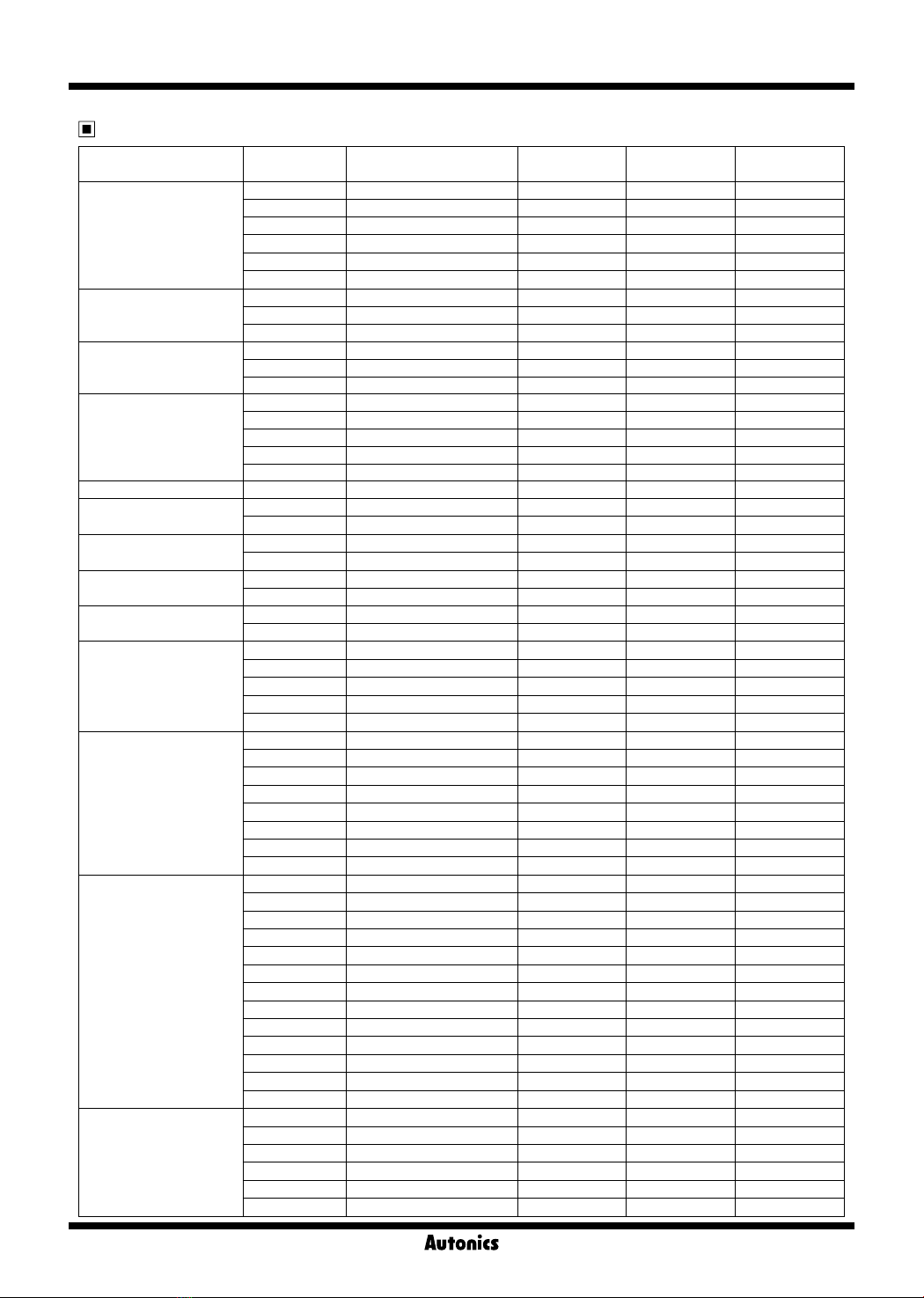
Model GP-S070-T9D6 GP-S070-T9D7
Power supply 24VDC
Allowable voltage range 90 to 110% of power supply
Power consumption Max. 7.2W
Display performance
LCD type 7 inch TFT Color LCD
Resolution 800×480 dots
Display area 152.4mm×94.44mm
Color 16,777,216 color
LCD view angle Within each 50°/ 60°/ 65°/ 65°of top/bottom/left/right
Backlight White LED
Brightness Adjustable by software
Graphic drawing
performance
Language※1English, Korean
Text • Vector font • 6×8, 8×8 ASCII character, high denition numbers
• 8×16 ASCII characters, 16×16 regional characters(1 to 8 times bigger for width, 0.5 to 5 times bigger for height)
Graphic drawing memory 16MB
Number of user screen 500 pages
Touch switch Analog touch
Serial interface Asynchronous method: Each port of RS232C, RS422
Each port of RS232C, RS422 Two ports of RS232C
USB interface Each of USB HOST, USB Device(Version 1.1)
Ethernet interface IEEE802.3(U), 10/100Base-T
Real-time controller RTC embedded
Battery life cycle Approx. 3 years at 25℃
Insulated resistance Min. 100MΩ(at 500VDC megger)
Ground 3rd grounding(max. 100Ω)
Noise resistance ± 0.5kV the square wave noise(pulse width: 1㎲) by the noise simulator
Withstanding voltage 500VAC 50/60Hz for a minute
Vibration Mechnical 0.75mm amplitude at frequency of 10 to 55Hz(for 1 min.) in each of X, Y, Z directions for 1 hour
Malfunction 0.5mm amplitude at frequency of 10 to 55Hz(for 1 min.) in each of X, Y, Z directions for 10 min.
Shock Mechanical 300m/s²(approx. 30G) in each of X,Y,Z directions for 3 times
Malfunction 100m/s²(approx. 10G) in each of X,Y,Z directions for 3 times
Environ
-ment
Ambient temperature 0 to 50℃, storage: -20 to 60℃
Ambient humidity 35 to 85% RH, storage: 35 to 85%RH
Protection IP65F for front panel
Accessory Fixing bracket: 4EA, Battery(included)
Approval
Unit weight Approx. 520g
Figure display Line, rectangle, circle, text, bitmap
Tags
Numeral display Displays the designated device as numerical value.(decimal, hexadecimal, octal, binary, real number)
ASCII display Displays the designated device value as ASCII character.
Time display Displays current time or date.
Alarm history Registers alarm history.
Alarm list Displays generated (not backed up) alarm.
Comment display Displays the designated comment as device status or value.
Lamp Displays lamp as device status.
Part display Displays the designated parts as device status and value.
Line graph Displays several device values with a graph of broken line.
Trend graph Displays change of device value for time with a graph of broken line.
Bar graph Displays a device value with a bar graph.
Statistic graph Displays a ratio of several device values with pie graph.
Panel meter Displays a device value as panel meter.
Touch key Screen is switched, word/bit device values are set when it touched.
Numeral input Congures user input value in device.
ASCII input Congures user input ASCII code value in device.
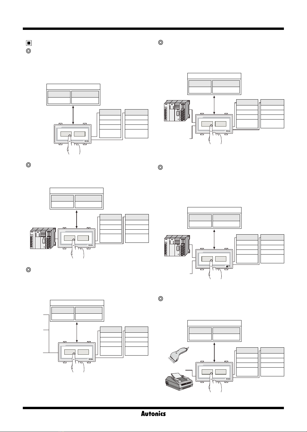
System information function Monitors/Controls GP operation from PLC.
Recipe function Reads/Writes several PLC device collectively.
Security function Only acceptable user can observe/operate important data.
Barcode read function Connects barcode reader, read barcode.
Floating alarm function Warning message is oated when alarm is generated.
Time operation Specic bit device is ON/OFF for designated day and time.
Overlap window Available to form dynamically overlapping another base screen on the base one.
Observe status function Changes PLC device status/value of PLC when trigger is generated.
※1: Language can be customized.
※Environment resistance is rated at no freezing or condensation.
Specifications
Functional description

R-19
(A)
Photo
electric
sensor
(B)
Fiber
optic
sensor
(C)
Door/Area
sensor
(D)
Proximity
sensor
(E)
Pressure
sensor
(F)
Rotary
encoder
(G)
Connector/
Socket
(H)
Temp.
controller
(I)
SSR/
Power
controller
(J)
Counter
(K)
Timer
(L)
Panel
meter
(M)
Tacho/
Speed/ Pulse
meter
(N)
Display
unit
(O)
Sensor
controller
(P)
Switching
mode power
supply
(Q)
Stepper
motor&
Driver&Controller
(R)
Graphic/
Logic
panel
(S)
Field
network
device
(T)
Software
(U)
Other
Graphic Panel
185
194
Fixing bracket
(2 slots is in upper side, 2 slot is in lower side)
Power terminal
block
LCD Screen RS422
or
RS232C
-A
USB
Device
USB
Host
Ethernet
RS422
or
RS232C
-B
M4 BOLT
Max. 4-R3
15
Min. 240
※Panel thickness
: Max. 4mm
6.5 28.5
134
125
146
Min. 175
Mounting slot
for bracket
● Panel cut-out
● Fixing bracket
(unit : mm)
Dimensions
186 +1.1
0
126 +1.0
0
Part description
● Ethernet Port: For connecting LAN cable and hub, use direct cable, and for connecting PC directly, use cross cable.
● USB Device: It is used to upload and download project (it is required to install USB driver on PC), and when connect
to PC, it can be used as a USB memory (PC recognizes it as a removable disk).
● USB Host: It is used to manage data and upgrade firmware.
● RS232C, RS422 ports: For more information, refer to R-32 page and ' Serial interface' of GP/LP common features.

R-20
GP-S070
(Upper side)
(Lower side)
M4 Screw driver
Mounting slot
for bracket
Installation
1. Set GP-S070 in panel.
2. Set fixing brackets in 4 slots(2 slots is in upper side, 2 slots is in lower side).
Sold separately
Transmission cables connectable into external devices such as PLC are sold separately. (refer to the R-32 page for "GP/
LP communication cable".)
3. Tighten fixing bracket with M4 Screw driver and tightening torque is 0.3 to 0.5N·m.

R-31
(A)
Photo
electric
sensor
(B)
Fiber
optic
sensor
(C)
Door/Area
sensor
(D)
Proximity
sensor
(E)
Pressure
sensor
(F)
Rotary
encoder
(G)
Connector/
Socket
(H)
Temp.
controller
(I)
SSR/
Power
controller
(J)
Counter
(K)
Timer
(L)
Panel
meter
(M)
Tacho/
Speed/ Pulse
meter
(N)
Display
unit
(O)
Sensor
controller
(P)
Switching
mode power
supply
(Q)
Stepper
motor&
Driver&Controller
(R)
Graphic/
Logic
panel
(S)
Field
network
device
(T)
Software
(U)
Other
GP/LP Common Features
24VDC
F.G.
+
+
-
-
Caution for using
Use communication cable after checking whether there is break, short.
Please install power switch or circuit-breaker in order to cut power supply off.
Separate this unit from high voltage line, power line to avoid inductive noise.
Do not use this product at below places.
Place where there is severe vibration or impact
Place where dust exists, or corrosion causing environments.
Place where strong magnetic field or electric noise are generated
Place where is temperature/humidity is beyond the specification
Place where strong alkalis or vibration or impact
Place where there are direct ray of the sun
Installation environment
It shall be used indoor.
Altitude Max. 2,000m
Pollution Degree 2
Installation Category Ⅱ
Serial interface
● All devices connectable into LP-S044 including PC, PLC, serial printer, barcode reader and dedicated connectors can be
connected into both RS232C and RS422 ports.
● Device must be set for the port in system setting for LP-S044, LP-S070. For details, refer to "GP user manual".
● Use the dedicated communication cable for the each connected device.
(Refer to the "GP/LP communication cable" of R-32 page)
● For the method of wiring external devices of PLC, refer to "GP/LP communication manual".
Power wiring
● For power supply, use the wire of which cross section is at least 0.75mm² and
use the wire of which cross section is at least 1.25mm² for grounding.
● Use crimp-on type terminal with at least 3mm of internal diameter and less than
6mm of external diameter.
● Do not apply power before power line connection.
● Check power polarity.
● Tighten the terminal screw with 0.5 to 0.8N·m torque.
● Ground resistance should be less than 100Ω and ground it separately.
Battery replacement
Please contact out distributor to replace battery.
It may cause an explosion or a fire when improper battery is used.
Port NO. Pin(GP-S044, GP-S057, GP-S070) Pin(LP-S044, LP-S070)
RS232C
D-Sub 9Pin
Male
1 Non-used Non-used
2 RXD RXD
3 TXD TXD
4 DTR DTR
5 SG SG
6 DSR DSR
7 Non-used Non-used
8 Non-used Non-used
9 Non-used Non-used
RS422
D-Sub 9Pin
Female
1 TXD+ TXD+
2 RXD+ RXD+
3 Non-used Non-used
4 Non-used Non-used
5 SG SG
6 TXD- TXD-
7 RXD- RXD-
8 Non-used Non-used
9 Non-used Non-used
5
4
3
2
1
5
4
3
2
1
9
8
7
6
6
7
8
9

R-2
General Features
GP-S044 GP-S057 GP-S070
The numerical value
of temperature
Graph of temperature
Control part GP-S044
GP-S044
GP-S044
GP-S044
GP-S044
PLC
PLC
PLC
PLC
Alarm is
occurred.
RS485
RS485
#1...........#32
Display temperature,
humidity
Printer
Thermometer/
hygrometer
Easy to set and
adjust parameter.
Alarm alert,
Preservation of history
GP(Graphic Panel)? Advantages of using GP
Preparation for using GP
Basic operation flow
Graphic panel is HMI(Human Machine Interface) device
that parameter monitors or changes via graphic interface
by communication with PLC, temperature controller or
other control units.
Graphic interface of GP is very effective to indicate value
or status of parameter with visual interface that enables the
communication between controller and user.
GP is able to monitor parameters virtually with LCD
screen, switch screen by touching screen, set or change
parameters. GP connecting with controller via serial
communication method translates data and displays
various control parameters with graphic.
For example, in case of the target of parameters is the
temperate, the numerical value of temperature is shown
with a tag and the change in temperature for time can be
graphed on the screen.
Complicated environment of operation
and control
It graphicalizes mechanical control components such as
button, switch and lamps so that saves cost and space and
improves the preservation of devices.
Setting and change of production
process
It graphicalizes mechanical control components such as
button, switch and lamps so that saves cost and space and
improves the preservation of devices.
Convenient setting by user
It sets complicated or non-displaying controller
(Thermometer/hygrometer, temperature controller etc).
1)Temperature/Humidity without display device
Effective data control
It prints alarm history of controller using printer. It reads the
data from barcode reader and save it in PLC.
1)PLC/Printer
2)Temperature controller
2)Barcode reader/PLC
Communication between heterogeneous
controllers
1) GP body
2) PC
3) GP Editor
- Software for drawing GP screen
4) Manual
- GP editor user manual
- LP, GP Communication manual
- GP-S044/S057, GP-S070 user manual
5) Communication cable
- Communication cable for PC connection
- Communication cable for controller connection
6) Access devices
(PLC or controller built in communication ports)
GP-S044Control part
Requirements
for using GP
Install GP Editor
on PC
Design data
with GP Editor
Download display
data to GP GP connect device
Start monitoring
Connection between
PC and GP body
<Refer to GP editer
user manual>
<Refer to GP, LP
communication manual>
<Refer to GP, LP
communication manual>

R-3
(A)
Photo
electric
sensor
(B)
Fiber
optic
sensor
(C)
Door/Area
sensor
(D)
Proximity
sensor
(E)
Pressure
sensor
(F)
Rotary
encoder
(G)
Connector/
Socket
(H)
Temp.
controller
(I)
SSR/
Power
controller
(J)
Counter
(K)
Timer
(L)
Panel
meter
(M)
Tacho/
Speed/ Pulse
meter
(N)
Display
unit
(O)
Sensor
controller
(P)
Switching
mode power
supply
(Q)
Stepper
motor&
Driver&Controller
(R)
Graphic/
Logic
panel
(S)
Field
network
device
(T)
Production
stoppage models
& replacement
(U)
Other
General Features
Requirements for using LP
Install drawing program (GP Editor) and
logic program (Smart Studio) on PC
Connection PC with LP body
※When LP turns on, RUN/STOP switch holds
STOP position.
Make Logic program with SmartStudio
Download logic data to LP body
Disconnect Smart Studio with LP body/
Connect GP Editor with LP body
Create screen or download to LP body
Test
※RUN/STOP switch holds RUN position.
Debugging or editing program
Control or start monitoring
LP-S044 LP-S070
PLC
HMI I/O <Refer to GP editer user manual and SmartStudio>
<Refer to communication manual>
<Refer to the SmartStudio programming manual>
※Refer to the manual for details on website(www.autonics.
com) resources.
Basic operation flow LP(Logic Panel)?
Logic panel is created for integrated panel in most
demanding industrial environments that have been
consisted of HMI, PLC and I/O. The LP through integration
realizes cost down, wire reduction, space saving and
enhanced user friendliness. The logic panel perfectly
supports serial communication and editing display with GP
Editor and about 250 commands of SmartStudio invented
on our own to edit PLC ladder/mnemonic, allowing
accelerating product development and designing. And also
this device can control and monitor various output devices
(sensors, button, etc) and output devices (solenoid, lamp,
motor, etc) individually.
Preparations for using LP
1) LP body
2) PC
3) Software
① GP Editor
- Software for drawing LP screen
② SmartStudio
- Software for logic program
4) Manual
- GP Editor user manual
- GP,LP Communication manual
- SmartStudio user manual
- SmartStudio programming manual
- LP-S044, LP-S070 user manual
- LP series command manual
5) Communication cable
- Communication cable for PC connection
- Communication cable for controller connection
6) Access device
(PLC or controller built in communication ports)

R-4
General Features
Run
Run
Run
Run
Run
Run
Stop
Stop
Stop
Stop
Stop
Stop
Download/
upload data
Download/
upload data
Download/
upload data
Download/
upload data
Download/
upload data
Download/
upload
data
A Controls
(PLC type)
Bar-code deader
Serial printer
A Controls(PLC type)
#1..................#31
Controls(PLC type)
#1
·
·
·
#2
#31
Controls
(Temperature
controller, etc)
B Controls
(Temperature controller, etc)
B Controls
(Temperature controller, etc)
PC
GP Editor
Drawing data
SmartStudio
Logic program
PC
GP Editor
Drawing data
SmartStudio
Control program
PC
GP Editor
Drawing data
SmartStudio
Control program
PC
GP Editor
Drawing data
SmartStudio
Control program
PC
GP Editor
Drawing data
SmartStudio
Control program
PC
GP Editor
Drawing data
SmartStudio
Control program
Input device
Button
Limit switch
Sensors
Other input
devices
Input device
Button
Limit switch
Sensors
Other input
devices
Input device
Button
Limit switch
Sensors
Other input
devices
Input device
Button
Limit switch
Sensors
Other input
devices
Input device
Button
Limit switch
Sensors
Other input
devices
Input device
Button
Limit switch
Sensors
Other input
devices
Output device
Solenoid
Lamp
Motor
Other output
devices
Output device
Solenoid
Lamp
Motor
Other output
devices
Output device
Solenoid
Lamp
Motor
Other output
devices
Output device
Solenoid
Lamp
Motor
Other output
devices
Output device
Solenoid
Lamp
Motor
Other output
devices
Output device
Solenoid
Lamp
Motor
Other output
devices
System configurations
Stand alone(LP Series)
Stand alone system in LP series controls a variety of I/
O without adding other devices and monitors and control
operation element through direct touch of screen. (device,
parameter, etc.)
1:1 configuration (LP/GP Series)
The device function makes it possible to monitor the
operation data (Device, parameter, etc.)
1:N configuration (LP/GP Series)
The device function makes it possible to monitor the
operation element (device, parameter, etc.) by connecting
in a 1:N configuration (Up to 32 units)
1:1:1 configuration (GP/LP Series)
The device function makes it possible to monitor,
control and the operation element (device, parameter,
etc.) between different devices using two separate
communication port.
1:1 N configuration (GP/LP Series)
The device function makes it possible to monitor,
control and the operation element (device, parameter,
etc.) between different devices using two separate
communication port.. In case of RS-422 port, 1:N is
available only. (Up to 31 units).
Bar-code, printer connection
(GP/LP Series)
It can read bar-code and print a history using printer.

R-5
(A)
Photo
electric
sensor
(B)
Fiber
optic
sensor
(C)
Door/Area
sensor
(D)
Proximity
sensor
(E)
Pressure
sensor
(F)
Rotary
encoder
(G)
Connector/
Socket
(H)
Temp.
controller
(I)
SSR/
Power
controller
(J)
Counter
(K)
Timer
(L)
Panel
meter
(M)
Tacho/
Speed/ Pulse
meter
(N)
Display
unit
(O)
Sensor
controller
(P)
Switching
mode power
supply
(Q)
Stepper
motor&
Driver&Controller
(R)
Graphic/
Logic
panel
(S)
Field
network
device
(T)
Production
stoppage models
& replacement
(U)
Other
General Features
Software
GP Editor(Drawing program)
Manual
GP/LP common manual
● GP Editor user manual
This section describes how to make screen data and use
HMI function with GP Editor.
● Communication manual
For more information of serial connection with external
devices such as PLC, refer to manual before connecting.
● GP-S044/S057, GP-S070 user manual
The manual describes installation and system organization
and menus.
LP manual
● SmartStudio manual
This section describes how to install and use
SmartStudio.
● Programming manual
The manual has command and instruction.
● LP-S044, LP-S070 user manual
The manual describes installation and system organization
and menus.
● LP Series instruction manual
The manual has LP installation, system configuration and
instruction.
Precaution for using
Do not press touch panel with hard and sharp object.
Please store the device in the recommended temperature
range, or LCD panel can be damaged.
Please check pin number shown in "Communication manual"
when connect communication port
Do not block the ventilating opening of this product.
Do not use or store it in a place with direct ray of light or dust.
Do not use or store it in a place with shock or vibration.
The ground wire of GP/LP should be grounded separately.
The ground resistance should be max. 100Ω, please use the
wire of min. 1.25mm² dimension.
Please check the pin number and connect to GP/LP
communication port.
Please tighten bolt on terminal block with specified tightening
torque.
When liquid crystal from the broken LCD is smeared on your
skin, wash it for 15 minutes. If it is gotten in your eye, wash
it for 15 minutes and contact a medical specialist for more
information.
Do not inflow dust or wire dregs into the unit.
For cleaning, do not use water or an oil-based detergent, use
dry towels.
It should be done away regarded as an industrial waste.
● This drawing software is for GP/LP series.
● GP Editor is the software that allows creating a screen
and designs a tag layout, and then transfer the data
from screen to GP/LP. After download, GP/LP starts
monitoring according to your screen data.
SmartStudio(Logic program)
● Logic software is for LP series.
● Support multi-project
: It is possible to open maximum 5 projects at a same
time.
● Easy program editing
: Block of cell units can be edited.
Split-screen editing is available.
It provides various editing screens such as variable
screen, describe screen, variable /describe screen, etc,.
● Various monitor functions
: It provides monitor functions such as variable monitor,
device monitor and system monitor, time chart.
● Comfortable user interface
: It ensures easy operation with Microsoft windows
layout.
● Wide range of Message windows
: It supports various message windows to edit and check
program.
● Real time convert ladder to mnemonic
: Ladder and mnemonic can be written and read to edit
simultaneously.
Visit our website (www.autonics.com) and download
software or manuals.
< System requirements >
Item Minimum requirements
System IBM PC compatible computer with Intel Pentium
Ⅲ or above
Operating system
Microsoft Windows 98/NT/XP/Vista/7
Memory 256MB or more
Hard disk More than 1GB of free hard disk space
VGA 1024×768 or higher resolution display
Others RS-232 serial port(9-pin), USB port

R-6
General Features
Series Connectable
device Connection type GP-S057 GP/LP-
S044
GP/LP-
S070
LS Master-K
MK-10S1 CPU direct connection loader ○ ○ ○
MK-80S CPU direct connection loader ○ ○ ○
MK-120S CPU direct connection loader ○ ○ ○
MK-200S CPU direct connection loader ○ ○ ○
MK-300S CPU direct connection loader ○ ○ ○
MK-1000S CPU direct connection loader ○ ○ ○
LS Glofa
GM4 CPU direct connection loader ○ ○ ○
GM6 CPU direct connection loader ○ ○ ○
GM7U CPU direct connection loader ○ ○ ○
LS CNET
(Cnet integrated CPU)
MK-80S Cnet ○ ○ ○
MK-120S Cnet ○ ○ ○
MK-200S Cnet ○ ○ ○
LS CNET
(For Cnet unit)
MK-80S Cnet ○ ○ ○
MK-120S Cnet ○ ○ ○
MK-200S Cnet ○ ○ ○
MK-300S Cnet ○ ○ ○
MK-1000S Cnet ○ ○ ○
LS XGT(For Cnet unit) XGK- PUS Cnet ○ ○ ○
LS XGB
(Cnet integrated CPU)
XBM Cnet ○ ○ ○
XBC Cnet ○ ○ ○
LS XGB
(For Cnet unit)
XBM Cnet ○ ○ ○
XBC Cnet ○ ○ ○
OEMAX
(SAMSUNG)
N70 Cnet ○ ○ ○
N70Plus Cnet ○ ○ ○
OEMAX FARA NX7 CPU direct connection loader ○ ○ ○
NX70 CPU direct connection loader ○ ○ ○
MITSUBISHI FX
FX1S CPU direct connection loader ○ ○ ○
FX1N CPU direct connection loader ○ ○ ○
FX2N CPU direct connection loader ○ ○ ○
FX2NC CPU direct connection loader ○ ○ ○
FX3U CPU direct connection loader ○ ○ ○
MITSUBISHI Q
(For Cnet unit)
Q00J Cnet ○ ○ ○
Q00 Cnet ○ ○ ○
Q01 Cnet ○ ○ ○
Q02 Cnet ○ ○ ○
Q02H Cnet ○ ○ ○
Q06H Cnet ○ ○ ○
Q12H Cnet ○ ○ ○
Q25H Cnet ○ ○ ○
NAIS FP
FP0-C10 CPU direct connection loader ○ ○ ○
FP0-C14 CPU direct connection loader ○ ○ ○
FP0-C16 CPU direct connection loader ○ ○ ○
FP0-C32 CPU direct connection loader ○ ○ ○
FPG- C24R2 CPU direct connection loader ○ ○ ○
FPG- C32T CPU direct connection loader ○ ○ ○
FPG- C32T2 CPU direct connection loader ○ ○ ○
FP0R-C10 CPU direct connection loader ○ ○ ○
FP0R-C14 CPU direct connection loader ○ ○ ○
FP0R-C1 CPU direct connection loader ○ ○ ○
FP0R-C32 CPU direct connection loader ○ ○ ○
FP0R-T32 CPU direct connection loader ○ ○ ○
FP0R-F32 CPU direct connection loader ○ ○ ○
SIEMENS
SIMATIC
S7-200
CPU221 CPU direct connection loader ○ ○ ○
CPU222 CPU direct connection loader ○ ○ ○
CPU224 CPU direct connection loader ○ ○ ○
CPU224XP CPU direct connection loader ○ ○ ○
CPU224XPsi CPU direct connection loader ○ ○ ○
CPU226 CPU direct connection loader ○ ○ ○
Connectable device with GP/LP

R-7
(A)
Photo
electric
sensor
(B)
Fiber
optic
sensor
(C)
Door/Area
sensor
(D)
Proximity
sensor
(E)
Pressure
sensor
(F)
Rotary
encoder
(G)
Connector/
Socket
(H)
Temp.
controller
(I)
SSR/
Power
controller
(J)
Counter
(K)
Timer
(L)
Panel
meter
(M)
Tacho/
Speed/ Pulse
meter
(N)
Display
unit
(O)
Sensor
controller
(P)
Switching
mode power
supply
(Q)
Stepper
motor&
Driver&Controller
(R)
Graphic/
Logic
panel
(S)
Field
network
device
(T)
Production
stoppage models
& replacement
(U)
Other
General Features
Connectable device with GP/LP
※GP/LP connectable device list will keep updated according to the upgrade of GP Editor or additional patch. It is recommended to
use the latest version of Editor.
※Applicable GP/LP firmware version is determined by GP Editor version. Whole GP system goes down if non-compatible firmware
version is used.
※Visit our website (www.autonics.com) to check update of latest GP Editor and GP/LP firmware and to get more detailed
instructions.
※Refer to the user manual to select proper communication cable between GP and controllers. (Sold separately)
Series Connectable device Connection type GP-S057 GP/LP-
S044
GP/LP-
S070
SIEMENS
SIMATIC
S7-300
CPU312 CPU direct connection loader ○ ○ ○
CPU312C CPU direct connection loader ○ ○ ○
CPU313C CPU direct connection loader ○ ○ ○
CPU313C-2 CPU direct connection loader ○ ○ ○
CPU314 CPU direct connection loader ○ ○ ○
CPU314C-2 CPU direct connection loader ○ ○ ○
CPU315-2 CPU direct connection loader ○ ○ ○
CPU317-2 CPU direct connection loader ○ ○ ○
CPU319-3 CPU direct connection loader ○ ○ ○
Allen-Bradley
MicroLogicx 1000 CPU direct connection loader ○ ○ ○
MicroLogicx 1200 CPU direct connection loader ○ ○ ○
MicroLogicx 1500 CPU direct connection loader ○ ○ ○
OMRON SYSMAC C CPM 1A CPU direct connection loader ○ ○ ○
OMRON
Temperature controller
E5AN Modbus ○ ○ ○
E5AR Modbus ○ ○ ○
E5CN Modbus ○ ○ ○
E5EN Modbus ○ ○ ○
E5ER Modbus ○ ○ ○
AUTONICS
MT Series
Private communication ○ ○ ○
Modbus ○ ○ ×
Modbus(TYPE A) ○ ○ ○
MP Series Private communication ○ ○ ○
THD Series Modbus ○ ○ ×
Modbus(TYPE A) ○ ○ ○
TZ Series Private communication ○ ○ ○
TK Series Modbus ○ ○ ×
Modbus(TYPE A) ○ ○ ○
TM Series Modbus ○ ○ ×
Modbus(TYPE A) ○ ○ ○
CT Series Modbus ○ ○ ×
Modbus(TYPE A) ○ ○ ○
DS/DA Series Modbus(TYPE A) ○ ○ ○
ARM Series Modbus(TYPE A) ○ ○ ○
LP-S044,
LP-S070 CPU ○ ○ ○
○ ○ ○
KONICS
DPU Series Modbus ○ ○ ×
Modbus(TYPE A) ○ ○ ○
KRN50 Modbus ○ ○ ×
Modbus(TYPE A) ○ ○ ○
DELTA DTB Series Modbus ○ ○ ×
Modbus(TYPE A) ○ ○ ○
DANFOSS FC Series Modbus × × ×
Modbus(TYPE A) ○ ○ ○
UNIVERSAL UNIVERSAL Modbus(Slave) ○ ○ ○
MODBUS MASTER MODBUS MASTER Modbus(Master) ○ ○ ○
Table of contents
Other Autonics Touch Panel manuals