Autonomic Mirage m-401e User manual

Mirage m·401e
Multi-Zone Digital Amplier Manual

2
Table of Contents
Important Safety Instructions 3
Precautions 3
Declaration of Conformity 4
Features 5
Front Panel Guide 6
Rear Panel Guide 7
Typical System Conguration 8
Multiple Amplier Stacks 10
Controller Wiring 11
Ethernet Protocol 11
Specications 13

3
Important Safety Instructions
1. Read these instructions.
2. Keep these instructions.
3. Heed all warnings.
4. Follow all instructions.
5. Do not use this apparatus near water.
6. Clean only with dry cloth.
7. Do not block any ventilation openings.
Install in accordance with the manufac-
turer’s instructions.
8. Do not install near any heat sources such
as radiators, heat registers, stoves, or oth-
er apparatus (including other amplifiers)
that produce heat.
9. Use the apparatus only in Moderate
climates. (not in tropical climates)
10. Do not defeat the safety purpose of
the polarized or grounding type plug.
A polarized plug has two blades with
one wider than the other, a grounding
type plug has two blades and a third
grounding prong, the wide blade or the
third grounding prong are provided for
your safety. If the provided plug does not
fit onto your outlet, consult an electrician
for replacement of the obsolete outlet.
11. Protect the power cord from being
walked on or pinched particularly at
plugs, convenience receptacles, and the
point where they exit from the apparatus.
12. Only use attachments / accessories speci-
fied by the manufacturer.
13. Unplug this apparatus during lightning
storms or when unused for long periods
of time.
14. If you install the apparatus in a built-in
installation, such as a bookcase or rack,
ensure that there is adequate ventilation.
Leave 20cm (8") of free space at the top
and sides and 10cm (4") at the rear. The
rear edge of the shelf or board above the
Precautions
1. AC Fuse
The AC fuse inside the unit is not us-
er-serviceable. If you cannot turn on the
unit, contact the dealer from whom you
purchased this unit.
2. Care
Occasionally you should dust the unit
all over with a soft cloth. For stubborn
stains, use a soft cloth dampened with a
weak solution of mild detergent and wa-
ter. Dry the unit immediately afterwards
with a clean cloth. Don’t use abrasive
cloths, thinners, alcohol, or other chem-
ical solvents, because they may damage
the finish or remove the panel lettering.
3. POWER WARNING: Before plugging
in this device for the first time, read
the following section carefully.
AC outlet voltages vary from country to
country. Make sure that the voltage in
your area meets the voltage require-
ments printed on the unit’s rear panel.
e.g. ~ 110V / 240V, 50/60HZ.
The power cord is used to disconnect
this unit from the AC power source.
Make sure that the plug is readily oper-
able (easily accessible) at all times.
If you do not intend to use the unit for
an extended period, remove the power
cord from the AC outlet.
4. Earth
The unit is defined as Class1 in EN60065
(low voltage directive) and MUST BE
EARTHED. Connect only to a mains socket
outlet with protective earth, and only use
the power cord supplied.
Finland: "Laite on Liitettävä suojamaadoi-
tuskoskettimilly varustettun pistorasiaan"
Norway: "Apparatet må tilkoples jordet
stikkontakt."
Sweden: "Apparaten skall anslutas till
jordat uttag."
5. Never Touch This Unit with Wet Hands
Never handle this unit or its power cord
while your hands are wet or damp. If
water or any other liquid gets inside
this unit, have it checked by your Auto-
nomic dealer.
6. Handling Notes
a. If you need to transport this unit,
use the original packaging.
b. Do not leave rubber or plastic items
on this unit for a long time; they
may leave marks on the case.
c. This unit’s top and rear panels may get
warm after prolonged use. This is normal.
apparatus shall be set 10cm (4") away
from the rear panel or wall, creating
a flue like gap for warm air to escape.
Good airflow is necessary to help ensure
proper operation. Not only should you
provide enough free space around the
unit, but also ensure that air can flow
freely and escape from the amplifier
surroundings. Failure to do so may cause
thermal shutdown of the unit, and
reduced life expectancy.
15. Refer all servicing to qualified service
personnel. Servicing is required when the
apparatus has been damaged in any way,
such as:
a. When the power supply cord or plug
is damaged.
b. If liquid has been spilled, or objects
have fallen into the apparatus.
c. If the apparatus has been exposed to
rain or water.
d. If the apparatus has been dropped or
damaged in any way.
e. If the apparatus does not operate
normally by following the instruc-
tions. Adjust only those controls
that are covered by the operating
instructions.
f. When the apparatus exhibits distinct
change in performance this indicates
a need for a service.
WARNING!
Do not expose the apparatus to dripping or
splashing. Do not place objects lled with liquids
near the apparatus.
WARNING!
To reduce the risk of re or electric shock, do not
expose this apparatus to rain or moisture.
WARNING!
Equipment must be connected to a Mains socket
outlet with a protective earthing connection.
WARNING!
Never push objects of any kind into the apparatus
through openings as they may touch dangerous
voltage points or short-out parts that could result in a
re or electric shock.
IMPORTANT!
Ensure adequate ventilation. Do not install in a cabinet
that is smaller than 60cm (24") wide x 45cm (18") deep
x 20cm (8") high. If you do the device may overheat.

4
7. Speaker Shorts
Under no circumstances should the
speaker output terminals of the unit be
short circuited, grounded or connected
to another output.
8. Direct Sun light
Avoid installing the amplifier in posi-
tions where the front panel is exposed
to direct sunlight – may cause control
to become sluggish
9. Controller Connection
Never connect more than eight
Autonomic controllers. The supply is
internally fused (self-resetting) and may
open circuit. Never connect the unit’s
12VDC terminal (‘Bus Run’ port) to an
external power supply.
Declaration of Conformity
We declare under our sole responsibility that
this product, to which this declaration relates,
is in conformity with the following standards:
• EN60065
• EN55013
• EN55020
• EN61000-3-2
• EN61000-3-3
Following the provisions of Low Voltage
Directive 2006/95/EC and EMC Directive
2004/108/EC, the EC regulation 1275/2008
and its frame work Directive 2009/125/
EC for Energy-related Products (ErP).
TUV Certication
This product has been certied and
conforms to UL60065 and certied
to CAN/SSA, IEC 60065.
For North American Models
FCC interference statement
This device complies with Part 15 of the
FCC Rules. Operation is subject to the
following two conditions: (1) This device
may not cause harmful interference, and
(2) this device must accept any interference
received, including interference that
may cause undesired operation.
IMPORTANT!
Changes or modications not expressly
approved by the party responsible
for compliance could void the user’s
authority to operate the equipment.
NOTE: This equipment has been tested
and found to comply with the limits for
a Class B digital device, pursuant to Part
15 of the FCC Rules. These limits are
designed to provide reasonable protection
against harmful interference in a residential
installation. This equipment generates, uses,
and can radiate radio frequency energy
and, if not installed and used in accordance
with the instructions, may cause harmful
interference to radio communications.
However, there is no guarantee that
interference will not occur in a particular
installation. If this equipment does cause
harmful interference to radio or television
reception, which can be determined by
turning the equipment off and on, the user is
encouraged to try to correct the interference
by one of the following measures:
• Reorient or relocate the receiving antenna.
• Increase the separation between the
equipment and receiver.
• Connect the equipment into an outlet on
a circuit different from that to which the
receiver is connected.
• Consult the dealer or an experienced
radio / TV technician for help.
For Canadian Models
NOTE: THIS CLASS B DIGITAL APPARATUS
COMPLIES WITH CANADIAN ICES-003.
For models having a power cord
with a polarized plug:
CAUTION: TO PREVENT ELECTRIC
SHOCK, MATCH WIDE BLADE OF
PLUG TO WIDE SLOT FULLY INSERT.
Modèle pour les Canadien
REMARGUE: CET APPAPEIL NUMÉRIQUE
DE LA CLASSE B EST CONFORME À LA
NORME NMB-003 DU CANADA.
Sur les modèles dont la che est polarisée:
ATTENTION: POUR ÉVITER LES CHOCS
ÉLECTRIQUES, INTRODUIRE LA LAME
LA PLUS LARGE DE LA FICHE DANS
LA BORNE CORRESPONDANTE DE LA
PRISE ET POUSSER JUSQU’AU FOND.
A Note About Recycling
This product’s packaging materials are
recyclable and can be reused. Please
dispose of any materials in accordance
with the local recycling regulations.
When discarding the
unit, comply with
local rules or
regulations. Batteries
should never be
thrown away or
incinerated but
disposed of in
accordance with the local regulations
concerning battery disposal.
This product and the supplied accessories
constitute the applicable product
according to the WEEE directive.

5
Multi-Zone, Multi-Source Switching
The M-401e amplier has four separate
ampliers, providing 4 independent zones
with integrated control. There are 6
input sources comprising the following:
• Sources 1 – 4 are either Analog Stereo,
or Coax Digital Audio (PCM) Digital Coax
has priority if both are connected.
• Sources 5 - 6 are either Coax (PCM) or
Optical Digital Audio (TOSLINK) Only
one connection is permitted to each
source.
• Sources 1 -6 have a programmable
delay: up to 600ms - 5ms steps.
eAudioCast
Four separate ampliers independent
yet integrated control. Multiple remote
sources may be assigned, originating from a
connected eSeries ampliers and streamers.
Amplier Physical Stacking for
Zone Expansion
Additional zones may be added by
physically linking ampliers in a stack
through the Digital Coax connections.
Use sources 1-6 Digital Coax outputs for
connection to the Digital Coax inputs
of additional Autonomic amplier(s).
As an alternative to physically
linking ampliers together, eSeries
ampliers support adding zones over
Ethernet via Autonomic’s proprietary
eAudioCast technology.
Pre-ampliers and Outputs
Each zone has bass, treble, balance and
loudness control. These are accessed
from the front panel or Mirage Web
Interface. A feature called “Maximum
Volume limiting”, is useful for protecting
connected speakers. It may be applied to
both amplier and preamplier outputs.
Amplier Power, Protection,
and Clipping Indicators
55 Watts into 8 ohm loads, and 75 Watts into
4 ohm loads with < 1% THD. The ampliers
are protected against output shorts, and
have algorithms that prevent hard clipping
when the zone ampliers are overdriven.
Thermal Control
There are two progressive
levels of thermal control:
• The amplifier volume is reduced 20dB.
• The amplifiers are shutdown until the
temperature reduces below the first
level.
Care should be taken to ensure
adequate ventilation. See "Important
Safety Instructions" on page 2.
IR Emitter Ports
There are 8 Buffered IR emitter Ports.
Ports 1 – 6 have IR routing, and are intended
to control specic input source components.
Ethernet and IR Control
The M-401e amplier may be controlled
and monitored via Ethernet. An M-401e
amplier may receive IR directly from
the front panel receiver. There are zone
specic IR commands and also a set of
global IR commands. The commands are:
• ON
• OFF
• Standby (toggling)
• Mute
• Volume Up
• Volume Down
• Source Selects
• Discrete Audio Source Selects
• On with Source Specific commands
Features
Thank you for purchasing an M-401e Mirage Multi-Zone Amplier. Please read this manual thoroughly before making
connections and plugging in the device. Following the instructions in this manual will enable you to obtain optimum
performance and listening enjoyment from your new Multi-Zone Amplier. Please retain this manual for future reference.
Amplier Zone ON Status – "Amp-On"
Each zone has AMP-ON status:
12VDC OUT on the rear panel
connector: (1, 2, 3, 4, 5, 6, 7, 8).
Discrete Audio Selection
Audio selection may be independent. There
are IR Discrete control commands available.
Zone Linking
A zone may be programmed to be linked
with other zones. Zone linking ties the source
selection together. Optionally, it may also be
congured to tie the zone group’s volume and
power. In your specic listening area(s) it may
be advantageous to have different volume
control but the same source, or the same
volume with separate power control. Zone
linking is setup via the amplier’s web interface.
96 Zones
There are 96 zones of possible control. On
an M-401e amplier each zone must be
different, however in a multiple amplier
stack, same zone ampliers are possible
(they simply mimic every parameter).
Power Failure Restoration
After an AC power outage the M-401e
amplier restores its settings to the
ore-interrupted state. All internal
settings are stored in non-volatile
memory, except the clock that runs for
at least 48 hours on stored power.
Restore Defaults
The M-401e amplier may be set to
the default settings. Restoring defaults
clears all memory and resets the zone
allocations to zones 1 – 4. It will also reset
any custom zone and source names to
default (Zone 1 and S1, for example).
Firmware Upgradable
The M-401e amplier may be updated with
the latest operational rmware. See
www.Autonomic-Controls.com for support.

6
1. Front Panel
Solid Aluminium front Panel.
2. Infra-Red Receiver
Receiver for front panel IR control (Used only
for amplifier control, not IR pass through).
No IR Remote supplied, however an IRC
profile is located at:
www.Autonomic-Controls.com/Support/
3. Power Indicator
The power indicator glows blue whenev-
er AC power is applied.
4. Chassis Feet
Set high enough to provide unrestricted
air-flow through the chassis for convec-
tion cooling.
5. Rack Mount Ears (Optional)
Rack mount ears not depicted.
12 3
55 4 4
Front Panel Guide

7
12 3 4 5 6 7
10 13129118
Rear Panel Guide
1. AC Inlet
IEC socket
2. Speaker Terminals
Plug in terminal clamp connectors
accept 1.5mm² speaker wires.
3. Coax Digital Input Terminals
Coax digital (SPDIF) inputs.
4. Coax Digital Source Output Terminals
Coax digital outputs for expansion to
further amplifier zones.
5. USB for Programming
USB mini B socket for firmware updates.
6. Ethernet Port – MAIN IN
MAIN IN is 10/100 Base T primary Ethernet
port for connection to the Home network.
7. Ethernet Port – EXT OUT
EXT OUT is 10/100 Base T secondary
port for connection to another eSeries
Amplifier’s "MAIN IN" Ethernet Port.
8. Analog Input Terminals
Analog audio L/R inputs
9. IR Emitter Ports
3.5mm mono jacks. IR9 & IR10 ports
output the combined IR1 – IR6 in-
fra-red strings. Ports are not usable but
are future ready for IR routing.
10. Optical Digital Inputs
Optical (TOSLINK) digital inputs.
11. Controller Interface
For connection to keypads and IR receivers.
4 controller interface ports - RJ45 sockets.
12. AMP ON Control
AMP-ON 1 - 4 output 12VDC when
Zone is ON.
13. PRESETS – Door Bell
12 – 24V AC/DC powered doorbell
trigger terminals.
8
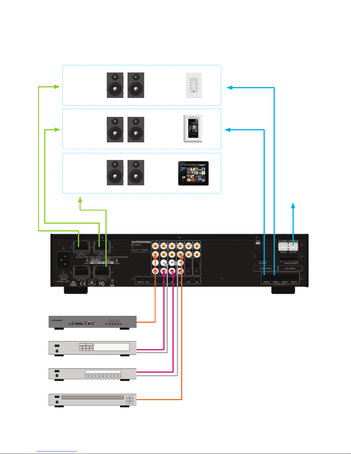
Typical System Conguration
FIGURE 1
Mirage Media Server
Satellite Receiver
Tuner
CD Player
Zone 1
Gym
KP-6
KP-iOS
Tablet
Zone 2
Study
Zone 3
Lounge
To Ethernet Router

9
Typical System Conguration (Continued)
Fig. 1 depicts a typical conguration where
the M-401e amplier is providing audio
into six of the possible eight listening zones.
Only three of the zones are depicted.
Each zone consists of a room with
a pair of speakers and a suitable
controller. Each zone may be listening
on any of the connected sources:
• Mirage Media Server
• Satellite Receiver
• Tuner
• CD Player
Controllers
Each zone has a specic control
requirement. Choose controllers
that best suit the application.
Zone 1 – The Gym: Speakers & KP-6 Keypad
Zone 2 – The Study: Speakers &
KP-iOS Keypad
Zone 3 – The Lounge: Speakers & Tablets
1. The KP-6 Keypad may be plugged into
any of the four controller ports.
2. Source control IR emitters are plugged
into the IR ports. There are ten IR ports:
IR1 - IR8, and IR9 & IR10.
3. IR 1 – 6 route source specific IR signals
from connected controllers, while IR9 &
IR10 output the common IR or the sum
of all received IR signals.
4. These ports may be used for source
equipment that is common to all zones.
When controlling a stand alone M-401e
using an iPad or other web tablet, the
M-401e must be connected to a wi-
enabled ethernet router and the web tablet
browser must be directed to the M-401e’s
IP Address. The M-401e’s web application
also provides source control functionality.
Speakers
Speakers in each zone are connected to the
amplier by "Home Run" speaker cables.
Source Equipment
The M-401e amplier has eight stereo
RCA audio inputs for connecting
to source equipment. These input
channels feature coax digital inputs.
If a signal is present on the digital input,
it takes precedence over the analog
input. There are four additional Digital
only input channels featuring both coax
and Optical inputs. Any source can be
listened to in any zone, simultaneously.
All eight zones may select the same
source, in such circumstances there
is a possibility that all four zones may
be trying to control that source (not
always desirable) so a system should be
well planned and where appropriate
additional source equipment installed.
Mirage Media Server
When pairing your M-401e amplier with
a Mirage Media Server, be sure to use the
Mirage Media Server’s web conguration
Sources page and follow the pairing process
there. This will ensure full control via the
Mirage iOS and Android applications.

Multiple Amplier Stacks
Mirage Media Server
Satellite Receiver
Tuner
CD Player
To Ethernet Router*
Linking to the Next M-401e or M-801e Multi-Zone Amplier
10
FIGURE 2

11
FIGURE 3
Controller Wiring
The M-401e is packed with control options:
• USB:
Used for firmware update.
• ETHERNET:
Two 100BaseT connections to a home network or to daisy chain other amplifiers.
• CONTROLLERS:
Conveys +12VDC, IR and data between the M-401e and KP-6 keypad controllers,
connected using CAT5 cables.
• BUS RUN:
For future use.
• TRIGGERS:
+12VDC 100mA trigger output when a zone is on.
Ethernet Protocol
The Ethernet port provides data acquisition and control of the Mirage ampliers by a home
automation system, or PC Via TCP port 17037.
Command Structure: <command> <zone> <data> <line feed>
Please see online support documents under the ampliers section.
Command Description
01 Standby
02 Mute
03 Source Selection
04 Volume
05 Bass
06 Treble
07 Balance
09 Send All parameters
0B Cause key press on Keypad
0C Amplier features
0D Maximum Volume Limit
11 Volume Up
12 Volume Down
14 Request Device information
1C Zone Name
1D Preamplier Volume Mode
26 Volume BCD format
Multiple Amplier (Continued)
In large installations where multiple M-401e
ampliers are required, Ethernet conveys
amplier control, and link to other Media
sources if connected to the Home network
Router or Switch. Ensure all ampliers
using same the amp ID in the stack.
The source equipment audio inputs must
be plugged into the rst amplier where
they are buffered and sent to the next
amplier in the stack. The maximum
recommended expansion is 24 units.
Zone
Ampliers are encoded with up to 96 zones.
The zone byte is used for checking if the
command is applicable to the device receiving
the command and if so, for optionally selecting
a sub-device, e.g. a bank or part of a device.
All Zones are addressed using FF. The lower 5
bits of the zone byte represent the zone 0 – 31.
Selection:
• 00000 bin = 00 (hex) = zone 0
• 00001 bin = 01 (hex) = zone 1
• 01010 bin = 0A (hex) = zone 10
• 11111 bin = 1F (hex) = zone 31
Examples:
Addressing a zone 10 amplier:
Binary 000-01010 or 0A hex
Send ASCII "0A"
Addressing all Zone amp & preampliers:
FF hex Send ASCII "FF"
*Fig 2 shows a stack of M-401e with Source
connections to rst amplier where they are
converted to Digital audio, buffered and sent
to the next amplier in the stack. Use good
quality Coax Digital Shielded RCA cables for
the interconnection, cables should be no
more than 3 meters or 10 feet. The maximum
recommended expansion is twelve units. This
chaining of Ethernet is an option but a direct
connection to the router is the best option.

12
Data
Command Content
Standby
(01)
00 – Standby OFF
01 – Standby ON
04 – Toggle
Mute
(02)
00 – Mute
01 – Un-mute
02 – Toggle Mute
Source Selection
(03)
00 – S5
01 – S6
02 – S7
03 – S4
04 – S8
05 – S1
06 – S2
07 – S3
Volume
(04) 00 – A0 range
Bass
(05) F4 – 0C (-12db - +12db)
Treble
(06) F4 – 0C (-12db - +12db)
Balance
(07) EC – 14 (Left –20db – Right –20db)
Send all parameters
(09) XX – value ignored
Amplier features
(0C)
00 – Loudness Disabled
01 – Loudness Enabled
Maximum Volume Limit (0D) 00 – A0 Range
Volume Up
(11) XX – Value Ignored
Volume Down
(12) XX – Value Ignored
Zone Name
(1C) Data eld contains the ASCII string.
Preamplier Volume Mode
(1D)
00 – A0 Range
FF = Independent Mode

13
Specications
A digital copy of this manual can be found at:
http://www.autonomic-controls.com/documents/Ampliers/Manual_Instructions_Mirage_401e.pdf
Notes
• When a command is sent to an amplifier
it will first be transmitted on the control
bus and then returned to the PC (Home
Automation System). If an error occurs an
error will be returned instead of the origi-
nal command. The PC (Home Automation
System) needs to ignore its command
when it is returned.
• A Standby ON command implies that the
amplifier is not muted, if the amplifier
was previously Off, a mute command
must follow the Standby command if it is
muted.
• Not all Command and Data commands
are covered in this document.
• The expected reply for the "Send all
Parameters" command (09) is >144 bytes.
All command fields listed in this document
are contained in the reply. The reply also
contains advanced commands not listed
in this document. The home Automation
or PC’s buffer should be large enough to
receive and process the 144-byte reply.
a. Zone 2 links to Zone 3.
b. Since Zone 2 is no longer linked to
Zone 1, Zone 1 will no longer be
linked to Zone 2.
c. Since Zone 3 is no longer linked to
zone 4, Zone 4 will no longer be
linked to Zone 3.
Example strings:
• 010A01: Standby ON command for Zone
10 amplifier.
• 012A01: Standby ON command for Zone
10 preamplifier.
• 060002: +2db Treble setting on Zone 0.
• 03IF02: Select Source 7 on Zone 31.
M·401e
Rated Output Power (FTC)
All Channels
55W per channel / 8Ω loads
75W per channel / 4Ω loads
Total Harmonic
Distortion (THD) 0.1% (50 Watt, 8 Ω load)
Damping Factor (8Ω load) 10
Speaker Impedance
(Z1 - Z6 L/R) 4Ω–8Ω
Analog Input Sensitivity
(S1 - S8 L/R) 0.75V RMS (Vol 100, Gain 0dB, 55W Output)
Analog Input Impedance
(S1 - S8 L/R) 22KΩ
Digital Input sensitivity 0dBFS
Frequency Response 48 KHz sample rate: 10Hz - 22 KHz
96 KHz sample rate: 10Hz - 42 KHz
Tone Control ±12dB, 100Hz (Bass)
±12dB, 10kHz (Treble)
Signal to Noise Ratio 95dB (IHA-A, 0.75V input / unbalanced)
IR Output (6) 3.5mm Jack: IR1 - IR8 current limited to 25mA
Source Inputs (6) Digital Coaxial RCA, (4) Analog (L/R) RCA, (2) TOSLINK
Ethernet (2) 100Base-T, MAIN IN and Switch EXT OUT
USB (1) USB mini-B female 5 pin
Data (1) 4 pole 3.5 mm terminal block connector (Data,12V, IR,0V)
Controllers (4) RJ45 sockets Keypad controller ports
BUS RUN (1) 4 way terminal block (0V, IR 12V & Data)
Amp On & PG Control (1) 8 way terminal plug with Amp ON 1 - 8 and (2) page preset contact
closure inputs: PG1 & PG2
Zone Triggers & Presets (1) 8 pole 3.5 mm terminal block connector
(Zone trigger 0V out, Zone trigger 1 - 8 12V out, Common, Preset 1 - 2 in)
Power Supply 110–240V AC 50–60Hz
Power Consumption 650W
Standby Power Consumption 6W
Dimensions with feet 4.0" H x 17" W x 15" D (10.2cm x 43.2cm x 38.1cm)
Weight 15.4 lb. (7 kg)
Height including feet 105 mm
Zones (4) zones
Expandable to 96 zones, attaching additional M-401e or M-401e ampliers
©2006–2016 Autonomic Controls, Inc.. Autonomic, eAudioCast, and TuneBridge are registered trademarks of Autonomic Controls, Inc.
All other trademarks are property of their respective owners. Specications are based on current revision and may change without notice. 121216
Acknowledgments – FreeRTOS – uIP
The M-401e rmware is based in part on FreeRTOS.org™V5.0.2 and the uIP TCP/IP stack. For more information on FreeRTOS.org™please visit http://www.freertos.org. Source code for FreeRTOS.org™ can be
downloaded from their ofcial website. The following copyright and statements for uIP TCP/IP stack are required by license: Copyright © 2001-2003, Adam Dunkels. All rights reserved.
1. Redistribution and use in source & binary forms, with or without modication, are permitted provided that the following conditions are met.
2. Redistributions of source code must retain the above copyright notice, this list of conditions and the following disclaimer.
3. Redistributions in binary form must reproduce the above copyright notice, this list of conditions and the following disclaimer in the documentation and/or other materials provided with the distribution.
The name of the author may not be used to endorse or promote products derived from this software without specic prior written permission.
THIS SOFTWARE IS PROVIDED BY THE AUTHOR "AS IS" AND ANY EXPRESS OR IMPLIED WARRANTIES, INCLUDING, BUT NOT LIMITED TO, THE IMPLIED WARRANTIES OF MERCHANTABILITY AND FITNESS FOR A
PARTICULAR PURPOSE ARE DISCLAIMED. IN NO EVENT SHALL THE AUTHOR BE LIABLE FOR ANY DIRECT, INDIRECT, INCIDENTAL, SPECIAL, EXEMPLARY, OR CONSEQUENTIAL DAMAGES (INCLUDING, BUT NOT LIMITED
TO, PROCUREMENT OF SUBSTITUTE GOODS
Table of contents
Other Autonomic Amplifier manuals


