AUTROFIELDBUS Protocol Converter, BSD-321/EX
Autronica Fire and Security AS
Fire and Security, Trondheim, Norway. Phone: + 47 73 58 25 00, fax: + 47 73 58 25 01
Oil & Gas, Stavanger, Norway. Phone: + 47 51 84 09 00, fax: + 47 51 84 09 99
Maritime Sales, Spikkestad, Norway. Phone: + 47 31 29 55 00, fax: + 47 31 29 55 01
Visit Autronica Fire and Security’s website: www.autronicafire.com
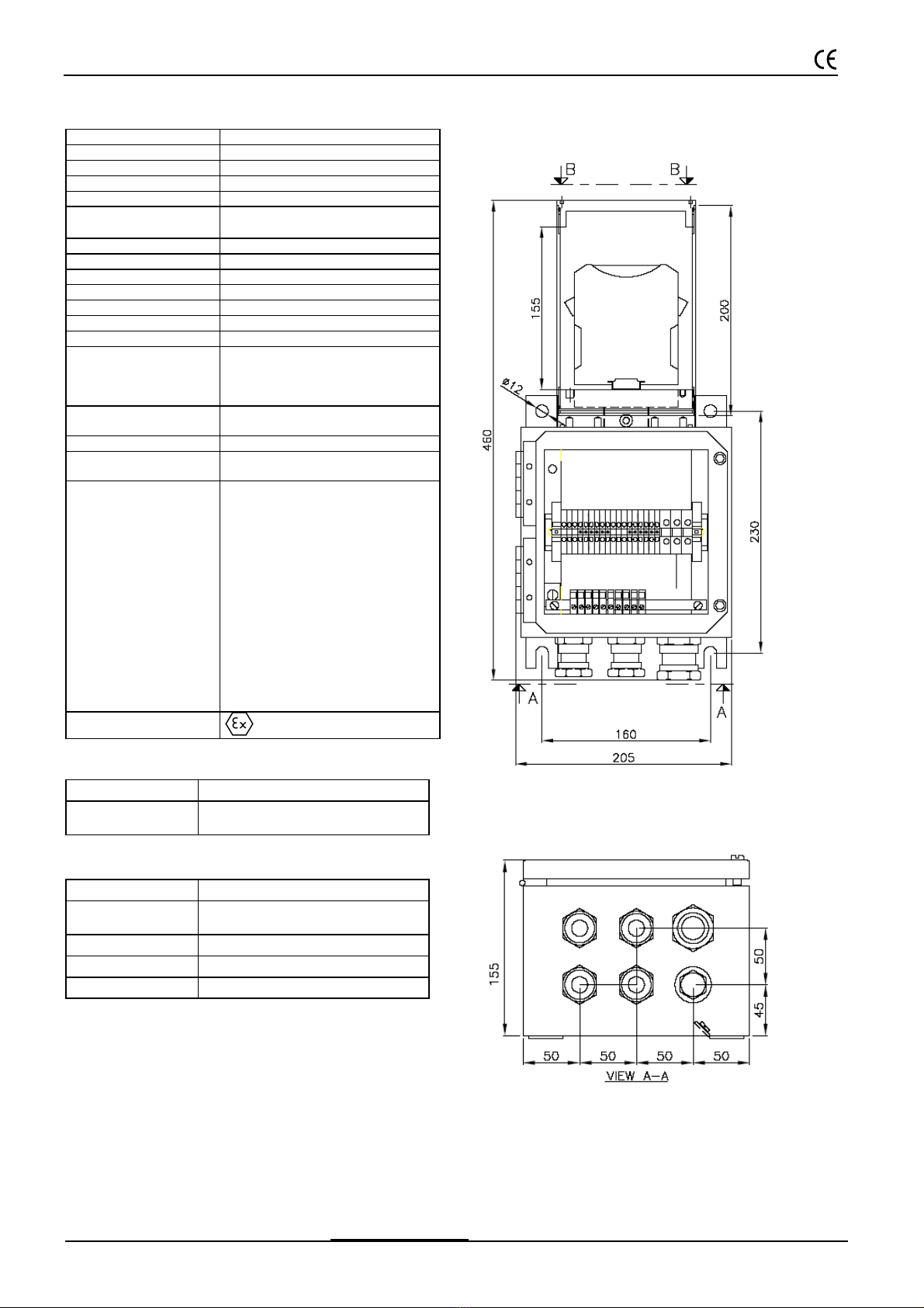
The BSD-321 is intended for use with 24VDC power
supplies. It may be used in single or dual earth sys-
tems.
19
20
21
BSD-321/Ex
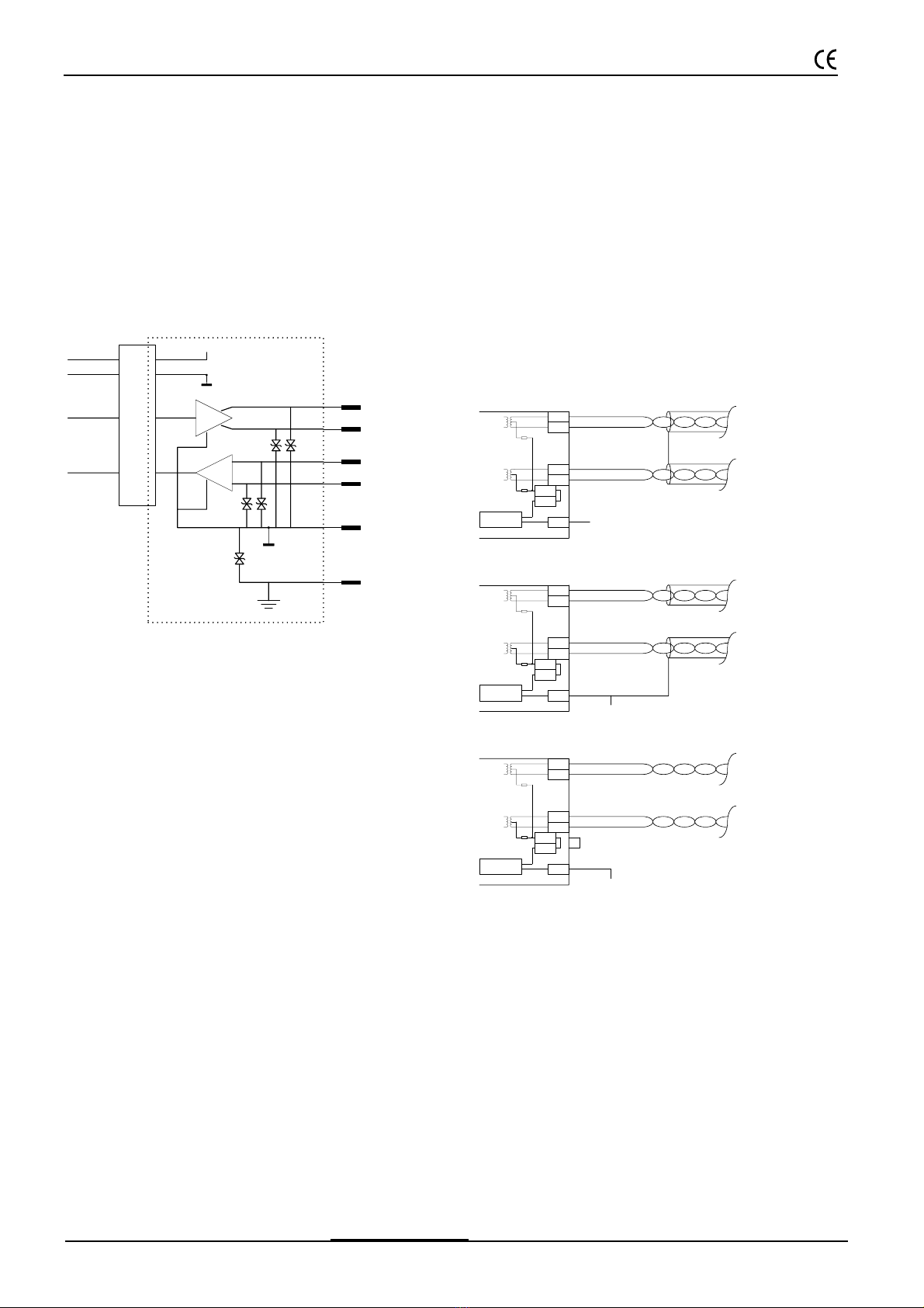
+24V
0V
DC power supply
+24 in
0V in
IE
PE-bar
BSD-321/Ex power,
Single earth system
19
20
21
BSD-321/Ex
+24V
0V
DC power supply
+24 in
0V in
IE
PE-bar
BSD-321/Ex power,
Dual earth system
System IE
System PE
For further earth & shielding information reference
to the System Description AutroSafe IFG.
Order number: 116-P-ASAFE-IFG/XE.
RS-485 Detector interface with loop-back
4
6
8
13
15
17
AA
BB
A
B
ref
BSD-321/Ex detector
AA
BB
A
B
ref
BSD-321/Ex detector
A
B
RS-485 cable shielding
RS-485 cable shielding
RS-485 earth
fault sensor
RS-485 earth
fault sensor
RS-485 branch connection (local loop-back):
RS-485 loop connection (remote loop-back):
Port 0
Port 1
Port 0
Port 1 4
8
13
15
17
6
Loop-back of RS-485 can be done either locally on
BSD-321 or remotely with loop to/from detector.
The BSD-321 requires a RS-485 loop-back connec-
tion. Loop-back is used to give increased system
safety. The extra port verifies the communication
path. This also opens the option to using RS-485
loop connection for dual communication paths to the
detectors.
Loop-back for optimum safety is required for SIL2
applications (To be approved).
Switches S1 and S2 must be set accordingly for
correct termination.
Local loop-back:
• Set S2-6 OFF (Disable EOL resistor for port 1)
• The detector at the other end of the RS-485 bus
must enable its EOL resistor
Remote loop-back:
• Set S2-6 ON (Enable EOL resistor for port 1)
• None of the detectors must have EOL resistors
Earth fault detection on the RS-485 bus
Earth fault detection is enabled on the RS-485 link
by when S2-2 is ON. The monitoring circuit monitors
unintended connection between the A+ wire (inter-
nal connector 17) and the port 0 ref wire (connector
28), or between the B- wire (internal connector 18)
and the port 0 ref wire (internal connector 28).
The ”ref” signal on the detector
The ref signal on the detector is the detectors
”common” signal for the RS-485. This signal may be
connected to IE (or earth in single earth systems),
to the detectors power supply 0V or it may be iso-
lated (floating).