Autronica BS-200 User guide

Interactive Fire Detection System
System Description
Protecting life, environment and property...
116-APRIME-SYSTEMD/XGB 2007-10-10

COPYRIGHT ©
This publication, or parts thereof, may not
be reproduced in any form, by any
method, for any purpose.
Autronica Fire and Security AS and its
subsidaries assume no responsibility for
any errors that may appear in the
publication, or for damages arising from
the information in it. No information in this
publication should be regarded as a
warranty made by Autronica Fire and
Security. The information in this
publication may be updated without
notice.
Product names mentioned in this
publication may be trademarks. They are
used only for identification.

Table of Contents
System Description, Autroprime Interactive Fire Detection System, 116-P-APRIME-SYSTEMD/XGB 2007-10-10,
Autronica Fire and Security AS
Page 1
Table of Contents
1. Introduction.......................................................................3
1.1 About the Handbook .........................................................................3
1.2 The Reader .......................................................................................3
1.3 Reference Documentation ................................................................3
2. System Characteristics....................................................4
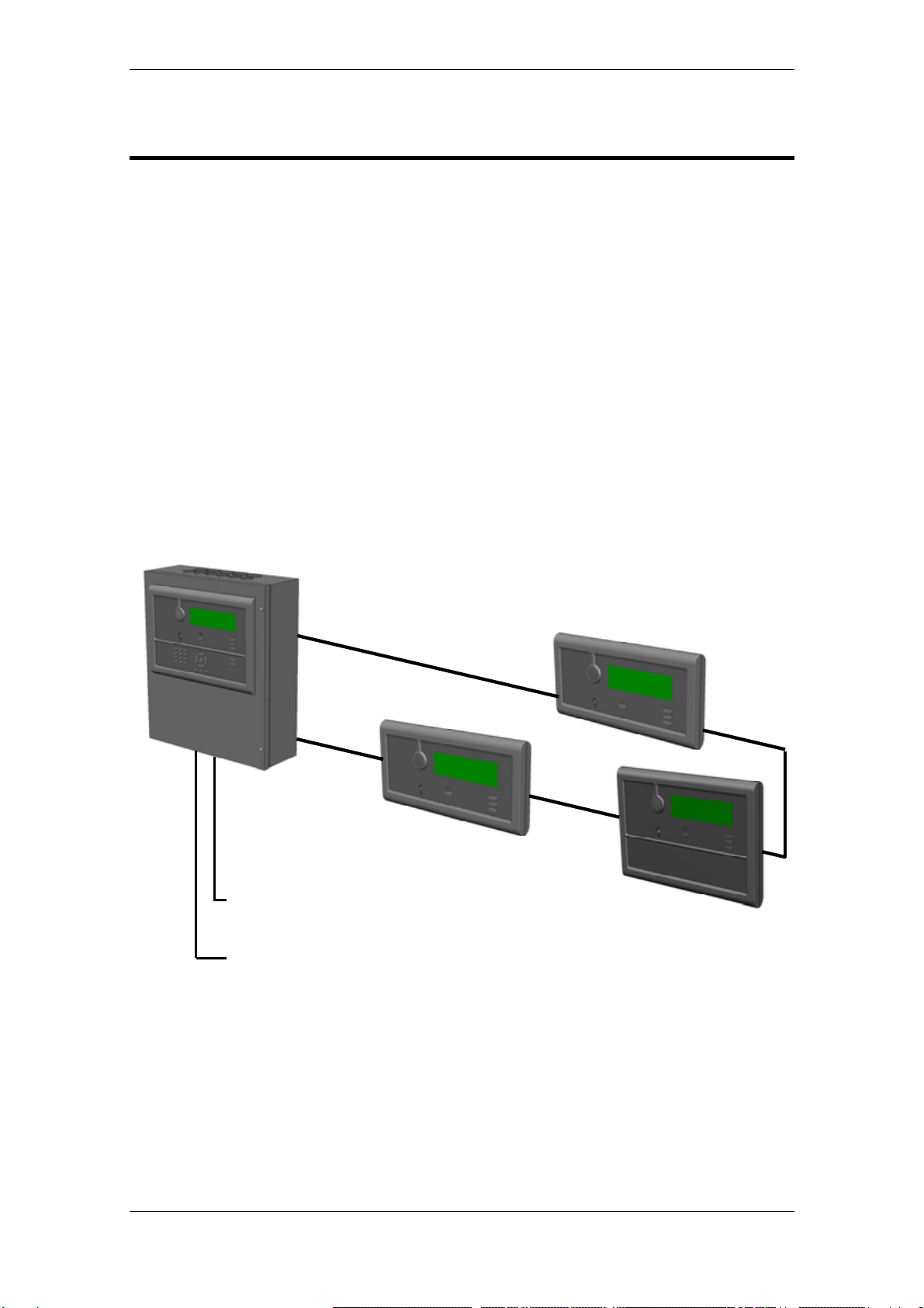
2.1 System Overview ..............................................................................4
2.2 Applications.......................................................................................5
2.3 System Functionality.........................................................................5
2.4 Compliance with Regulations and Standards...................................6
2.5 EN 54-2 Functionality List .................................................................6
2.5.1 Optional functions with requirements of this European
Standard..................................................................................6
2.5.2 Functions relating to other parts of EN 54..............................7
2.5.3 Ancillary functions not required by this European
Standard..................................................................................7
2.6 CE Marking Information ....................................................................8
2.7 Definitions..........................................................................................8
2.8 System Capacity ...............................................................................8
2.9 Detection Loops ................................................................................9
2.10 Zoning Concept.................................................................................9
2.10.1General ...................................................................................9
2.10.2Detection Zone........................................................................9
2.10.3Alarm Zone..............................................................................9
2.10.4Parent Alarm Zone..................................................................10
2.11 Configuration / Service......................................................................10
2.11.1Ready-to-use in a Pre-configured State .................................10
2.11.2Site-specific configuration.......................................................10
2.11.3Downloading / Uploading........................................................11
2.11.4Service ....................................................................................11
2.12 Communication Ports........................................................................11
2.13 Interfacing Peripheral Equipment......................................................11
2.14 Language Options.............................................................................12
2.15 Power Supply....................................................................................12
2.16 Environmental Requirements............................................................12
2.17 SelfVerify™ Function.........................................................................13
2.18 Operation Classes for different Detection Methods..........................13
2.19 Performance Classes for Environmental Adaptivity..........................14
2.20 Interactive Detectors with Dynamic Filtering (DYFI+).......................15
2.21 Built-in Short-circuit Isolator..............................................................16

Table of Contents
System Description, Autroprime Interactive Fire Detection System, 116-P-APRIME-SYSTEMD/XGB 2007-10-10,
Autronica Fire and Security AS
Page 2
3. Panel Description .............................................................17
3.1 Fire Alarm Control Panels BS-200....................................................17
3.2 Operator Panel BS-210.....................................................................18
3.3 Repeater Panel BS-211 ....................................................................18
3.4 Fire Brigade Panel BU-210...............................................................19
3.5 Information Panel BV-210.................................................................19
3.6 Mimic Driver BUR-200 ......................................................................20
3.7 “Larmlagringspanel” BU-211.............................................................20
4. Panel Inputs and Outputs ................................................21
4.1.1 Main Terminal Block J1...........................................................21
4.1.2 Auxiliary Terminal Block J4.....................................................22
4.1.3 User Configurable Inputs........................................................22
4.1.4 User Configurable Outputs .....................................................22
5. Detectors and Loop Units................................................23
5.1 Overview ...........................................................................................23
5.1.1 Heat detectors.........................................................................23
5.1.2 Smoke detectors.....................................................................23
5.1.3 MultiSensors ...........................................................................23
5.1.4 Manual Callpoints ...................................................................24
5.1.5 Special detector interface .......................................................24
5.1.6 Beam detectors.......................................................................24
5.1.7 Flame detectors ......................................................................24
5.1.8 Aspirating detectors................................................................24
5.1.9 Loop sounders (Fire Alarm Devices)......................................24
5.1.10Control and Interface units......................................................24
6. Reader’s Comments.........................................................25

Introduction
System Description, Autroprime Interactive Fire Detection System, 116-P-APRIME-SYSTEMD/XGB 2007-10-10,
Autronica Fire and Security AS
Page 3
1. Introduction
1.1 About the Handbook
This document provides a description of the Autroprime Interactive
Fire Detection System (hereby called Autroprime), a system for
small-to-medium-sized applications.
1.2 The Reader
This handbook is intended for consultants, sales personnel, potential
customers and distributors.
1.3 Reference Documentation
The table below shows an overview of the complete technical
documentation that is available in several languages on the
Autroprime Documentation CD-ROM delivered with the panel:
Documents on the Autroprime
Documentation CD-ROM Part number File name
System Description 116-P-APRIME-SYSTEMD/XGB aprimesystemd_xgb
Getting Started 116-P-APRIME-GESTART/EGB aprimegestart_egb
Installation Handbook 116-P-APRIME-INSTALL/DGB aprimeinstall_dgb
Connecting Loop Units 116-P-CONNECTLOOPUNIT/DGB connectloopunit_dgb
Configuration Handbook 116-P-APRIME-CONFIGU/EGB aprimeconfigu_egb
Operator’s Handbook 116-P-APRIME-OPERATE/FGB aprimeoperate_fgb
User Guide 116-P-APRIME-USERGUI/LGB aprimeusergui_lgb
Wall Chart 116-P-APRIME-WALLCHA/LGB aprimewallcha_lgb
Menu Structure 116-P-APRIME-MENUSTR/MGB aprimemenustr_mgb
Datasheet; Fire Alarm Control Panel BS-200 116-P-BS200/CGB bs200_cgb
Datasheet;
Fire Alarm Control Panel BS-200M 116-P-BS200M/CGB bs200m_cgb
Datasheet;
Fire Alarm Control Panel BS-200L 116-P-BS200L/CGB bs200l_cgb
Datasheet; Repeater Panel BS-211 116-P-BS211/CGB bs211_cgb
Datasheet; Information Panel BV-210 116-P-BV210/CGB bv210_cgb
Datasheet; Fire Brigade Panel BU-210 116-P-BU210/CGB bu210_cgb
Datasheet; Mimic Driver BUR-200 116-P-BUR200/CGB bur200_cgb

System Characteristics
System Description, Autroprime Interactive Fire Detection System, 116-P-APRIME-SYSTEMD/XGB 2007-10-10,
Autronica Fire and Security AS
Page 4
2. System Characteristics
2.1 System Overview
Autroprime is a stand-alone fire detection system.
The Fire Alarm Control Panel supports 2 detection loops (the maritime
variant supports 4 detection loops). All loop units can be mixed freely
and connected at any point on the same detection loop.
A maximum of 8 additional panels can be freely mixed and connected
to the Fire Alarm Control Panel via the RS-485 panel bus, including
Repeater Panels BS-211, Information Panels BV-210,
Fire Brigade Panels BU-210 and Mimic Drivers BUR-200.
For information on system capacity, refer to chapter 2.8.
Fire Alarm Control Panel BS-200
ESPA 444 Communication Protocol or
NMEA protocol for VDR systems (RS-232, RS-422/485)
Modbus RTU protocol (serial/ethernet)
RS-485 Panel bus BU-210
BS-211
BV-210

System Characteristics
System Description, Autroprime Interactive Fire Detection System, 116-P-APRIME-SYSTEMD/XGB 2007-10-10,
Autronica Fire and Security AS
Page 5
2.2 Applications
Autroprime covers a large range of applications; the panels are
available in three variants intended for use in land applications,
agricultural and horticultural applications as well as maritime
applications (refer to Panel Description, chapter 3).
Among several land applications, Autroprime is especially suitable
for
• day-care centres, health care institutions
• schools
• overnight stops, motels
• stores
• official buildings
• churches
• industrial and commercial buildings
• museums, art galleries, libraries, archives
• conference centres
• data centres
Agricultural and horticultural applications cover, among others:
• farm buildings
• store houses
• outbuildings
• market gardens
• hay barns
• grain silos
• stables, stud farms
• abbatoirs
Maritime applications cover, among others:
• smaller cargo boats
• fishing boats
• work boats
• ferries
• yachts
2.3 System Functionality
Autroprime provides both basic and advanced functionality within fire
detection for a wide range of applications (refer to chapter 2.2). The
system is developed for worldwide standards and regulations.
The system provides simple configuration, installation, operation and
service routines.
For detailed information on the system functionality and how to
operate the system, refer to the Operator’s Handbook.

System Characteristics
System Description, Autroprime Interactive Fire Detection System, 116-P-APRIME-SYSTEMD/XGB 2007-10-10,
Autronica Fire and Security AS
Page 6
2.4 Compliance with Regulations and Standards
Autroprime complies with C.E.N. EN 54 regulations, FM regulations
(Factory Mutual) and the maritime SOLAS requirements (Safety Of
Life At Sea).
2.5 EN 54-2 Functionality List
With reference to 12.2.1 in EN 54-2.
h) a general description of the equipment, including a list of the:
• optional functions with requirements of this European Standard
(chapter 2.5.1 in this handbook)
• functions relating to other parts of EN 54 (chapter 2.5.2 in this
handbook)
• ancillary functions not required by this European Standard (chapter
2.5.3 in this handbook)
2.5.1 Optional functions with requirements of this European Standard
EN 54-2
Clause Imple-
mented Option text Description/Requirement Autroprime functionality
7.8 Yes Output to Fire
Alarm
Device(s)
Automatic transmission of fire
alarm signals to fire alarm
devices.
7.9 Yes Output to Fire
Alarm
Routing
Equipment
Automatic transmission of fire
alarm signals to fire alarm
routing equipment.
Indicated by separate light
emitting indicator.
7.10 Yes Output to Fire
Protection
Equipment
Transmission of fire alarm
signals to controls for automatic
fire protection equipment.
Output type A
7.11 Yes Delays to
outputs Delay the actioning of outputs to
fire alarm devices and/or fire
alarm routing equipment.
Prepared through
configuration.
Entering Day-mode (input
or menu) activates delays.
Manual call points may
override delays.
7.12 Yes Dependency
(Type C) Inhibit either the indication fire
alarm condition, or the operation
of outputs, until confirmatory
signals are received.
Detection zone configured
as ‘Dependency’.
Panels will indicate fire
alarm condition. Outputs
inhibited until confirmatory
signals. Manual call points
overrides co-incidence.
7.13 No Alarm
counter Record the number of instances
that the c.i.e. enters the fire
alarm condition.
Search ‘filters’ in Log may
give alarms or resets only
(with date/time).
8.3 Yes Fault signal
from points Faults shall be indicated at least
as zone faults. Interpreted to be better to
give detailed point info.
8.4 No Total loss of
power supply An indication shall be given for a
period of at least one hour.
8.9 Yes Output to
Fault
Warning
Routing
Equipment
Transmission of fault signals to
fault warning routing equipment.
9.5 Yes Disablement
of
addressable
points
Disabling and enabling points
individually, or in groups, by
manual operation.
If all points within a
detection zone are
disabled, the indication
changes to zone
disablement.

System Characteristics
System Description, Autroprime Interactive Fire Detection System, 116-P-APRIME-SYSTEMD/XGB 2007-10-10,
Autronica Fire and Security AS
Page 7
EN 54-2
Clause Imple-
mented Option text Description/Requirement Autroprime functionality
10 Yes Test
condition Testing the processing and
indication of fire alarm signals
from zones.
11 No Standardized
input/output
interface
Standardized input/output
interface, suitable for the
transmission and reception of
signals to and from ancillary
equipment.
Communication options
available. Serial line
protocol to cover required
functionality in 11a) and
11b) to be defined. See
also ancillary function list.
12.5 Yes Integrity of
transmission
paths
12.5.3 and 12.5.4. c.i.e. in more
than one cabinet. Operator panel may be
separated from the main
cabinet, additional operator
panels on a panel bus.
2.5.2 Functions relating to other parts of EN 54
EN 54 part no Description
EN 54-4 Power supply equipment Battery internal resistance and deep discharge.
2.5.3 Ancillary functions not required by this European Standard
Ancillary function Description
Supervisory condition Condition for monitoring ancillary equipment related to life, safety
or property protection.
Pre Alarm condition A warning level from the detectors with zone indication on display.
Point info. available. Implemented as a condition in line with those
required by the standard.
Self Verifying Function An automatic, calibrated test of all detectors, interfaces,
connections and cables for 300- and 500-series equipment. Series
200 without SV.
DYFI+ Dynamic Filtering, introduced in our BS-100 c.i.e., further
enhanced in AutroSafe and Autroprime.
Environmental Adaptivity Autroprime detectors may be programmed for environments,
clean, normal, industrial.
SOLAS functionality Mandatory functional requirements given by Safety Of Life At Sea
(SOLAS) for installations on ships.
Dependency on more than one
alarm signal As defined in proposal for new EN 54-2 (Type C dependency).
Repeater panels Alarm indication and silence/reset buttons.
(In accordance with Annex G, an ancillary function without
requirements. See also above option: 11 Standardised
input/output interface)
Information panel Event indication only. (Comment as for Repeater panel).
Loop units short circuit isolators Communication path between neighbouring loop units may be
isolated in case of short circuit or break. Provided connection as a
loop (recommended), no loop units will be lost in case of such a
fault.
Alarm zones Means of sub-dividing the alarming area in an installation during
fire alarm condition

System Characteristics
System Description, Autroprime Interactive Fire Detection System, 116-P-APRIME-SYSTEMD/XGB 2007-10-10,
Autronica Fire and Security AS
Page 8
2.6 CE Marking Information
2.7 Definitions
• A System Unit is defined as a unit that is directly connected to the
Fire Alarm Control Panel’s internal bus system.
• A Loop Unit is defined as either a Point, an I/O-unit or an Electronic
Sounder that is connected to a detection loop.
• A Point is defined as either a detector or a manual call point.
2.8 System Capacity
Maximum number of;
Detection Loops per fire alarm control panel, standard and agricultural variant 2
Detection Loops per fire alarm control panel, maritime variant 4
Loop units per detection loop 127
Loop units per branch on a detection loop 32
Loop sounders per detection loop 40
Fire Brigade/Information/Repeater panels per fire alarm control panel 8
Serial ports 1
Ethernet 1
USB Host ports 2
Mimic Driver BUR-200 1
Languages supported 15
Autronica Fire and Security AS
7483 Trondheim
07
EN 54 –2:2007
Control and indicating equipment for fire detection and fire alarm systems for
buildings
BS-200 / BS-200M / BS-200L
Provided options:
See chapter 2.5.1 in this handbook.
Other technical data:
See
Autroprime Installation Handbook 116-P-APRIME-INSTALL/DGB

System Characteristics
System Description, Autroprime Interactive Fire Detection System, 116-P-APRIME-SYSTEMD/XGB 2007-10-10,
Autronica Fire and Security AS
Page 9
2.9 Detection Loops
Autroprime uses the Al_Com Loop Technology (used in the
AutroSafe system) for the communication with detection loops.
• The maximum number of detection loops are 2 for land variants
(standard panel and panel for agrilcultural applications) and 4 for
the maritime variant.
• The panel supports branch-offs on the loop. If necessary, a branch-
off can be connected to a detection loop if the existing cable layout
requires this. The maximum number of loop units on a branch is 32.
2.10 Zoning Concept
2.10.1 General
The term “zone” describes the zonal concept of the system. Assigning
system components to zones enables control from detection to
activation of alarm. The following zones apply:
• Detection Zone (DZ)
• Alarm Zone (AZ)
• Neighbour Alarm Zone
2.10.2 Detection Zone
A Detection Zone (DZ) is defined as a zone with one or more points
(detectors or manual callpoints) that logically belong together,
determined by geographical/functional parameters (for example, the
sales department on the second floor).
A point can only be assigned to one Detection Zone, and can only
refer to one specific location in the system (for example, a specific
office on the second floor in a building).
The Detection Zone will be the trigger to generate outputs to the
Alarm Zone.
2.10.3 Alarm Zone
An Alarm Zone (AZ) is activated by one or several Detection Zones.
Example:
An alarm from one of the devices in DZ3 will activate Fire Alarm
Devices in AZ1.
Within the same alarm zone, alarm sounders give the same audible
signal.

System Characteristics
System Description, Autroprime Interactive Fire Detection System, 116-P-APRIME-SYSTEMD/XGB 2007-10-10,
Autronica Fire and Security AS
Page 10
2.10.4 Parent Alarm Zone
The top-level Alarm Zone is called the Parent Alarm Zone. A system
can consist of a Parent Alarm Zone with several “sub-level” alarm
zones in an hierarchy. Each “sub-level” alarm zone is related to a
specific area of, for example, a building. If an alarm occurs in a Parent
Alarm Zone, all Fire Alarm Devices (FADs) within the Parent Alarm
Zone, plus all FADs belonging to all “sub-level” alarm zones will be
activated.
2.10.4.1 Neighbour Alarm Zone
Geographically associated alarm zones can be defined as neighbour
alarm zones, such that these can operate outputs for alarm zones
adjacent to the incident.
Defining neighbour zones allows the fire alarm control panel to
activate the sounders in alarm zones that are neighbours. This means
that areas that are adjacent to each other – and may therefore be at
risk – are warned in the event of a fire alarm.
2.11 Configuration / Service
2.11.1 Ready-to-use in a Pre-configured State
Autroprime is provided to the user in a pre-configured state, in this
state the panel is set to recognize detectors and other loop units
connected to the detection loops and the availability of routing
equipment, etc. As such, the system is fully functional and ready-to-
use simply by turning ON the power, but not configured to respond in
any non-default way. A functional verification of the panel is run to
assure the panel itself is fully functional.
2.11.2 Site-specific configuration
Basic site-specific configuration can be performed by means of the
panel buttons (access level 3/service), typically including:
• naming and assigning detectors to Detection Zones
• naming and defining the number and type of Detection Zones
(Immediate Action, Dependency Action, Delayed Action, Delayed
Dependency Action, SOLAS)
• assigning Fire Alarm Devices to Alarm Zones
• specifying the Detections Zones that can activate selected Alarm
Zones
• configuring “conditions” for outputs, for example, dependency
action; meaning that at least two detectors in the same detection
zone must be in alarm state before actions are initiated
• assigning Detection Zones to Disable devices (BW-200)

System Characteristics
System Description, Autroprime Interactive Fire Detection System, 116-P-APRIME-SYSTEMD/XGB 2007-10-10,
Autronica Fire and Security AS
Page 11
2.11.3 Downloading / Uploading
Configuration data can be downloaded or uploaded by connecting a
memory stick to one of the two USB outputs, easily accessible from
the inside of the front panel door. The maximum load on each USB
output is 100mA. Each USB port is provided with a resettable fuse.
2.11.4 Service
Autroprime provides readout of the loop topology (Loop Sequence
Indexes) and loop unit ID-numbers.
The system generates reports providing the detection loop status at
selected service intervals.
2.12 Communication Ports
• A serial bus communication is used for the communication between
the Autroprime Fire Alarm Control Panel, Repeater panels, Fire
Brigade panels and Information panels.
• The system offers 1 serial port for communication with third-party
equipment via RS-232, RS-422 or RS-485. The baud rate is
selectable.
2.13 Interfacing Peripheral Equipment
For communication with peripheral equipment / third-party equipment
the following protocols are used:
• ESPA 4.4.4, allowing connectivity with devices such as AutroTel
alarm routing via telephone networks and pocket paging systems.
• NMEA-0183, allowing connectivity with devices such as the
maritime Voyage Data Recorder (VDR).
• MODBUS, allowing connectivity with Programmable Logic
Controllers (PLC).

System Characteristics
System Description, Autroprime Interactive Fire Detection System, 116-P-APRIME-SYSTEMD/XGB 2007-10-10,
Autronica Fire and Security AS
Page 12
2.14 Language Options
Autroprime supports the following languages (listed in alphabetical
order):
• Danish
• Dutch
• English
• Finnish
• French
• German
• Hungarian
• Icelandic
• Italian
• Norwegian
• Polish
• Portuguese (Brazilian)
• Russian
• Spanish
• Swedish
2.15 Power Supply
Autroprime features an integrated power supply SC-150-27MB.
Mains monitoring:
If the mains power is lost, fault messages may be delayed 1-60
minutes (configurable).
The panel can be powered from a fixed 24VDC source.
2.16 Environmental Requirements
The equipment complies with environmental conditions of IEC-721-3-
3 class 3k5.
Ambient temperature:-5 to +55 C
Degree of protection:
• BS-200 and BS-200L: IEC-529/IP30
• BS-200M: IEC-529/IP32

System Characteristics
System Description, Autroprime Interactive Fire Detection System, 116-P-APRIME-SYSTEMD/XGB 2007-10-10,
Autronica Fire and Security AS
Page 13
2.17 SelfVerify™Function
Autroprime features the SelfVerify™ function which makes the
system capable of inspecting and verifying itself every day. Every day
the system completely checks all detectors, interfaces, connections
and cables - from detector chamber through to the alarm output.
2.18 Operation Classes for different Detection Methods
The MultiSensor detector can be manually set to three different
Operation Classes, allowing you to choose the MultiSensor’s
detection method and calculation. The Operation Classes are as
follows;
• MultiSensor (optical detection with heat enhancement)
• Heat only (thermal detection only) - class A1
• MultiSensor with Heat (a combination of optical detection with heat
enhancement and Heat class A1)

System Characteristics
System Description, Autroprime Interactive Fire Detection System, 116-P-APRIME-SYSTEMD/XGB 2007-10-10,
Autronica Fire and Security AS
Page 14
2.19 Performance Classes for Environmental Adaptivity
Autroprime uses detectors that can be programmed to one of three
different Performance Classes, with sensitivity settings covering the
following environments:
• clean environments, for example laboratories, data rooms etc.
• normal environments, for example offices and hospitals etc.
• industrial environments, for example, factories and warehouses etc.
By choosing a sensitivity setting that suits the environment, it is
possible to achieve an accurate and reliable system, providing the
optimal detection, whilst virtually eliminating false alarms.
All three different sensitivity settings comply with the C.E.N.
regulations EN-54.

System Characteristics
System Description, Autroprime Interactive Fire Detection System, 116-P-APRIME-SYSTEMD/XGB 2007-10-10,
Autronica Fire and Security AS
Page 15
2.20 Interactive Detectors with Dynamic Filtering
(DYFI+)
Autroprime features detectors with the digital filter technology DYFI+.
False alarms are virtually eliminated, and the system provides the
earliest possible warning of a potential fire - before it becomes a
problem.
The DYFI+ digital filtering is present in each detector. Each detector
has three different filter functions:
The smouldering fire filter provides
accurate and quick detection in the event
of a smouldering fire, i.e. in a situation
where a potential fire with no flames
develops during a longer period.
The transient filter virtually eliminates false
alarms caused by phenomena that are not
related to a real fire. Such phenomena can be
short pulses caused by, for example, vapour,
cigarette smoke etc.
The pollution filter maintains the chosen
sensitivity throughout the detector’s entire
lifetime, even with a polluted detector..

System Characteristics
System Description, Autroprime Interactive Fire Detection System, 116-P-APRIME-SYSTEMD/XGB 2007-10-10,
Autronica Fire and Security AS
Page 16
2.21 Built-in Short-circuit Isolator
The loop resistance on the detection loop is continously monitored to
register a possible break or short-circuit on the detection loop. Each
individual detector has a built-in short-circuit isolator.
In the event of a short-circuit in the detector cable, the short-circuit
location will be isolated as the short-circuit isolator will be activated in
the detectors on either side.

Panel Description
System Description, Autroprime Interactive Fire Detection System, 116-P-APRIME-SYSTEMD/XGB 2007-10-10,
Autronica Fire and Security AS
Page 17
3. Panel Description
3.1 Fire Alarm Control Panels BS-200
Autroprime fire alarm control panels are available in three variants
BS-200, BS-200L and BS-200M, these variants differ in the following
ways:
• BS-200; Standard panel for land applications
• BS-200L; Standard panel for agricultural and horticultural
applications (FG-approval for the Norwegian market)
• BS-200M; Standard panel for maritime applications
BS-200 panels all feature the same interface and appearance, but
differ slightly in capacity and whether or not they are
approved/certified for use in given applications.
The panel serves as a stand-alone operating panel, or as a master
panel in a networked system (on a RS-485 panel bus). All alarm
handling and system features can be configured, controlled and
monitored from the panel.
The Operator Panel (BS-210), which is an integrated part of the
BS-200 panel, can also be mounted separately outside the cabinet.
See separate datasheets for details of each variant.

Panel Description
System Description, Autroprime Interactive Fire Detection System, 116-P-APRIME-SYSTEMD/XGB 2007-10-10,
Autronica Fire and Security AS
Page 18
3.2 Operator Panel BS-210
The Autroprime Operator Panel BS-210 is delivered as an integrated
part of the Fire Alarm Control Panel but can also easily be removed
from the Fire Alarm Control Panel and mounted separately outside a
cabinet on a wall bracket.
3.3 Repeater Panel BS-211
The Autroprime Repeater Panel BS-211 is identical to the Operator
Panel BS-210, but has no alphanumeric keypad.
A maximum of 8 additional panels (including Repeater
Panels/Information Panels/Fire Brigade panels) can be connected to a
Fire Alarm Control Panel via the RS-485 panel bus.
All alarm handling and system events can be controlled and monitored
from the panel.
For detailed information, see separate datasheet.
Other manuals for BS-200
1
This manual suits for next models
2
Table of contents
Other Autronica Firefighting Equipment manuals
Popular Firefighting Equipment manuals by other brands

Cooper Lighting Solutions
Cooper Lighting Solutions 4125 Series instructions

MFA
MFA GORE WARNING & USER INFORMATION GUIDE

Task Force Tips
Task Force Tips Vortex 1.5" manual

Dräger
Dräger PSS Merlin System Instructions for use

Bentel Security
Bentel Security FireClass FC500-MFI installation manual

QTAC
QTAC 85 EMS owner's manual