Autronica 116-GR-7600/V2 User manual

Quick Installation Guide –116-GR-7600/V2 Wireless Emergency Lighting
[1]
WEL_qInstallGuide_V2_rv3 - Autronica.docx
116-GR-7600/V2
WIRELESS EMERGENCY LIGHTING
Quick Installation Guide

Quick Installation Guide –116-GR-7600/V2 Wireless Emergency Lighting
[2]
WEL_qInstallGuide_V2_rv3 - Autronica.docx
116-GR-7600/V2
WIRELESS EMERGENCY LIGHTING
The wireless emergency lighting is a safe and versatile solution for monitoring and
controlling installations of self-contained emergency luminaires from a central point, via the
Autronica 116-GR-7600/V2 software application.
The wireless connection between the devices is established via a fast, mesh-type network,
at 868MHz.
A wireless network is consisted of a Gateway, which is the network master, and a
group of wireless devices (luminaires, network extenders, other devices) connected
to the Gateway, which is the master device of the wireless network.
Each wireless device can be connected directly to the Gateway, or via another wireless
device, thanks to the mesh-type network, where every wireless device is also a repeater.
Figure 1: Network formation example
Gateway
Wireless emergency luminaires
Wireless network extender

Quick Installation Guide –116-GR-7600/V2 Wireless Emergency Lighting
[3]
WEL_qInstallGuide_V2_rv3 - Autronica.docx
The wireless range in building interior is approximately 20 to 25 meters from device to
device, when the physical obstacles in between are a typical brick wall and interior wooden
or synthetic furniture.
Multiple wireless networks can co-exist in an installation simultaneously and be monitored
via a master control panel (116-GR-7600/V2 software app). Each system can support up to
16 Gateways and up to 200 wireless devices per Gateway.
WIRELESS NETWORK SPECIFICATIONS & FEATURES:
•Gateway: is the master device of a wireless network. A Gateway’s role is to collect wireless
data from the wireless emergency lighting installation and transfer the data to the master
control panel. Available models with Ethernet/Wi-Fi or USB connectivity.
•Wireless device: may be any type of wireless device (emergency luminaires, network
extenders, I/O units) that connects to a wireless network.
•UID: (Unique ID) is the unique address of each wireless device. It is used by the central
system to distinguish each wireless device from another. (8-digit hexadecimal form)
•SID1: (System ID) represents the wireless network’s name. All wireless devices in a wireless
network must share the same SID to achieve connection. The default SID is ‘00000001’.
(8-digit hexadecimal form)
•NKey2: (Network key) is a key used to encrypt all transmitted communications, providing a
high security level and preventing “attacks” on your wireless network(s). The default NKey is
‘00000000’. (8-digit hexadecimal form)
•RF Channel3: is the operating frequency of the wireless network. There are 4 available
channels (2, 3, 4 and 5) within the 868,150 –868,450 MHz frequency range, to be used for
your network(s), which can be switched during commissioning procedure. Where wireless
networks operate nearby, a different RF Channel should be used on each network to avoid
data traffic. The default channel is 2.

Quick Installation Guide –116-GR-7600/V2 Wireless Emergency Lighting
[4]
WEL_qInstallGuide_V2_rv3 - Autronica.docx
•Hop level: The hopping functionality is the fundamental feature of a mesh wireless network.
Thanks to this, there is no need for direct connection between the Gateway and every
wireless device (luminaires, etc), as the message can be re-transmitted by any wireless
device located between the Gateway and the target device, until it reached the destination,
as long as they belong to the same network and are in range. Therefore each wireless
device is also a repeater (as shown in ‘Figure 1’). The ‘level’ value indicates how many times
the message was repeated (hopped) in order to reach the Gateway. Normally, a wireless
network is able to perform up to 16 hops.
•Network level: Identical to Hop level, indicates the number of repeaters between the
Gateway and a wireless device.
•Self-Healing: If a wireless device (e.g. a luminaire) which connects to the Gateway via
hopping (network level 2 and above) loses connection with its link, it will automatically
search for a new available route (if available) and reconnect. This function is quick and
does not require human interaction.
•Listen-before-talk: Prior to transmitting any messages, a wireless device checks the
communication channel for occupancy in order to avoid any collisions and data loss.
1,2,3: in order for Gateway and a group of wireless devices to form a network and connect with each
other, they must all share the same SID, NKey and RF Channel values.
When the SID and RF Channel between two devices match, but the NKey differs, there will be a
wireless connection but the transmitted data will not be able to be decrypted, thus no valid data are
received.
When the SID or the RF Channel between two devices differ, there will be no connection between those
two devices and they are considered to belong to different networks.

Quick Installation Guide –116-GR-7600/V2 Wireless Emergency Lighting
[5]
WEL_qInstallGuide_V2_rv3 - Autronica.docx
WIRELESS NETWORK INSTALLATION TIPS & RESTRICTIONS
•If another wireless system operating at 868 MHz is present in the area, prior to installation,
use the ‘Wireless Installation Tool’ application along with a 116-GR-7605/V2 or 116-GR-
7607/V2 to check frequency spectrum (Spectrum Analyzer) on RF channels 2, 3, 4 and 5.
Occupied RF Channels have to be avoided. Later during commissioning, prefer to use free
of traffic channel(s) for your wireless network(s).
•It is recommended to use a different RF channel for neighbor wireless networks. An RF
channel can be reused on two separate wireless networks when the closest distance of their
devices is at least 80 meters apart. When distances between networks are closer, use a
different RF channel (configurable during commissioning).
Figure 2: Reuse of RF Channels minimum distance
•During installation of a wireless network, it is recommended to use the 116-GR-7605/V2
RSSI Tester to check signal reception level before installing and activating a wireless device
(luminaire) at that position. Start with measuring the first installation area, closer to the
Gateway. Stay on position for at least 1 minute for more precise measurements. When the
indication level is from 3 and above the position is good to install. Proceed into next
installation position and do the same. Note that the signal reading comes from any wireless
device which is active and is re-transmitting in the same network. In cases where the signal
is lower than level 3 and it is not possible to install another emergency luminaire in between,
consider installing a 116-GR-7604/V2 Network Extender in between.
Figure 3: 116-GR-7605/V2 RSSI Tester measurement

Quick Installation Guide –116-GR-7600/V2 Wireless Emergency Lighting
[6]
WEL_qInstallGuide_V2_rv3 - Autronica.docx
•The wireless signal is capable of traveling through interior brick walls and conventional
furniture (wood or synthetic), covering distances of 20 to 25 meters in building interior.
Building floors are usually made of reinforced concrete with steel/iron bars that can prevent
signal from passing through. Therefore, when the installation area requires covering multiple
floors, it is recommended to use an independent wireless network for each floor. All
Gateways can be connected to a local network and monitored from a remote point (via the
116-GR-7600/V2 software app).
Figure 4: Independent wireless networks per floor
•Avoid using the same wireless network to cover multiple buildings, even when the number of
wireless devices has not reached the Gateway’s limit (200). This will lead to connection
instability, due to weather conditions or obstacles that may appear outside. Create an

Quick Installation Guide –116-GR-7600/V2 Wireless Emergency Lighting
[7]
WEL_qInstallGuide_V2_rv3 - Autronica.docx
independent wireless network for each building, which can be controlled via the same control
panel (as long as there is a common local area network for every building).
•Prefer to install the Gateway at a central point, where there are at least 1 wireless device
(e.g. luminaire) within Gateway’s range (directly connected) for every 15 wireless devices.
For example, for a network of 120 wireless devices in total, at least 8 of them should be
directly connected to the Gateway (less than 25 meters away), in every direction. Thus, a
tree / star like formation is achieved and the data load is split more efficiently (Figure 5).
Figure 5: Tree/Star installation topology
•Do not exceed the limit of 200 wireless devices per Gateway. To achieve the maximum
capacity of 200 wireless devices, the previous rule must apply. Therefore the Gateway must
be installed in such a point where at least 12 or 13 wireless devices are in direct range
(>25m) with the Gateway and the whole formation of the installation is tree (star) like with
multiple alternative routes.
•During the technical study prior to the installation it is recommended to predict and create
alternative routes for most of the wireless devices, to ensure proper communication even
when a wireless link breaks for the rest of the wireless devices. Avoid in-line connections
when possible. In-line connections do not provide alternative routes for signal to pass when
a link is broken.

Quick Installation Guide –116-GR-7600/V2 Wireless Emergency Lighting
[8]
WEL_qInstallGuide_V2_rv3 - Autronica.docx
WIRELESS DEVICES AND PERIPHERALS
116-GR-7610/V2
The “116-GR-7610”is a standalone control panel for the wireless
emergency lighting. It is equipped with 7” color touch screen and
backup battery of 1h duration. Runs the Standard version of “116-
GR-7600/V2”software application (pre-installed) and can support
up to 2 USB Gateways (116-GR-7607/V2 or 116-GR-7605/V2).
116-GR-7603/V2 Ethernet + Wifi Gateway
The “116-GR-7603/V2 Ethernet + Wifi Gateway” is a Gateway
(master) device for a wireless emergency lighting network. It
provides Wi-Fi (WPA/PSK or WPS) and Ethernet connection
options, with dynamic (DHCP) or static IPv4 addressing, to be
connected to the local network and communicate with the master
control application (116-GR-7600/V2). The configurations are
applied through a simple webpage (connect via mini Access Point).
Capable of controlling up to 200 wireless devices. It is supplied via
mains power (220-240V/50-60Hz) without self-contained backup
operation. For uninterruptible operation a UPS power line must be
used. Works exclusively with ‘Advanced’ version of Autronica 116-
GR-7600/V2 software application (with the use of PC).
116-GR-7607/V2 USB Gateway
The “116-GR-7607/V2 USB Gateway” is a Gateway (master) device
for a wireless emergency lighting network that connects to the
master PC (or 116-GR-7610) via a USB port. It is capable of
controlling up to 200 wireless devices. Power supplied via USB.
Intended for ‘Standard’ version and smaller scale installations, for
easier commissioning and usage.

Quick Installation Guide –116-GR-7600/V2 Wireless Emergency Lighting
[9]
WEL_qInstallGuide_V2_rv3 - Autronica.docx
116-GR-7604/V2 Network Extender
The “116-GR-7604/V2 Network Extender”is a signal range
extension device, thus a signal repeater. It re-transmits received
messages, similarly to wireless emergency luminaires (20~25m
range). It is supplied via mains power (220-240V/50-60Hz) without
self-contained backup operation. For uninterruptible operation a
UPS power line must be used.
116-GR-7605/V2 RSSI Tester / USB Gateway
The “116-GR-7605/V2 RSSI Tester / USB Gateway” main
functionality is to be used as a handheld signal level measuring
device during installation of wireless emergency lighting, to check
signal coverage in a position, before installing a device. Can
alternatively be used as a USB Gateway, a Spectrum Analyzer or a
Manual Installation Tool (along with the ‘Wireless Installation Tool’
application).
116-GR-7606/V2 Wireless I/O Unit
The 116-GR-7606/V2 Wireless I/O Unit is a device that can be used
to bridge another (safety or monitoring) system with the wireless
emergency lighting. It implements 2 relay outputs (dry-contact) that
are programmable and can be armed in case of emergency, fault,
test, or other. The 2 inputs are also programmable and can be used
to run a test procedure (lamp or battery).

Quick Installation Guide –116-GR-7600/V2 Wireless Emergency Lighting
[10]
WEL_qInstallGuide_V2_rv3 - Autronica.docx
INSTALLATION
Each wireless device comes with the factory default settings of SID, NKey and RF Channel
(which are ‘00000001’, ‘00000000’ and ‘2’ respectively). In order for a device to join a
wireless network, the SID, NKey and RF Channel values must match.
Before starting the installation procedure, it is recommended that you have at least one
“116-GR-7605/V2 RSSI Tester / USB Gateway”with fully charged battery.
While plugged into a USB port for charging, the orange LED - “CHA” will light as long as it is still in
charging mode. When the battery is full, this LED will turn off.
The step-by-step installation procedure below is not obligatory, but is the safest way to
ensure that the connection quality between the wireless devices is adequate and stable.
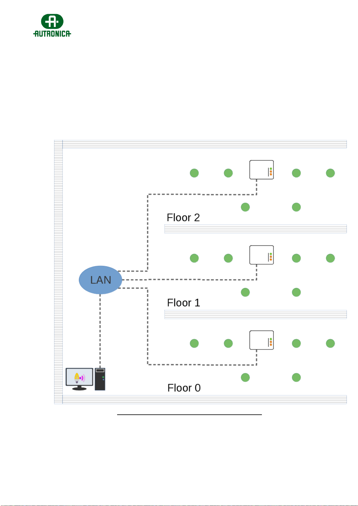
1. Install the Gateway to its given location and activate it.
2. Once the Gateway is active, it will start transmitting signal beacons. Those beacons are
tracked by other wireless devices to detect and join a wireless network, but can also be
tracked by the 116-GR-7605/V2 RSSI Tester, which can read and display the received
signal level (Received Signal Strength Indication), with LED levels (1 to 5).
3. Move to a -close to the Gateway- emergency luminaire installation position (<25m) and
measure the signal with the “116-GR-7605/V2” in RSSI Tester mode. Activate it (3”
push), and then push the button once again to change to RSSI Tester indication mode.
The red LED on the left will immediately turn on. Within a few seconds, more LEDs will
light, as long as there is some signal present in that position. Wait for at least 1 minute
for a more precise measurement. If the indication level is 3 LEDs and above, the
position is good for installing a wireless device and the connection quality will be within
good levels. Then you can install the wireless device (luminaire) and activate it. When
the signal is lower, consider adding another wireless device in between (a wireless
luminaire or a network extender) to enhance the signal reception.

Quick Installation Guide –116-GR-7600/V2 Wireless Emergency Lighting
[11]
WEL_qInstallGuide_V2_rv3 - Autronica.docx
Figure 6: RSSI Tester measurement
4. In the meantime, when installing a wireless device into place, take notes regarding its
location and match its UID address (you can use the extra UID stickers included in their
package). This will help for a graphical installation plan later.
5. After installing and activating the first wireless device (luminaire) into position, proceed
to 2nd closest installation position and measure the signal with the same method. Note
that every time you activate a new device, the signal level reading indicates the signal
level received from the Gateway or from any other of the wireless devices installed
(which operate as repeaters). Continue similarly until the completion of the installation.
6. As an option, you can confirm if a wireless emergency luminaire has joined the wireless
network by observing the LED indicators on wireless adapters inside. Blinking of both
LD2 and LD3 (green) indicates successful connection, while the blinking rate indicates
quality. When LD3 is turned off there is no connection. See corresponding manual
regarding wireless adapter indication.

Quick Installation Guide –116-GR-7600/V2 Wireless Emergency Lighting
[12]
WEL_qInstallGuide_V2_rv3 - Autronica.docx
Figure 7: LED indications on wireless adapter
7. When the installation of the wireless devices has been completed, create a graphical
installation plan of the entire installation, on paper or digital. This step is very important
for later commissioning, maintenance and trouble-shooting. A simple picture of a floor-
plan can be seen below:
Figure 8: Graphical floor-plan example
The picture above is only an example; you may create your own graphical floor-plan for
your own purpose and needs.
8. When the installation is completed along with a detailed graphical installation plan, the
commissioning procedure can start. See the corresponding commissioning guide of
Wireless Emergency Lighting.
Table of contents