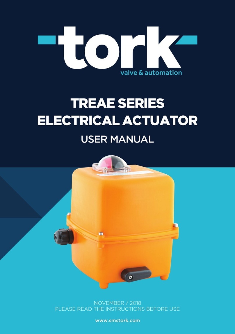
Ava 20 Series Installation guide

Join the orange and grey revolution
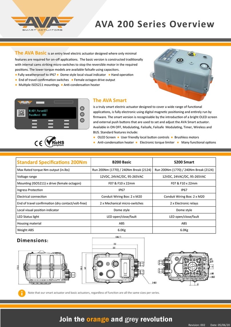
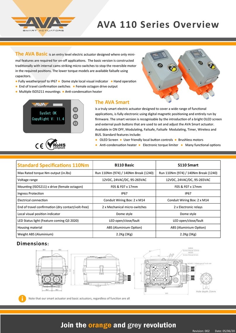
AVA 20 Series Overview
The AVA Basic is an entry level electric actuator designed where only minimal
features are required for on-o applicaons. The basic version is constructed tradionally
with internal cams striking micro-switches to stop the reversible motor in the required
posions. The lower torque models are available failsafe using capacitors.
● Fully weatherproof to IP67 ● Dome style local visual indicator ● Hand operaon
● End of travel conrmaon switches ● Female octagon drive output
● Mulple ISO5211 mounngs ● An-condensaon heater
The AVA Smart
is a truly smart electric actuator designed to cover a wide range of funconal applica-
ons, is fully electronic using digital magnec posioning and enrely run by rmware.
The smart version is recognisable by the introducon of a bright OLED screen and exter-
nal push buons that are used to set and adjust the AVA Smart actuator. Available in
ON OFF, Modulang, Failsafe, Failsafe Modulang, Timer, Wireless and BUS. Standard
features include:
● OLED Screen ● User friendly local buon controls ● Brushless motors
● An-condensaon heater ● Electronic torque limiter ● Many funconal opons
Standard Specicaons 20Nm B20 Basic S20 Smart
Max Rated torque Nm output (in.lbs) Run 20Nm (178) / 25Nm Break (221) Run 20Nm (178) / 25Nm Break (221)
Voltage range 12VDC, 24VAC/DC, 95-265VAC 12VDC, 24VAC/DC, 95-265VAC
Mounng (ISO5211) x drive (female octagon) F03/04/05 x 14mm F03/04/05 x 14mm
Ingress Protecon IP67 IP67
Electrical connecon Pre Wired 0.8m Flying Lead Pre Wired 0.8m Flying Lead
End of travel conrmaon (dry contact/volt-free) 2 x Mechanical micro-switches 2 x Electronic relays
Local visual posion indicator Dome style Dome style
LED Status light - Coming Q3 2020 LED open/close/fault LED open/close/fault
Housing material ABS (Aluminium Opon) ABS (Aluminium Opon)
Weight ABS (Aluminium) 0.8Kg (1.2Kg) 0.8Kg (1.2Kg)
Revision: 002 Date: 05/06/20
Note that our smart and basic actuators, regardless of funcon, are all the same size per series.
Dimensions:X

Join the orange and grey revolution
POWER CONSUMPTION FOR SERIES 20 ACTUATORS
Rated Voltage 95-265VAC/DC (50/60Hz) 24VAC/DC (50/60Hz) DC 12VDC 24V
Voltage Range AC: 95-265V DC: 100-300V AC: 18-26V DC: 22-28V 10-15VDC: 22-28V
20 Series Torque Nm (Break) 20 (25) 20 (25) 20 (25)20 (25)
20 Series Power (W) All Series 15W 15W 15W15W
20 Series Power (W) Failsafe 36W 36W 36W36W
20 Series Power (W) Hi Speed 85W 85W 85W85W
20 Series Peak Current 0.94A 0.94A 0.94A0.94A
20 Series On O Fuse 2A 1A 2A2A
20 Series Failsafe/HiSpeed Fuse 2A 4A/10A 4A/10A4A/10A
20 Series Run me 10 Seconds Open - Close 10 Seconds Open - Close 15 Seconds Open - Close10 Seconds Open - Close
20 Series Hi Speed Run me 3-5 Seconds Open - Close 3-5 Seconds Open - Close N/A1 Second Open - Close
20 Series Heater Power (W) 0.6W 0.6W 0.6W0.6W
STANDARD FEATURES:
Operang frequency Not connuous, allow ≥ 1 minute between cycles
Posion conrmaon Mechanically driven dome style visual 2 colour indicator
Mounng restricon Do not install underslung/upside down. Can install upright horizontally or vercally.
End Posion indicaon Micro-switches operated by adjustable internal cams , set slightly ahead of the nal motor stop posion.
ISO:5211 F03/04/05 - Note F04 is at 45 degree
Working Angle Factory set at 90⁰ ±2⁰, maximum angle of rotaon 360⁰ unless mul turn series.
Manual operaon Yes, by hexagonal wrench (supplied in clip) when no power is being applied.
Female drive 14mm x 15mm deep
Ingress protecon IP67
Max media temp ≤ 80C
LED Light - Coming Q3 2020 Green shows actuator OPEN - Red shows actuator is CLOSED - Blue shows actuator has an ALERT , see wiring diagram
Ambient temp -20 to +60C (ABS) Non-operang temp ; ≤ -40C to ≥80C
Wiring Connecvity 2 x M10 weatherproof gland with ying lead.
Ambient humidity 5-95% RH non-condensing
Explosion proof No, prohibited. Do not use in hazardous areas
Housing Plasc (ABS) - opon available for aluminium housing.
Weight With standard ABS housing 1.2Kg.
Warranty Basic Series Basic series carries standard 1 year 20,000 operaons warranty. Terms and condions apply.
Warranty Smart Series Smart series carries upgraded 2 year 60,000 operaons warranty. Terms and condions apply.
AVA 20 Series Specification
Item MaterialParts
1ABS Actuator
2Transparent ASIndicator
3Screw x 4 304
4Manual Sha 304
5Oil Seat NBR
6Label PVC
7Wrench Fixed ABS
8Hexagon Wrench Steel
9Weatherproof Cable connector Nylon
10 Cover Seal NBR
1
2
3
4
6
7
8
9
10
Revision: 002 Date: 05/06/20

Note: Modulang Hi Speed versions also available.
Note: Basic 20 series available as 220VAC, 110VAC, 24VAC and 24VDC single voltage opons.
Join the orange and grey revolution
AVA 20 Series Overview
SERIES SERIES OVERVIEW OF OUR 20NM ELECTRIC ACTUATORS SALES
Revision: 002 Date: 05/06/20
ON OFF QUARTER TURN ACTUATORS
B205 95-265VAC BASIC SERIES ON OFF MULTI VOLTAGE
B206 24VAC/DC BASIC SERIES ON OFF MULTI VOLTAGE
S2010-595-265VAC SMART SERIES ON OFF MULTI VOLTAGE
S2010-624VAC/DC SMART SERIES ON OFF MULTI VOLTAGE
FAILSAFE QUARTER TURN ACTUATORS
B245 95-265VAC BASIC SERIES FAILSAFE MULTI VOLTAGE
B246 24VAC/DC BASIC SERIES FAILSAFE MULTI VOLTAGE
S2014-595-265VAC SMART SERIES FAILSAFE MULTI VOLTAGE
S2014-624VAC/DC SMART SERIES FAILSAFE MULTI VOLTAGE
MODULATING QUARTER TURN ACTUATORS - 4-20mA/ 0-10V + other inputs
S2025-595-265VAC SMART SERIES MODULATING MULTI VOLTAGE
S2025-624VAC/DC SMART SERIES MODULATING MULTI VOLTAGE
S2026-595-265VAC SMART MODULATING FAILSAFE MULTI VOLTAGE
S2026-624VAC/DC SMART MODULATING FAILSAFE MULTI VOLTAGE
HI SPEED QUARTER TURN ACTUATORS -
S2019-595-265VAC SMART SERIES HI SPEED MULTI VOLTAGE
S2019-624VAC/DC SMART SERIES HI SPEED MULTI VOLTAGE
S2029-595-265VAC SMART MODULATING HI SPEED MULTI VOLTAGE
S2029-624VAC/DC SMART MODULATING HI SPEED MULTI VOLTAGE
Note other funconality available includes Timer Modbus and Wireless opons. Contact Reseller for details

Join the orange and grey revolution
AVA 20 Series Wiring
BASIC ACTUATORS:-
Standard wiring for Basic actuators used for all
series. Failsafe achieved using internal Super
Capacitor opon. Dierent wiring opons available.
WIRING BASIC ON OFF / HI SPEED / FAILSAFE TYPE: B3S
WIRING SMART ON OFF / HI SPEED / FAILSAFE TYPE: B3J
WIRING SMART MODULATING / HI SPEED / FAILSAFE TYPE: 4-20/0-10
SMART ACTUATORS:-
Smart actuators ulised Digital Encoder and
electronic relays. Feedback digitally set using
rmware. Dierent wiring opons available.
SMART MODULATING ACTUATORS:-
Smart actuators require resistor ng as shown
in diagram. Feedback must be connected for
actuator to work correctly.
Revision: 002 Date: 05/06/20
Note that we currently cannot oer Hi Speed Failsafe funconality due to limitaons in Capacitor technology used.
Note that we currently cannot oer Hi Speed Failsafe funconality due to limitaons in Capacitor technology used.
Note that we currently cannot oer Hi Speed Failsafe funconality due to limitaons in Capacitor technology used.

Join the orange and grey revolution
AVA 20 Series Wiring
SMART MODBUS ACTUATORS:-
Available as on o, failsafe and modulang
using Modbus RS485 or CANBUS. See website
for addional informaon and user guides.
WIRING SMART MODBUS RS485 ON OFF / FAILSAFE TYPE: RS485
WIRING SMART TIMER SERIES ON OFF / FAILSAFE TYPE: TIMER
WIRING SMART WIRELESS ON OFF / FAILSAFE LORA RF433/868/915MHZ TYPE: LORA
SMART TIMER ACTUATORS:-
You only need power, the actuators opening and
closing schedule is set via onboard rmware.
24/7 x 365 mer upto 60 operaons per day.
SMART RF/ WIRELESS ACTUATORS:-
Power local to actuator and control via RF Fob.
For installaons where power is available, but
wired control is not.
Revision: 002 Date: 05/06/20
Note that all of the following opons are typically ‘Specials’ and not available from stock. Contact your reseller for details.

Join the orange and grey revolution
AVA 20 Series Wiring
PRE WIRED ACTUATORS:-
Due to the compact design of our actuators, our Series 10, 20 and 50 have pre
wired, typically 0.8m long cables that contain your power, feedback and
earthing cores. Unless ed with a special opon, such as Alarm Relays, the
actuators are supplied with a 7 pin connector. This can be removed if not
required or to be ulised. This does NOT invalidate the warranty or eect the
actuator. Flying lead can be from 1m to 20m. Speak to our team about your
requirement.
WIRING SERIES 10, 20 AND 50 PRE WIRED ACTUATORS WIRING
WIRING SERIES 80-110 AND 200 –400 WIRING BOX ACTUATORS WIRING
WIRING BOX - TERMINAL STRIP ACTUATORS:-
Our larger actuators have 2 x M20 Conduit Glands on the back of the actuator.
The wiring box is removed from the actuator base which will expose the
terminal strip for you to terminate your cables. This will be typically a 9 pin
terminal design to allow for addional cores for Alarm Relays. Refer to manual
for Fuse requirements. Feedback signal contact load capacity 0.1A/250VAC
0.5A/30VDC.
WIRING SERIES 20-400 AVIATION PLUG IP68 CONNECTOR OPTION WIRING
WIRING BOX - ’AVAIATION PLUG’ IP68 OPTION:-
Our inline connectors oer a plug and play weather proof connector.
This is becoming more popular for customers looking to remove the
need to install a juncon box between the actuator and panel. This IP68
weatherproof connector is an ideal choice for external applicaons.
Speak to our sales team today about opons on this connector type.
Revision: 002 Date: 05/06/20
Note that the 20 Series 7 core cables are 16 wire Gauge as standard and our 50 series is 12 wire Gauge as standard.
Note that the 80-110 and 200-400 terminal strip is designed to accept 12 wire Gauge cables. We can supply prewired if required.
Note the ’Aviaon Plug’ is a special execuon on request at this me. Speak to your reseller for more informaon.

Join the orange and grey revolution
AVA Basic Series - CAMS
Adjusting valve location
instructions
1. ADJUSTING FULL CLOSE POSITION
Rotate the valve to full close posion with handle.
• Since the valve has gone through “factory default seng”, this step can be omied if it the adjustment is slight.
• Detach cambered indicang dial, loosen xing screw L3 of indicang dial support, turn reinforcing rib as shown in diagram 5,
perpendicular to the ow direcon of valve, then screw up L3 and buckle up cambered indicang dial.
• Loosen xing screw L1 of cam 1, drive cam 1 to rotate clockwise and trigger micro switches K2, K1 to move in turn and make
sound. When K1 moves and makes sound, stop adjustment. Then screw up xing screw L1.
• Noce 1: The default is that rotang in clockwise direcon means closing ,and rotang in anclockwise direcon means
opening.
• Noce 2: B3P does not have K2,K4 micro switch.
Cauon: When screwing up L3, the torque≤0.5 NM, otherwise it will damage locang driving gear.
In the process of adjustment, do not over ghten screws, otherwise it will damage screw threads or other parts.
2. ADJUSTING FULL OPEN POSITION
• Rotate the valve to full open posion with handle.
• Loosen xing screw L2 of cam2, drive cam 2 to rotate anclockwise and trigger micro switches K4, K3 to move in turn and
make sound. When K3 moves and makes sound, stop adjustment. Then screw up xing screw L2.
3. WIRING
• Aer modifying, connect the circuit according to the wiring label on the box cover. Aer conrmaon, you can do power test.
4. ELECTRICAL TEST
• Mainly check the consistence of on and o between the actuator and the valve body. At the same me, please check whether
the valve is full close or not. Special tesng device is recommended
Diagram 1 Diagram 2 Diagram 3 Diagram 4 Diagram 5
Note you should only remove the cover on instrucon
from your AVA reseller or AVA technical support agent
as it may invalidate warranty.
NOTE - Smart actuators do not have internal cams and micro switches, therefore posion adjustment is via rmware. See
actuator Firmware User Guide for detailed screen by screen guide including how to change working angle and feedback.
Revision: 002 Date: 05/06/20

Join the orange and grey revolution
AVA 20 User Guide
IOMS SMART ACTAUATOR OLED SCREEN USER GUIDE - THE BASICS OLED
MHold for 3 seconds to enter MENU Mode. Enter 333 Password
K2
K3 Hold for 3 seconds to enter LOCAL CONTROL. Enter 111 Password
ALLMK Hold all 3 buons and enter RESET MODE. Enter 6666 Password
Our Smart series actuators ulise our smart screen and menu system using a colour OLED screen. Not only does the
screen display the actuator status, set posion from PLC/Controller and actual posion. The screen also can display
any ALERTS such as an over torque situaon. You can use the touch buons to enter the Menu mode, customising
working angle, speed, accuracy to name just a few of the customisable opons. You can also use the Local Control
mode or Manual Mode to use the buons to open and close the actuator locally via the touch buons. Full screen
by screen Firmware guide available on request.
You can use the M buon once into the Menu Mode to move through the dierent screens.
You can use K2 to move up and down through the opons
You can use K3 to move le and right through the opons.
For ALL actuators, you can electronically set the
Open and Close posion via the rmware. This
example shows a Modulang Actuator screen,
the user can set the 4mA posion or the closed
posion.
For our Failsafe actuators, on inially powering,
you will see the screen display the Capacitor
Charge %. You can also set the % of charge need-
ed as a minimum, the failsafe posion to fail
OPEN or CLOSED.
Once all the sengs and adjustments have
changed, you can exit via the screen above and
press the K3 buon (boom buon) this will
show the message ‘Saved’ which means the
changes made are now live and will reect in
Revision: 002 Date: 05/06/20
Note the above are just some of the Firmware opons available to customise the actuator funcon. This will vary on series and funcon.
You can set the B33 posion. This is used for
seng a 3rd Posion. Either on a 3 way valve or
simply as a 3 point control valve. For example 0-
90-180 degrees or 0-45-90 degrees. For Failsafe
actuators you can also use the 3ed posion as
the failsafe posion.

Join the orange and grey revolution
AVA Wiring Options
AVA Wiring Options
As you will see from the previous page, our AVA electric actuators are capable of various
wiring conguraons based on what your applicaon requires. As detailed, our standard
for our Basic actuators is what we call B - B3S which is a SPDT with volt free posion
conrmaon. Our Smart actuators use E - B3J which is SPDT Relay posion conrmaon.
Remember that all of our Smart units don’t use mechanical cams and micro switches. A
digital encoder and relays are used. The following are some of the addional wiring dia-
grams that you might nd of interest, that are available for our Smart actuators including
3 and 4 posion wiring conguraons.
Check with your AVA reseller for lead me on non stock wiring conguraons.
Wiring G: BD3J - SPST / Relay Posion Conrmaon Wiring P2: 4-20ma Failsafe with alarm output
Wiring J: B33J 2 x SPST / Relay Posion Conrm (3 posion) Wiring M: B44 SPST / No posion conrmaon (4 posion)
Wiring F: B3JA 2 x SPDT/Relay Posion Conrm + Alarm Output Wiring U5: 0-10V Control/ Feedback with Alarm Output
Revision: 002 Date: 05/06/20
You may see a Pink wire, this is disconnected
internally, you do not need this wire.

Join the orange and grey revolution
INSTALLATION, OPERATION &
MAINTENANCE
AVA Actuator IOM’s
Here are some general instrucons relang to the Installaon, Operaon and Maintenance
of our electric actuators.
We also cover some of the Frequently Asked Quesons by our customers over the years
from around the world.
Check out our website for all the latest Technical Support documents including product
videos and for our Smart Actuators, our screen by screen user guides.
www.avactuators.co.uk
Revision: 002 Date: 05/06/20
SCAN FOR TECH
SUPPORT
SUPPORT INSTALLATION, OPERATION & MAINTENANCE
Cover No need to remove cover, doing so can invalidate your warranty
Heater The heater opon is prewired. When the actuator is powered, the heater is working
Orientaon Install vercally or horizontally upright, not to be installed underslung/upside down
Explosion Proof All series are suitable for SAFE AREA use only. Series 20 available as EX Rated
IP Rang IP67 weather proof, we advise against jeng/pressure washing actuators
Connector If your actuator is received with the white connector, you can remove it and terminate cable
Warranty Basic Series is 12 months 20,000 operaons. Smart Series is 24 months 60,000 operaons
End of Travel All actuators have end of travel limit switches except Modulang actuators, see below
4-20mA Output Smart Modulang actuators have posion feedback only, they don’t have end of travel feedback
Wiring Box Series 80-400Nm ulise a wiring box at the rear of the actuator. Remove to wire actuator
Maintenance All series of the actuators maintenance free. We recommend actuators are operated daily.
Keep Powered Yes, we recommend the actuators are powered at all mes to ensure the heater and feedback operate
SUPPORT FREQUENLTY ASKED QUESTIONS AND COMMON FAULT DIAGNOSIS
Capacitor Charge When inially using Failsafe actuators, allow short period of me for the actuator to charge capacitor.
Alert on Screen Smart actuators show ALERT when actuator has ‘Excessive Valve Torque’ or Motor Failure
No Control If your Modulang Actuator shows ‘NoCtrl’ check wiring, your actuator cannot see the modulang input
Feedback Error Ensure you are using resistors for Modulang actuators as per wiring diagram.
3rd Posion To put actuator into B33 or 3rd posion, apply power to both Red and Black at same me.
Adjust Angle Basic You can adjust the working angle of the actuator through adjusng the cams in the Basic series
Adjust Angle
Smart
You can use the rmware to set the working angle and this will also set the end of travel limit switches
LED Modulang Series 20-110 where LED ed will only show the LED on alarm. 200-400 series will also show open/close
Actuator Spins
360
If a Basic actuator and actuator rotates 360 degrees, internal micro switches are likely damaged
Screen isn't on For Smart actuators, check wiring and ensure excess voltage not applied. If ok, contact our support team
This manual suits for next models
20
Other Ava Controllers manuals
