Bender PRC470 Series User manual

1
Steuer- und Anzeigegerät
für RCMS- und EDS-Systeme
Bestimmungsgemäße Verwendung
Das Steuer- und Anzeigegerät PRC470 wird zur zentralen Steue-
rung von Isolationsfehlersucheinrichtungen EDS470, EDS473
oder von Differenzstrom-Suchsystemen RCMS470 eingesetzt.
Das PRC470 steuert bis zu
●30 Differenzstrom-Auswertegeräte RCMS470-12 bzw.
●30 Isolationsfehler-Auswertegeräte EDS47x-12
Das PRC470E steuert bis zu
●60 Differenzstrom-Auswertegeräte RCMS470E-12 bzw.
●60 Isolationsfehler-Auswertegeräte EDS47xE-12
Aufgaben des PRC470:
●Zentrale Steuerung von EDS47x und RCMS470-Systemen
●Datenaustausch per BMS-Bus
●Anzeige der fehlerbehafteteten Abgänge und des aktuel-
len Fehlerstromes (oder Prüfstromes) pro Abgang
●Einstellung unterschiedlicher Messstromwandlertypen
●Individuelle Einstellmöglichkeiten für jedes Auswertegerät
●Anpassung des Systems an Netzstörungen (EDS47x)
●Steuerung von Auswertegeräten.
Die Synchronisation und Steuerung erfolgt über BMS-Bus.
Dieser Beipack informiert über den Einsatz des PRC470 in
RCMS470-Systemen. Der Einsatz in Isolationsfehlersucheinrich-
tungen EDS470, EDS473 ist in den jeweiligen Bedienungshand-
büchern beschrieben.
Dieser Beipack beschreibt PRC470 ab der eingebauten Software-
version 2.13.
Sicherheitshinweise allgemein
Montage, Anschluss und Inbetriebnahme nur durch Elektrofach-
kraft!
Beachten Sie unbedingt:
●die bestehenden Sicherheitsvorschriften und
●das beiliegende Blatt „Wichtige sicherheitstechnische Hin-
weise für BENDER-Produkte“.
Funktionsbeschreibung
Das PRC470 erfüllt folgende Funktionen:
●Einstellung des Speicherverhaltens
●Einstellung der Arbeitsweise des Alarmrelais
●Anzeige der Messstromwandlerabgänge, in denen die Ver-
bindung zum Messstromwandler unterbrochen oder kurz-
geschlossen ist.
●Manuelle Anwahl bestimmter Messstromwandlerabgänge
●Prüffunktion zum Test aller über den BMS-Bus angeschlos-
senen Geräte einschließlich der Prüfung der Messstrom-
wandlerkreise.
●Einstellung, ob am jeweiligen Eingang eines RCMS470-12
bzw. EDS47x-12 ein Messstromwandler angeschlossen ist
Control and indicating device
for RCMS and EDS systems
Intended use
The control and indicating device PRC470 is used for the central
control of the insulation fault location systems EDS470, EDS473
or the residual current monitoring system RCMS470. The PRC470
controls up to
●30 residual current evaluators RCMS470-12 or
●30 insulation fault evaluators EDS47x-12
The PRC470E controls up to
●60 residual current evaluators RCMS470E-12 or
●60 insulation fault evaluators EDS47xE-12
Intended use of the PRC470:
●Central control of EDS47x and RCMS470 systems
●Data exchange via BMS bus
●Indication of faulty subcircuits and the present faulty cur-
rent or (test current) per subcircuit
●Setting of different types of meas. current transformers
●Individual settings for each evaluator
●Adaptation of the system to system interferences (EDS47x)
●Control of evaluators.
Synchronisation and control takes place via BMS bus.
This documentation provides information on the utilization of
the PRC470 in RCMS470 systems. Details relating to utilization in
the insulation fault location systems EDS470 and EDS473 can be
found in the respective operating manuals.
This documentation describes the PRC470 with the installed soft-
ware version 2.13.
General safety instructions
Installation, connection and commissioning of electrical equip-
ment shall only be carried out by qualified electricians!
Particular attention shall be paid to:
●the current safety regulations and
●the enclosed sheet "Important safety instructions for
Bender products“.
Description of functions
The PRC470 is equipped with the following functions:
●Setting of the storage properties
●Setting the operation of the alarm relay
●Indication of measuring current transformer subcircuits in
which the connection to the measuring current trans-
former is interrupted or short-circuited.
●Manual selection of specific measuring current trans-
former subcircuits.
●Test function to test all devices connected via the BMS bus
including the testing of the meas. current transf. circuits.
●Setting, as to whether or not a measuring current trans-
former is connected to the respective input of an
PRC470, PRC470E
108001 / 11.2004
Deutsch English

2108001 / 11.2004
PRC470, PRC470E
RCMS470-12 or EDS47x-12 .
●Deleting all alarm signals
Additional functions in the RCMS system:
●Setting the individual response values for each channel
●Setting the prewarning level at between 10 and 100 % of
the response value
●Setting a factor
●Indication of the current act. value of the residual current
●Indication of the measuring current transformer subcir-
cuits in which the response value of the residual current
has been exceeded and indication of the corresponding
residual current
Additional functions in the EDS system
●Setting the transformer type (closed or separable)
●Indication of subcircuits with insulation faults
●Manual starting and stopping of insulation fault location
●Setting an extension of the measuring time
The PRC470 is capable of controlling and monitoring the entire
system from a central location.
Operating elements
Figure 1: Operating elements
Legende of operating elements
Installation and connection
Installation
The device is suitable for:
●mounting into standard distribution panels according to
DIN 43 871 or
●DIN rail mounting in compliance with IEC60715:1995-10 or
●screw fixing.
1 Alarm LED lights up when the residual current in the connected evaluators
exceeds or falls below the set response value (common alarm).
2 RS485 LED indicates activity on the BMS bus.
3 Control keys UP, DOWN, ENTER
Make sure that the system is off circuit prior to in-
stallation and before commencing work on the
connecting cables.
Failure to do so exposes the personnel to the dan-
ger of electric shock.
In addition, the electrical installation could be
damaged and the device destroyed.
oder nicht.
●Löschen aller Alarmmeldungen
Zusätzliche Funktionen im RCMS-System:
●Einstellung der individuellen Ansprechwerte für jeden
Kanal
●Einstellung einer Vorwarnstufe zwischen 10 und 100 % des
Ansprechwertes
●Einstellung eines Faktors
●Anzeige der aktuellen Istwerte des Differenzstromes
●Anzeige der Messstromwandlerabgänge, in denen der
Ansprechwert des Differenzstromes überschritten wurde
und Anzeige des entsprechenden Differenzstromes
Zusätzliche Funktionen im EDS-System
●Einstellung des Wandlertyps (geschlossen oder teilbar)
●Anzeige von Abgängen mit Isolationsfehlern
●Manuelles Starten und Stoppen der Isolationsfehlersuche
●Einstellung einer Messzeitverlängerung
Mit dem PRC470 kann der gesamte Anlagenbereich von einer
zentralen Stelle aus überwacht und gesteuert werden.
Bedienelemente
Abb. 1: Bedienelemente
Legende der Bedienelemente
Montage und Anschluss
Montage
Das Gerät ist für folgende Einbauarten geeignet:
●Installationsverteiler nach DIN 43 871 oder
●Schnellmontage auf Hutprofilschiene nach
IEC60715:1995-10
●oder Schraubmontage.
1 Alarm-LED leuchtet, wenn ein Ansprechwert an einem der angeschlosse-
nen Auswertegeräte über- oder unterschritten wird (Sammelalarm).
2 RS485-LED zeigt Aktivitäten auf dem BMS-Bus.
3 Bedientasten UP, DOWN, ENTER
Stellen Sie vor Einbau des Gerätes und vor Arbei-
ten an den Anschlüssen des Gerätes sicher, dass
die Anlage spannungsfrei ist.
Wird dies nicht beachtet, so besteht für das Perso-
nal die Gefahr eines elektrischen Schlages.
Außerdem drohen Sachschäden an der elektri-
schen Anlage und die Zerstörung des Gerätes.
A1 A2
GND IN1 IN2 IN3 IN4 O1+ O1- O2+ O2-
A B 21 22 2411
PRC470
12 14
ALARM RS485
RS485
V. 2.x
12
3

3
108001 / 11.2004
PRC470, PRC470E
Dimension diagram
Figure 2: All dimensions in mm
Connection
Connect the device in accordance with the wiring diagram in the
manual that comes with the RCMS system. Please observe the
tightening torque for terminal screws (see Technical data).
Connections
Legend to the wiring diagram
1 Control inputs EDS470 (EDS473) for system start
2 Connection for external Reset key
3 Connection for external Test key
4
Connection for testing device PGH470.., is only applied with EDSsystems in
order to provide the necessary impulse against earth for insulation fault
location in IT systems.
5Alarm relays switch when the residual current exceeds or falls below the
set response value (common alarm)..
F Fuse(s) supply voltage
Maßbild
Abb. 2: alle Maße in mm
Anschluss
Schließen Sie das Gerät entsprechend dem Anschlussplan in der
Anleitung des RCMS-Systems an. Beachten Sie dabei das Anzugs-
drehmoment für die Klemmschrauben (siehe Technische Daten).
Anschlüsse
Legende zum Anschlussschaltbild
1 Steuerungseingänge EDS470 (EDS473) für Systemstart
2 Anschluss für externe Reset-Taste
3 Anschluss für externe Prüftaste
4
Anschluss für Prüfgerät PGH470.., wird nur bei EDS-Systemen eingesetzt,
um den zur Erdschlusssuche imIT-Netz notwendigen Impuls gegen Erde zu
liefern.
5Alarmrelais schalten, wenn ein Ansprechwert über- oder unterschritten
wird (Sammelmeldung).
F Sicherung(en) Speisespannung
A1 A2 GND IN1 IN2 IN3 O1+ O1- O2+ O2-IN4
US
(+)
(-)
Prüfgerät PGH470
(nur be EDS470-Systemen)
AB
BMS
F
6A
Test device PGH470
(only for EDS470 systems)
11 21
12 14 22 24
s ehe Typensch ld
see nameplate
A1 A2
GND IN1 IN2 IN3 IN4 O1+ O1- O2+ O2-
A B 21 22 2411
PRC470
12 14
ALARM RS485
RS485
V. 2.x
RCMS470...,
SMO..., EDS47x
2
2
13
4
5

4108001 / 11.2004
PRC470, PRC470E
Anschluss bei Einsatz in einem EDS47x-System
Verbinden Sie PRC470, PGH47x und EDS47x-12 über den BMS-
Bus. Das PRC470 ist werksseitig als Master eingestellt. Die ande-
ren Geräte sind Slaves.
Start der Isolationsfehlersucheinrichtung
Der Start sollte durch einen potentialfreien Ausgangskontakt
(Wechsler) des Isolationsüberwachungsgerätes erfolgen. Der
Schließer kann dabei an die Klemmen GND / IN1...IN2 des PRC470
(oder alternativ des PGH47x) angeschlossen werden. Wichtig:
Niemals die Eingänge IN1 und IN2 gleichzeitig verwenden!
●Anschluss des Schließerkontaktes (21/24) an die Klemmen
GND und IN1: Die Isolationsfehlersuche läuft solange, wie
der Kontakt geschlossen ist. Nach einem Lauf des Systems
von mindestens 5 Minuten wird eine Pause von 5 Minuten
eingelegt, in der das Isolationsüberwachungsgerät neue
Messwerte erfassen kann. Ein Durchlauf (maximal 360
Wandler) dauert in Netzen mit geringen Störungen min-
destens 5 Minuten.
Das EDS47x-System kann gestoppt werden durch:
– Öffnen von GND/IN1
– Betätigen der STOP-Taste am PGH47x
– Softwarestop im Menü 2 (EDS START) des PRC470
– Schließen GND / IN3 am PGH47x
●Anschluss des Schließerkontaktes (21/24) an die Klemmen
GND und IN2: Die Isolationsfehlersuche wird für mindes-
tens 5 Minuten gestartet und danach angehalten. Um zu
starten, muss der Eingang für mindestens 6 Sekunden
geschlossen sein. Das EDS47x-System kann gestoppt wer-
den durch:
– Betätigen der STOP-Taste am PGH47x
– Softwarestop im Menü 2 (EDS START) des PRC470
– Schließen von GND / IN3 am PGH47x
●Anschluss des Öffnerkontaktes (21/22) an die Klemmen
GND und IN3: Prüftaktunterdrückung. Es wird kein Prüftakt
ausgegeben. Diese Funktion wird benötigt, wenn die Iso-
lationsfehlersucheinrichtung mehrere IT-Systeme über-
wacht und dabei zentral von einem PRC470 gesteuert
wird. In diesem Fall darf nur das Prüfgerät PGH47x einen
Prüftakt ausgeben, in dessen IT-System der Isolationsfeh-
ler aufgetreten ist.
Hinweis: Diese Art des Anschlusses ist nur in gekoppelten
Netzen sinnvoll!
Sichern Sie die Speisespannung Usim IT-System zwei-
polig ab! Nur so ist im Falle des zweiten Fehlers sicher-
gestellt, dass gefähliche Fehlerströme abgeschaltet
werden.
Connection when applied in an EDS47x system
Connect PRC470, PGH47x and EDS47x-12 via the BMS bus. The
PRC470 is set as master at the factory. The other devices are
slaves.
Start the insulation fault location system
The start should be effected through an isolated output contact
(changeover contact) of the insulation monitoring device. Here,
the make contact can be connected to the terminals GND /
IN1...IN2 of the PRC470 (or alternatively, the PGH47x). Important:
Never use inputs IN1 and IN2 at the same time!
●Connecting the make contact (21/24) to the terminals
GND and IN1: insulation fault location will run as long as
the contact is closed. When the system has been running
for 5 minutes there will be a 5-minute break during which
the insulation monitoring device can record new
measurement values. A complete run (max. 360
transformers) takes at least five minutes in networks with
low interference levels.
The EDS47x system can be stopped by:
– Opening GND/IN1
– Pressing the STOP key on PGH47x
– Software stop in menu 2 (EDS START) of PRC470
– Closing GND / IN3 at the PGH 47x
●Connecting the make contact (21/24) to the terminals
GND and IN2: insulation fault location will be started for at
least 5 minutes and then stopped. To start, the input must
be closed for at least 6 seconds. The EDS47x system can be
stopped by:
– Pressing the STOP key on PGH47x
– Software stop in menu 2 (EDS START) of PRC470
– Closing GND / IN3 at the PGH 47x
●Connecting a break contact (21/22) to the terminals GND
and IN3: test pulse suppression. There will be no test pulse.
This function is required when the insulation fault location
system monitors several IT systems and is controlled cen-
trally from a PRC470. In this case, a test pulse shall only be
output by the testing device PGH47x in the IT system in
which the insulation fault occurred.
Note: This type of connection is only meaningful in cou-
pled networks!
Voltage supply Usin IT systems requires two fuses!
This is the only way of guaranteeing that dangerous
faulty current is switched off in the event of a second
fault.

5
108001 / 11.2004
PRC470, PRC470E
Commissioning
Please make sure that the device is properly connected before
commissioning.
Operating the PRC470
The PRC470 is operate via three keys. When the supply voltage is
switched on, the control and indicating device PRC470 displays a
"Start screen" for approx. 5 seconds. The device type, the
Firmware version and the manufacturer's name are then dis-
played.
Control keys of the PRC470
Software reset
A software reset restarts the PRC470. Saved alarm signals will not
be deleted.
Press the keys ↑and simultaneously for more than a second.
The Start screen will be displayed.
Settings on the PRC470
The start screen is followed by the standard display. The PRC470
automatically recognizes which system it has been applied to and
shows the name of the system on the display.
In the RCMS system, all channels will now be monitored continu-
ously in accordance with the "scanning principle".
To change the settings, press the key. The menu shown above
will be displayed for a few seconds. Then “m1: monitor” will be
displayed as the first menu than can be set.
The PRC470 is a constituent of an RCMS470 or
EDS470 system. Commissioning must be carried out
in accordance with the instructions in the manual
that comes with the RCMS470 or EDS470 system.
Enter: confirm the selected menu item
↓scroll down the menu to further functions; and exit the Settings menu in
"m1"
↑scroll up the menu to further functions; and exit the Settings menu in
"m10"
RCMS-SYSTEM
(menu: )
RCMS-SYSTEM
. . . busy . . .
Inbetriebnahme
Kontrollieren Sie vor der Inbetriebnahme den ordnungsgemäßen
Anschluss des Gerätes.
Bedienen des PRC470
Die Bedienung des PRC470 erfolgt über 3 Tasten. Bei Zuschalten
der Versorgungsspannung zeigt das Steuer-und Anzeigegerät
PRC470 für ca. 5 Sekunden einen „Startbildschirm“. Darin werden
der Gerätetyp, die Version der Firmware und der Herstellername
gezeigt.
Bedientasten des PRC470
Software-Reset
Durch einen Software-Reset bewirken Sie einen Neustart des
PRC470. Gespeicherte Alarmmeldungen werden nicht gelöscht.
Drücken Sie die Tasten ↑und gleichzeitig länger als 1 Sekunde.
Der Startbildschirm wird angezeigt.
Einstellungen am PRC470
Nach dem Startbildschirm erscheint die Standardanzeige. Das
PRC470 erkennt selbständig in welchem System es eingesetzt ist
und zeigt den Namen des Systems im Display an.
Im RCMS-System werden nun alle Kanäle ständig nach dem
„Scanningprinzip“ überwacht.
Zum Ändern der Einstellungen drücken Sie die Taste . Zunächst
erscheint für einige Sekunden das obenstehende Menü. Dann
wird „m1: monitor“ als erstes einstellbares Menü angezeigt.
Das PRC470 ist Bestandteil eines RCMS470- oder
EDS470-Systems. Führen Sie die Inbetriebnahme ent-
sprechend den Hinweisen in der Anleitung des
RCMS470- oder EDS470-Systems durch.
Enter: Bestätigen des ausgewählten Menüpunktes
↓im Menü nach unten zu weiteren Funktionen; bzw. bei „m1“ Verlassen der
Einstellmenüs
↑im Menü nach oben zu weiteren Funktionen; bzw. bei „m10“ Verlassen der
Einstellmenüs
PRC 470 V2.13
Bender, Grünberg
PRC 470
RCMS-SYSTEM
(menu: )
RCMS-SYSTEM
. . . busy . . .

6108001 / 11.2004
PRC470, PRC470E
Hauptmenü
Das PRC470 passt sein Hauptmenü an das angeschlossene Sys-
tem an.
Hauptmenü im RCMS470-System:
Hauptmenü im EDS47x-System:
Die folgenden Untermenüs sind abweichend gegenüber dem
Hauptmenü des RCMS-Systems
Das Steuergerät PRC470 wird vorwiegend als Teil ei-
nes RCMS470- oder EDS47x-Systems mit allen not-
wendigen Geräteeinstellungen geliefert. Alle
werkseitig eingestellten Parameter des Systems sind
im Prüfprotokoll dokumentiert.
Änderungen an diesen Parametern können die Funk-
tion des angeschlossenen Systems beinträchtigen.
Nehmen Sie Änderungen an den Geräteeinstellungen
nur nach Rücksprache mit BENDER vor! Notieren Sie
Ihre Einstellungen. Für das RCMS470-System finden
sie im Anhang eine Tabelle zur Dokumentation der
Einstellungen.
m1: monitor Zeigt Messwert, Adresse und Kanal im Alarmfall an.
m2: set Y Einstellung von Ansprechwerten und einer Vorwarnung.
m3: test Testet alle an den BMS-Bus angeschlossenen BENDER-Geräte.
m4: reset Rücksetzen der Alarmrelais und Alarm-LEDs am PRC470 und an
allen angeschlossenen RCMS470-12 bzw. EDS47x-12.
m5: position Zeigt ständigden Messwert eines ausgewählten Messstrom-
wandlerabgangs an.
m6: relais Einstellung der Arbeitsweise der Alarmrelais aller am BMS-Bus
angeschlossenen Geräte.
m7: memory Einstellung des Speicherverhaltens aller am BMS-Bus ange-
schlossenen Auswertegeräte RCMS470-12 bzw. EDS47x-12.
m8: factor Einstellung eines Faktors zur Anpassung des RCMS470-12 an
angeschlossene Messstromwandler.
m9: conn.CT Überwachung der Messstromwandlereingänge ein- oder aus-
schalten.
m10: function Messstromwandlereingänge auf Überstrom- bzw. Unterstrom-
funktion einstellen oder ausschalten.
m2: EDS start Zum manuellem Start der Isolationsfehlersuche
m8: Sensor Einstellung für jeden Kanal, ob ein Standardwandler, ein teil-
barer Wandler oder kein Wandler angeschlossen ist.
m10: n-peak Sichert eine wirksame Isolationsfehlersuche. Für jeden Wand-
ler wird eingestellt, wie oft die Messung bei auftretenden Stö-
rungen wiederholt wird.
Main menu
The PRC470 adapts its main menu in line with the connected
system.
Main menu in RCMS470 system:
Main menu in the EDS47x system:
The following submenus deviate from the main menu of the
RCMS system
The control device PRC470 is supplied with all the
necessary device settings, primarily as part of an
RCMS470 or EDS47x system. All of the systems
parameters that are set at the factory are
documented in the test report.
Any changes made to these parameters could affect
the functionality of the connected system. The device
settings should only be changed after consultation
with BENDER! Please make a note of your settings. A
table has been provided in the appendix for docu-
menting the settings of the RCMS470 system.
m1: monitor Shows measurement value, address and channel in the event
of an alarm.
m2: set Y Setting of response values and prewarning.
m3: test Tests all BENDER devices connected to the BMS bus.
m4: reset Resets the alarm relays and alarm LEDs on the PRC470 and on
all connected RCMS470-12 and EDS47x-12.
m5: position Continuously indicates the measurement value of a selected
measuring current transformer subcircuit.
m6: relais Sets the operation of the alarm relays of all devices connected
to the BMS bus.
m7: memory Sets the storage properties of all evaluators RCMS470-12 and
EDS47x-12 that are connected to the BMS bus.
m8: factor Sets the factor to adapt the RCMS470-12 to the connected
measuring current transformer.
m9: conn.CT Switches monitoring of the measuring current transformer
inputs on and off.
m10: function Sets or deactivates measuring current transformer inputs for
overcurrent or undercurrent function.
m2: EDS start For the manual start of insulation fault location
m8: Sensor Setting for each channel as to whether a standard transformer,
a separable transformer or no transformer is connected.
m10: n-peak Guarantees effective insulation fault location. The number of
times the measurement should be repeated in the event of a
fault is set for each transformer.

7
108001 / 11.2004
PRC470, PRC470E
Untermenüs
m1: monitor
Nach Aufruf von „m1: monitor“ mittels der Taste werden die
Kanäle, auf denen der eingestellte Ansprechwert überschritten
oder unterschritten wurde, angezeigt.
Die Anzeige liefert die folgenden Informationen:
Die Anzeige beginnt mit dem Auswertegerät mit der kleinsten
Adresse und dem niedrigsten Kanal dieser Adresse.
Mit der ↑bzw. ↓-Taste können Sie alle fehlerbehafteten Mess-
stromwandlerabgänge durchblättern. Ist dabei der letzte fehler-
behaftete Abgang erreicht, so wird dies angezeigt.
Nun kann dann entweder zurückgeblättert oder das Untermenü
„m1: monitor“ beendet werden.
m2: set Y (nur RCMS-System)
Das Menü „m2: set Y“ dient der Einstellung von Ansprechwerten
und einer zusätzlichen Vorwarnung.
Ansprechwerte können für jeden Kanal einer jeden Adresse ein-
zeln eingestellt werden. Wird ein Ansprechwert überschritten, so
wird ein Alarm über die LED an der Frontplatte und über BMS-Bus
gemeldet. Das Alarmrelais schaltet.
Vorwarnungen gelten für alle Kanäle des an der betreffenden
Adresse angeschlossenen Auswertegerätes. Wird ein Vorwarn-
wert überschritten, so wird ein Alarm über die LED an der Front-
platte und über BMS-Bus gemeldet. Das Alarmrelais schaltet
nicht.
Rufen Sie das Menü „m1: set Y“ mit der Taste auf. Wählen Sie
dann mit den Pfeiltasten die Adresse des Auswertegerätes, des-
sen Ansprechwerte Sie einstellen wollen. Ist eine Adresse nicht
1 laufende Nummer des Alarms
2 Art des Fehlers
- INFO eingestellter Vorwarnwert überschritten (nur im RCMS-System)
- ALARM eingestellter Ansprechwert überschritten bzw. unterschritten
3 Vor- oder Zurückblättern
4 Adresse des Auswertegerätes RCMS470-12 bzw. EDS47x-12
5 Nummer des Kanals am RCMS470-12 bzw. EDS47x-12
6 Größe des Messwertes
m1: monitor ( )
(exit: ↓, m2: ↑)
1 : ALARM ( ↓, ↑)
adr : 3k5 : 66 mA
12 3
456
stop : ( )
ALARM 1 : ( ↑)
m2: set Y ( )
(m1: ↓, m3: ↑)
Submenus
m1: monitor
When "m1: monitor" is called up using the key, the channels on
which the set response value was exceeded or not reached will be
indicated.
The following information is provided:
The indication starts with the evaluator that has the smallest ad-
dress and the lowest channel of this address.
The ↑or ↓key is used to page through all faulty measuring cur-
rent transformer subcircuits. The display indicates when the last
faulty subcircuit has been reached.
Now you can page backwards or exit the submenu "m1: monitor".
m2: set Y (only RCMS system)
The menu "m2: set Y" is used to set response values and an addi-
tional prewarning.
Response values can be set individually for each channel of each
address. If a response value is not reached, an alarm will signal via
the LED on the front plate and via the BMS bus. The alarm relay
switches.
Prewarnings apply for all channels of the evaluator that is
connected to the respective address. If a response value is
exceeded, an alarm will signal via the LED on the front plate and
via the BMS bus. The alarm relay does not switch.
Call up the "m1: set Y" menu using the key. Now use the arrow
keys to select the address of the evaluator whose response value
you wish to set. If a device has not been assigned to the address,
1 Consecutive alarm number
2 Type of fault
- INFO set prewarning value exceeded (only in RCMS system)
- ALARM set response value exceeded or not reached
3 Page forwards or backwards
4 Address of the evaluator RCMS470-12 or EDS47x-12.
5 Number of the channel on the RCMS470-12 or EDS47x-12.
6 Size of measurement value
m1: monitor ( )
(exit: ↓, m2: ↑)
1 : ALARM ( ↓, ↑)
adr : 3k5 : 66 mA
12 3
456
stop : ( )
ALARM 1 : ( ↑)
m2: set Y ( )
(m1: ↓, m3: ↑)

8108001 / 11.2004
PRC470, PRC470E
durch ein Gerät belegt, so erscheint die folgende Anzeige.
Ist zu einer Adresse ein Auswertegerät vorhanden, so sieht die
Anzeige wie folgt aus. Bestätigen Sie die gewünschte Adresse mit
der Taste .
Ansprechwert einstellen:
Wählen Sie mit den Pfeiltasten den Kanal, dessen Ansprechwert
Sie einstellen wollen. Bestätigen Sie Ihre Wahl mit .
Nun ändern Sie mit den Pfeiltasten den Ansprechwert Y dieses
Kanals.
Die Einstellung des Ansprechwertes erfolgt stufenweise.
*1 Messbereicherweiterung durch Verwendung eines
Faktors /1 ... /10
*2 Messbereich des RCMS470-12 mit dem Faktor
*1 (10 mA ... 10 A)
*3 Messbereicherweiterung durch Verwendung eines
Faktors *1 ... *225
Nicht sinnvolle Ansprechwerte werden automatisch auf den
nächst kleineren Wert korrigiert.
Nach Bestätigen des Ansprechwertes mit erscheint der nächs-
te Kanal zum Ändern in der Anzeige. Nachdem Sie den 12. Kanal
eingestellt haben gelangen Sie zu der Funktion „Vorwarnung ein-
stellen“ (k: 1-12).
Vorwarnung einstellen:
Für die Kanäle 1 bis 12 kann eine gemeinsame Vorwarnung ein-
gestellt werden. Die Einstellung erfolgt in %. Die Prozentangabe
bezieht sich dabei auf den eingestellten Ansprechwert eines je-
den Kanals.
Ansprechbereich Schrittweite
1 mA ... 9 mA *1 1 mA
10 mA ... 19 mA *2 1 mA
20 mA ... 490 mA *2 5 mA
500 mA ... 950 mA *2 50 mA
1 A ... 9,9 A *2 0,1 A
10 A ... 19 A *3 1 A
20 A ... 190 A *3 10 A
200 A ... 2250 A *3 50 A
Bei einem Ansprechwert von 10 mA und einer Vor-
warnung von 10 % entspricht dies einem Wert von
1 mA. Dieser Wert ist kritisch, da bei dieser Empfind-
lichkeit sehr leicht ein Ansprechen durch äußere Ein-
flüsse hervorgerufen werden kann. Vermeiden Sie
grundsätzlich Vorwarnungen kleiner 10 mA.
adr : 1 (adr : ↓, ↑)
no adr 1 (menu: )
adr : 3 (adr : ↓, ↑)
(ok: )
k: 3 (Y : ↓, ↑)
Y=100mA (ok: )
the following indication will be shown.
If an evaluator has been assigned to the address, the indication
will be as follows. Confirm the required address with the key.
Set response value:
Now use the arrow keys to select the channel whose response
you wish to set. Confirm your selection with .
Now use the arrow keys to change response value Y of this chan-
nel.
The response value is set in steps.
*1 Extending the measuring range using the factor
/1 ... /10
*2 Measuring range of the RCMS470-12 with the factor
*1 (10 mA ... 10 A)
*3 Extending the measuring range using the factor
*1 ... *225
Response values that are without meaning are automatically
adjusted to the next lower value.
After confirmation of the response value with , the next
channel will be displayed for editing. When you have set the 12th
channel, you arrive at the function "Set prewarning" (k: 1-12).
Set prewarning:
A common prewarning can be set for the channels 1 to 12. The
setting is effected in %. Here, the percentage refers to the set re-
sponse value of each channel.
Response range Size of step
1 mA ... 9 mA *1 1 mA
10 mA ... 19 mA *2 1 mA
20 mA ... 490 mA *2 5 mA
500 mA ... 950 mA *2 50 mA
1 A ... 9.9 A *2 0.1 A
10 A ... 19 A *3 1 A
20 A ... 190 A *3 10 A
200 A ... 2250 A *3 50 A
A response value of 10 mA and a prewarning of 10 %
corresponds to a value of 1 mA. This value is critical
because, at this level of sensitivity, a response could
easily be invoked by external influences. We strongly
recommend that prewarnings not be set lower than
10 mA.
adr : 1 (adr : ↓, ↑)
no adr 1 (menu: )
adr : 3 (adr : ↓, ↑)
(ok: )
k: 3 (Y : ↓, ↑)
Y=100mA (ok: )

9
108001 / 11.2004
PRC470, PRC470E
Drücken Sie die Taste um den Vorwarnwert zu ändern.
Wählen Sie mit den Pfeiltasten den Wert der Vorwarnung. Ein-
stellbereich: 10 bis 100 % in Schritten zu je 10 %. Bestätigen Sie
Ihre Wahl mit .
Zum Verlassen des Menüs betätigen Sie die Pfeiltasten so lange bis
Sie das untere oder obere Ende des Einstellmenüs erreicht haben.
Mit der Taste erreichen Sie die nächst höhere Menüebene.
In dieser Menüebene wählen Sie die Adresse des nächsten Aus-
wertegerätes, dessen Ansprechwerte Sie einstellen wollen.
Zum Verlassen dieses Menüs betätigen Sie die Pfeiltasten so lan-
ge bis Sie das untere oder obere Ende des Einstellmenüs erreicht
haben. Mit verlassen Sie das Einstellmenü.
Drücken Sie die Taste um das Menü zu verlassen.
m2: EDS Start (nur EDS-System)
Das Menü „m2: EDS Start“ dient zum manuellen Start einer Isola-
tionsfehlersuche.
Die Isolationsfehlersuche bleibt solange aktiv, bis diese wieder
manuell gestoppt wird.
Drücken Sie die Taste um die Isolationsfehlersuche zu stoppen.
Anschließend erscheint der „Startbildschirm“.
m3: test
Das Menü „m3: test“ informiert über alle an dem BMS-Bus ange-
schlossenen Geräte.
Die Messstromwandlereingänge werden auf angeschlossene
Messstromwandler, auf Kurzschluss und Unterbrechung geprüft.
k: 1-12 (k : ↓, ↑)
Y2=100%*Y (ok: )
k: (Y2 : ↓, ↑)
Y2=100%*Y (ok: )
(k : , ↑)
(adr : )
adr : 4 (adr : ↓, ↑)
(ok: )
(adr : , ↑)
(menu : )
m2: EDS start ( )
(m1: ↓, m3: ↑)
EDS 2 sec
(stop )
EDS: stop
. . . busy . . .
m3: test ( )
(m2: ↓, m4: ↑)
Press the key to change the prewarning value.
Select the prewarning value with the arrow keys. Setting range:
10 to 100 % in increments of 10 %. Confirm your selection with .
To exit the menu, press the arrow keys repeatedly until you arrive
at the top or bottom of the Settings menu.
The key brings you to the next (higher) menu level.
At this menu level, you select the address of the next evaluator
whose response value you wish to set.
To exit this menu, press the arrow keys repeatedly until you arrive
at the top or bottom of the Settings menu. Exit the Settings menu
with .
Press the key to exit the menu.
m2: EDS Start (only EDS system)
The menu "m2: EDS Start" is used to start an insulation fault loca-
tion manually.
The insulation fault location will remain active until stopped man-
ually.
Press the key to stop insulation fault location.
The "Start screen" will be displayed.
m3: test
The menu "m3: test" provides information on all devices that are
connected to the BMS bus.
The measuring current transformer inputs will be tested for
measuring current transformers that are connected, short circuits
and interruption.
k: 1-12 (k : ↓, ↑)
Y2=100%*Y (ok: )
k: (Y2 : ↓, ↑)
Y2=100%*Y (ok: )
(k : , ↑)
(adr : )
adr : 4 (adr : ↓, ↑)
(ok: )
(adr : , ↑)
(menu : )
m2: EDS start ( )
(m1: ↓, m3: ↑)
EDS 2 sec
(stop )
EDS: stop
. . . busy . . .
m3: test ( )
(m2: ↓, m4: ↑)

10 108001 / 11.2004
PRC470, PRC470E
Nach Aufruf von „m3: test“ mittels der Taste erscheint für meh-
rere Sekunden die Anzeige „system test“.
Danach wird für mehrere Sekunden die Version der Firmware des
PRC470 angezeigt. Dabei werden interne Funktionen des PRC470
überprüft.
Adresse wählen:
Das PRC470 sucht nun selbständig nach vorhandenen Auswerte-
geräten RCMS470-12 bzw. EDS47x-12. Nach einigen Sekunden
erscheint eine Anzeige mit der Adresse des ersten angeschlosse-
nen Ausswertegerätes.
Die Darstellung der Adresse erfolgt in Form der DIP-Schalter in
der Frontplatte des RCMS470-12 bzw. EDS47x-12.
Durch Drücken der Pfeiltasten kann die nächste Adresse gesucht
werden. Das PRC470 blättert dann selbständig bis zur nächsten
vorhandenen Adresse vor.
Nicht belegte Adressen werden dabei angezeigt, z.B. „no 2“.
Dabei blättert das PRC470 zurück bis zur Adresse 1 oder vorwärts
bis zur Adresse 150.
Ist bekannt, dass keine weiteren Adressen vorhanden sind, so
kann das Blättern durch Drücken der Taste abgebrochen
werden. Das Menü m3 wird beendet und der Startbildschirm er-
scheint.
Messstromwandler testen
Hat das PRC470 ein vorhandenes RCMS470-12 bzw. EDS47x-12
gefunden, so starten Sie den Test dieses Gerätes mit der Taste .
Dabei wird die Beschaltung jedes einzelnen Messstromwandler-
einganges für jeweils etwa 2 Sekunden angezeigt.
Die Anzeige sieht dabei beispielsweise wie folgt aus:
Für die Messstromwandler k1 bis k12 gibt es folgende Möglich-
keiten der Anzeige:
o.k. Messstromwandler an k1 ist funktionstüchtig
off Messstromwandler ist ausgeschaltet
An Messstromwandlereingang ist kein Messstromwandler
angeschlossen oder die Wandleranschlussleitung ist unterbro-
chen.
Am Messstromwandlereingang besteht ein Kurzschluss.
Nach dem Messstromwandler k12 wird angezeigt:
m3: system test
. . . busy . . .
PRC470 V2.13
. . . busy . . .
adr : 3
( ↓, ↑)
RCMS470- 12 (: )
adr : 123 ( ↓, ↑)
no 2 (menu : )
(adr 150: , ↓)
(menu : )
adr : 3 ( ↓, ↑)
k 1 :
After "m3: test" is called up using the key, the indication "sys-
tem test" is displayed for several seconds.
After this, the Firmware version of the PRC470 will be displayed
for several seconds. Here, the internal functions of the PRC470 are
checked.
Select address:
The PRC470 will now automatically search for existing evaluators
RCMS470-12 or EDS47x-12. After a few seconds, the address of
the evaluator that was connected first will be displayed.
The address is displayed in the form of the DIP switch in the front
plate of the RCMS470-12 or EDS47x-12.
The next address can be searched for using the arrow keys. The
PRC470 will then automatically page forward or backwards to the
next existing address.
Addresses that are not assigned will be indicated, e.g. "no 2"..
Here, the PRC470 will page back to address 1 or forward to ad-
dress 150
If it is known that there are no further addresses, paging can be
interrupted by pressing the key.
Menu m3 will be exited and the start screen displayed.
Testing the measuring current transformer
When the PRC470 has found an existing RCMS470-12 or EDS47x-
12, you can initiate the test for this device with the key. Here,
the wiring of each individual measuring current transformer
input is indicated for approx. 2 seconds.
The following is an example of such an indication:
The following indication possibilities are available for the measur-
ing current transformers k1 to k12:
o.k. The measuring current transformer at k1 is functional
off The measuring current transformer is switched off
No measuring current transformer is connected to the
measuring current transformer input or the connection line for
the transformer is interrupted.
There is a short-circuit at the measuring current transformer
input.
The following is indicated after the measuring current transformer k12:
m3: system test
. . . busy . . .
PRC470 V2.13
. . . busy . . .
adr : 3
( ↓, ↑)
RCMS470- 12 (: )
adr : 123 ( ↓, ↑)
no 2 (menu : )
(adr 150: , ↓)
(menu : )
adr : 3 ( ↓, ↑)
k 1 :

11
108001 / 11.2004
PRC470, PRC470E
m4: reset
Im Menü „m4: reset“ werden die Alarmrelais und die Alarm-LEDs
des Steuergerätes PRC470 sowie aller angeschlossenen Auswer-
tegeräte RCMS470-12 bzw. EDS47x-12 zurückgesetzt. Die RESET-
Funktion entspricht einem Neustart des RCMS470-Systems.
Drücken Sie die Taste um in das Menü „m4: reset“ zu gelangen.
Wählen Sie:
m5: position
Das Menü „m5: position“ dient der ständigen Anzeige des Mess-
wertes eines ausgewählten Messstromwandlerabgangs. Rufen
Sie das Menü „m5: position“ mit der Taste auf.
Wählen Sie mit den Pfeiltasten die Adresse des gewünschten
Auswertegerätes RCMS470-12 bzw. EDS47x-12. Drücken Sie die
Taste .
Wählen Sie nun mit den Pfeiltasten den Kanal, an dem der ausge-
wählte Messstromwandler angeschlossen ist.
Nach Drücken der Taste wird der aktuelle Differenzstrom des
gewählten Messstromwandlerabgangs ständig angezeigt.
relais Arbeitsweise des Alarmrelais des RCMS470-12
no 12 14 = Arbeitsstrom
nc 12 14 = Ruhestrom
memory Fehlerspeicher des RCMS470-12 bzw. EDS47x-12
on = ein
off = aus
Version 2.13 Firmenversion des RCMS470-12 bzw. EDS47x-12
Reset wird ausgeführt
↓es wird kein Reset ausgeführt
m4: reset ( )
(m3: ↓, m5: ↑)
reset: alarm ( )
(no reset: ↑)
m5: position ( )
(m4: ↓, m6: ↑)
adr : 2 (adr: ↓, ↑)
(ok : )
k: 3 (k: ↓, ↑)
(ok : )
position (menü: )
adr: 2k3 46mA
m4: reset
In menu “m4: reset”, the alarm relays and the alarm LEDs of the
control device PRC470 and all connected evaluators RCMS470-12
or EDS47x-12 are reset. The RESET function is equivalent to re-
starting the RCMS470 system.
Press the key to access the "m4: reset" menu.
Select:
m5: position
The menu "m5: position" is used to continuously indicate the
measurement value of a selected measuring current transformer
subcircuit. Open the "m5: position" menu with the key.
Using the arrow keys, select the address of the required evaluator
RCMS470-12 or EDS47x-12. Press the key.
Now use the arrow keys to select the channel to which the select-
ed measuring current transformer is connected.
After pressing the key, the present residual current of the se-
lected measuring current transformer subcircuit will be indicated
continuously.
relay Operation of RCMS470-12 alarm relay
no 12 14 = N/O operation
nc 12 14 = N/C operation
memory Fault memory of the RCMS470-12 or EDS47x-12.
on
off
Version 2.13 Company version of RCMS470-12 orEDS47x-12.
Reset will be executed
↓Reset will not be executed
m4: reset ( )
(m3: ↓, m5: ↑)
reset: alarm ( )
(no reset: ↑)
m5: position ( )
(m4: ↓, m6: ↑)
adr : 2 (adr: ↓, ↑)
(ok : )
k: 3 (k: ↓, ↑)
(ok : )
position (menü: )
adr: 2k3 46mA

12 108001 / 11.2004
PRC470, PRC470E
Ist ein Fehler vorhanden, so wird dies angezeigt.
Drücken Sie die Taste um das Menü zu verlassen.
m6: relais
Das Menü „m6: relais“ dient der Einstellung der Arbeitsweise der
Alarmrelais für alle an den BMS-Bus angeschlossenen Auswerte-
geräte RCMS470-12 bzw. EDS47x-12.
Rufen Sie das Menü „m6: relais“ mit der Taste auf.
Wählen Sie mit den Pfeiltasten die Arbeitsweise der Alarmrelais.
Drücken Sie die Taste um das Menü zu verlassen.
m7: memory
Das Menü „m7: memory“ dient der Einstellung des Verhaltens des
Fehlerspeichers für alle an den BMS-Bus angeschlossenen Aus-
wertegeräte RCMS470-12 bzw. EDS47x-12.
Drücken Sie um in das Untermenü zu gelangen.
Um den aktuellen Messwert anzuzeigen, muss die
Memory-Funktion (m7) ausgeschaltet werden.
off Messstromwandler ist ausgeschaltet
An Messstromwandlereingang ist kein Messstromwandler
angeschlossen oder die Wandleranschlussleitung ist unter-
brochen.
Am Messstromwandlereingang besteht ein Kurzschluss.
Berücksichtigen Sie bei Änderung der Arbeitsweise
der Alarmrelais das neue Verhalten der Kontakte.
Werden Kontakte beispielsweise zur Anschaltung
von Warnleuchten oder Hupen oder gar zur Einlei-
tung von Schaltvorgängen benutzt, so sind Umver-
drahtungen in der Kontaktverschaltung notwendig.
no Arbeitsstrom. Das Alarmrelais ist im Gutzustand des Gerätes abgefallen
und zieht im Fehlerfall an.
nc Ruhestrom. Das Alarmrelais ist im Gutzustand des Gerätes angezogen und
fällt im Fehlerfall ab.
position (menü: )
adr: 2k3
m6: relais ( )
(m5: ↓, m7: ↑)
nc 12 14 ( )
(no 12 14: ↑)
m7: memory ( )
(m6: ↓, m8: ↑)
memory on ( )
(off: ↑)
Any faults will be indicated.
Press the key to exit the menu.
m6: relay
The "m6: relay" menu is used to set the operation of the alarm re-
lays for all evaluators RCMS470-12 or EDS47x-12 that are connect-
ed to the BMS bus.
Open the "m6: relay" menu with the key.
Using the arrow keys, select the operation of the alarm relays.
Press the key to exit the menu.
m7: memory
The "m7: memory" is used to set the behaviour of the fault mem-
ory for all evaluators RCMS470-12 or EDS47x-12 that are connect-
ed to the BMS bus.
Press the key to open the submenu.
The Memory function (m7) must be deactivated if you
wish to display the present measurement value.
off The measuring current transformer is switched off
No measuring current transformer is connected to the
measuring current transformer input or the connection line
for the transformer is interrupted.
There is a short-circuit at the measuring current transformer
input.
Please note that the behaviour of the contacts will
change if the operation of the alarm relays is
changed. If, for example, contacts are to be used to
connect warning lights or horns or even to trigger
switching operations, it will be necessary to change
the wiring in the contact circuit.
no N/O operation. The alarm relay has dropped off to the acceptance state of
the device and will pick up in the event of a fault.
nc N/C operation. The alarm relay has picked up to the acceptance state of the
device and will drop off in the event of a fault.
position (menü: )
adr: 2k3
m6: relais ( )
(m5: ↓, m7: ↑)
nc 12 14 ( )
(no 12 14: ↑)
m7: memory ( )
(m6: ↓, m8: ↑)
memory on ( )
(off: ↑)

13
108001 / 11.2004
PRC470, PRC470E
Wählen Sie mit den Pfeiltasten:
Drücken Sie die Taste um das Menü zu verlassen.
m8: factor (nur RCMS-System)
Das Menü „m8: factor“ dient der Einstellung eines Faktors zur An-
passung des RCMS470-12 an angeschlossene Messstromwandler.
Wählen Sie mit den Pfeiltasten die Adresse des gewünschten
Auswertegerätes RCMS470-12. Drücken Sie dann die Taste .
Wählen Sie nun mit den Pfeiltasten den Kanal, an dem der ausge-
wählte Messstromwandler angeschlossen ist. Der aktuelle Faktor
des jeweiligen Kanals wird angezeigt. Zum Ändern des Faktors ei-
nes Kanals drücken Sie die Taste .
Wählen Sie mit den Pfeiltasten den Faktor. Die folgenden Einstell-
bereiche des Faktors sind je nach Messstromwandlertyp und An-
wendung verfügbar. Wählen Sie:
Bestätigen Sie den eingestellten Faktor mit der Taste .
Wählen Sie mit den Pfeiltasten den nächsten Kanal, dessen Faktor
Sie ändern wollen.
Oberhalb des Kanals 12 bzw. unterhalb des Kanals 1 gelangen Sie
mit der Taste . wieder zur Auswahl der Adresse des Auswerte-
gerätes RCMS470-12.
Zum Verlassen dieses Menüs betätigen Sie die Pfeiltaste so lange
bis Sie das untere Ende des Einstellmenüs erreicht haben.
Mit verlassen Sie das Einstellmenü. Das PRC470 zeigt nun wie-
der den Startbildschirm an.
on Fehlerspeicherung EIN. Fehlermeldungen der Alarmrelais und der Alarm-
LEDs werden gespeichert und stehen solange an, bis sie durch das RESET-
Menü oder durch Betätigung der Reset-Taste des RCMS470-12 bzw.
EDS47x-12 zurückgesetzt werden. Gespeicherte Fehlermeldungen bleiben
auch bei Spannungsausfall erhalten.
off Fehlerspeicherung AUS. Alarmrelais und Alarm-LEDs werden automatisch
zurückgesetzt, sobald bei einer neuen Messung der Fehler beseitigt ist.
*001 für BENDER-Messstromwandler mit einem Übersetzungsverhältnis 600/1
(Standard)
*001...
*225
für Messstromwandler mit einem anderen Übersetzungsverhältnis; für
Messstromwandler mit einem externen Shunt (Parallelwiderstand als
Bürde); wenn Fremdwandler über einen BENDER-Messstromwandler
angeschlossen werden.
/002...
/010
wenn die zu messende Leitung mehrfach durch denMessstromwandler
„gefädelt“ ist um das Signal zu verstärken.
m8: factor ( )
(m7: ↓, m9: ↑)
adr: 3 (adr: ↓, ↑)
(ok : )
k: 6 (k: ↓, ↑)
fact: * 1 (ok : )
(k: ↓, )
(adr: )
(adr: , ↑)
(menu: )
Using the arrow keys, select:
Press the key to exit the menu.
m8: factor (only RCMS system)
The menu "m8: factor" is used to set the factor for the adaptation
of the RCMS470-12 to the measuring current transformer that is
connected.
Using the arrow keys, select the address of the required evaluator
RCMS470-12. Then press the key.
Now use the arrow keys to select the channel to which the select-
ed measuring current transformer is connected. The present fac-
tor of the respective channel will be indicated. To change the
factor of a channel, press the key.
Select the factor using the arrow keys. The following factor set-
ting ranges are available depending on the type of measuring
current transformer that is being used. Select:
Confirm the set factor with the key.
Using the arrow keys, select the new channel whose factor you
wish to set.
When above channel 12 or below channel 1, you can use the
key to return to the display in which you can select the address of
the evaluator RCMS470-12
To exit this menu, press the arrow keys repeatedly until you arrive
at the bottom of the Settings menu.
Exit the Settings menu with . The PRC470 now returns to the
start screen.
on Fault memory ON. Error messages from the alarm relays and alarm LEDs are
saved and will apply until they are reset using the RESET menu or by press-
ing the Reset key of the RCMS470-12 or EDS47x-12. Saved error messages
are not lost following a voltage failure.
off Fault memory OFF. Alarm relays and alarm LEDs are automatically reset as
soon as the error is eliminated through a new measurement.
*001 for BENDER measuring current transformers with a transformation ratio of
600/1 (standard)
*001...
*225
for measuring current transformers with another transformation ratio; for
measuring current transformers with an external shunt (shunt resistor as
load); when external transformers are connected via a BENDER measuring
current transformer.
/002...
/010
when the line to be measured is "wound" through the measuring current
transformer several times to strengthen the signal.
m8: factor ( )
(m7: ↓, m9: ↑)
adr: 3 (adr: ↓, ↑)
(ok : )
k: 6 (k: ↓, ↑)
fact: * 1 (ok : )
(k: ↓, )
(adr: )
(adr: , ↑)
(menu: )

14 108001 / 11.2004
PRC470, PRC470E
Beispiele für die Ermittlung eines Faktors:
X = Übersetzungsverhältnis
N = Windungszahl durch Messstromwandler (Fädelung)
Beispiel 1: Bender-Messstromwandler mit Übersetzungsver-
hältnis 600/1
Werkseinstellungen:
Faktor F: *001
Messstromwandlerüberwachung: Ein
Beispiel 2: Bender-Messstromwandler mit externem Shunt R = 150
Ω
Einstellung:
Faktor F: *002
Messstromwandlerüberwachung: Aus
Da der Innenwiderstand eines Kanals des RCMS470-12 ebenfalls
150 Ωbeträgt, fließt der halbe Strom über das RCMS470-12. Der
Faktor muss also *002 betragen um den vollen Wert zur Anzeige
zu bringen.
Beispiel 3: Flexibler Bender-Bandwandler W500 ... W1000 mit
externem Shunt R = 50 Ω
Einstellungen:
Faktor F: *066
Messstromwandlerüberwachung: Aus
Ansprechbereich: 1 A bis 12 A
Beispiel 4: Anschluss Fremdwandler über Bender-Messstrom-
wandler
Einstellungen für einzelnen Messstromwandler:
Faktor F = (X / N)
= 200 / 1
= *200
Messstromwandlerüberwachung: Ein
Examples of how to determine a factor:
X = transformation ratio
N = number of turns through measuring current transformer
(winding)
Example 1: Bender measuring current transformer with trans-
formation ratio 600/1
Factory settings:
Factor F: *001
Measuring current transformer monitoring: On
Example 2: Bender measuring current transformer with external
shunt R = 150
Ω
Setting:
Factor F: *002
Measuring current transformer monitoring: Off
As the internal resistance of a channel of the RCMS470-12 is also
150 Ω, half of the current flows via the RCMS470-12. The factor
must therefore be set to *002 to have the full value indicated.
Example 3: Flexible Bender band transformer W500 ... W1000
with external shunt R = 50 Ω
Settings:
Factor F: *066
Measuring current transformer monitoring: Off
Response range: 1 A to 12 A
Example 4: Connection of external transformer via BENDER
measuring current transformer
Settings for individual measuring current transformers:
Factor F = (X / N)
= 200 / 1
= *200
Measuring current transformer monitoring: On

15
108001 / 11.2004
PRC470, PRC470E
Einstellungen für Holmgreenschaltung:
Faktor F = (X / N)
= *100
Messstromwandlerüberwachung: Ein
Beispiel 5: Die zu messende Leitung ist mehrfach durch den
BENDER-Messstromwandler „gefädelt“ um das Signal zu ver-
stärken.
Einstellung:
Faktor F: /003
Messstromwandlerüberwachung: Ein
m8: sensor (nur EDS-System)
Das Menü „m8: sensor“ dient der Einstellung für jeden Kanal, ob
ein Standardwandler, ein teilbarer Wandler oder kein Wandler
angeschlossen ist.
Wählen Sie mit den Pfeiltasten die Adresse des gewünschten
Auswertegerätes EDS47x-12. Drücken Sie dann die Taste .
Wählen Sie nun mit den Pfeiltasten den Kanal, an dem der ausge-
wählte Messstromwandler angeschlossen ist. Dabei wird ange-
zeigt:
In Werkseinstellung sind alle Kanäle auf geschlossene Mess-
stromwandler eingestellt.
Bestätigen Sie die Einstellung für den Messstromwandler mit der
Taste . Wählen Sie mit den Pfeiltasten den nächsten Kanal, des-
sen Einstellung Sie ändern wollen.
Oberhalb des Kanals 12 bzw. unterhalb des Kanals 1 gelangen Sie
mit der Taste . wieder zur Auswahl der Adresse des Auswerte-
gerätes EDS47x-12.
Zum Verlassen dieses Menüs betätigen Sie die Pfeiltaste so lange
bis Sie das untere Ende des Einstellmenüs erreicht haben.
Mit verlassen Sie das Einstellmenü. Das PRC470 zeigt nun wie-
der den Startbildschirm an.
geschlossene Messstromwandler
teilbare Messstromwandler
OFF Kanal ausgeschaltet
m8: sensor ( )
(m7: ↓, m9: ↑)
adr: 3 (adr: ↓, ↑)
(ok : )
k: 6 (k: ↓, ↑)
sensor: : (ok: )
(k: ↓, )
(adr: )
(adr: , ↑)
(menu: )
Settings for Holmgreen operation:
Factor F = (X / N)
= *100
Measuring current transformer monitoring: On
Example 5: The line to be measured is "wound" several times
through the BENDER measuring current transformer to
strengthen the signal.
Setting:
Factor F: /003
Measuring current transformer monitoring: On
m8: sensor (only EDS system)
The "m8: sensor" menu is used to set - for each channel individu-
ally - whether a standard transformer, a separable transformer or
no transformer is connected.
Using the arrow keys, select the address of the required evaluator
EDS47x-12. Then press the key.
Now use the arrow keys to select the channel to which the select-
ed measuring current transformer is connected. Here, the follow-
ing will be indicated:
All channels are factory-set to closed measuring current
transformers.
Confirm the setting for the measuring current transformer with
the key. Using the arrow keys, select the next channel whose
setting you wish to change.
When above channel 12 or below channel 1, you can use the
key to return to the display in which you can select the address of
the evaluator EDS47x-12.
Zum Verlassen dieses Menüs betätigen Sie die Pfeiltaste so lange
bis Sie das untere Ende des Einstellmenüs erreicht haben.
Exit the Settings menu with . The PRC470 now returns to the
start screen.
closed measuring current transformer
separable measuring current transformer
OFF channel switched off
m8: sensor ( )
(m7: ↓, m9: ↑)
adr: 3 (adr: ↓, ↑)
(ok : )
k: 6 (k: ↓, ↑)
sensor: : (ok: )
(k: ↓, )
(adr: )
(adr: , ↑)
(menu: )

16 108001 / 11.2004
PRC470, PRC470E
m9: conn. CT
Im Menü „m9: conn. CT“ schalten Sie die Messstromwandlerüber-
wachung der an einem RCMS470-12 bzw. EDS47x-12 angeschlos-
senen Messstromwandlereingänge ein oder aus.
Wählen Sie mit den Pfeiltasten die Adresse des gewünschten
Auswertegerätes RCMS470-12 bzw. EDS47x-12. Drücken Sie
dann die Taste .
Wählen Sie nun mit den Pfeiltasten den Kanal, an dem der ausge-
wählte Messstromwandler angeschlossen ist. Dabei wird ange-
zeigt:
Zum Ändern der Einstellung eines Kanals drücken Sie die
Taste .
Wählen Sie mit den Pfeiltasten „on“ oder „off“. Bestätigen Sie die
Einstellung mit der Taste .
Wählen Sie mit den Pfeiltasten den nächsten Kanal, den Sie ein-
oder ausschalten wollen.
Oberhalb des Kanals 12 bzw. unterhalb des Kanals 1 gelangen Sie
mit der Taste wieder zur Auswahl der Adresse des Auswertege-
rätes RCMS470-12.
Zum Verlassen dieses Menüs betätigen Sie die Pfeiltaste so lange
bis Sie das untere Ende des Einstellmenüs erreicht haben.
Mit verlassen Sie das Einstellmenü. Das PRC470 zeigt nun wie-
der den Startbildschirm an.
m10: function (nur RCMS-System)
Im Menü „m10: function“ können Sie für an einem RCMS470-12
angeschlossenen Messstromwandlereingänge einstellen:
●Überwachung auf Unterstromfunktion bzw. Überstrom-
funktion
●oder Kanal ausschalten.
on Messstromwandlerüberwachung ist eingeschaltet. Es wird überwacht, ob
ein Messstromwandler angeschlossen ist, ob seine Verbindung unterbro-
chen bzw. kurzgeschlossen ist und ob der Kanal eingeschaltet ist.
off Messstromwandlerüberwachung ist ausgeschaltet.
Schalten Sie nicht benutzte Messstromwandlerein-
gänge immer aus. Diese Kanäle werden beim Messen
übersprungen. Die Messzeit pro Umlauf wird kürzer.
m9: conn. CT ( )
(m8: ↓, m10: ↑)
adr: 3 (adr: ↓, ↑)
(ok : )
k: 6 (k: ↓, ↑)
CTconn: on: (ok: )
(k: ↓, )
(adr: )
(adr: , ↑)
(menu: )
m10: function ( )
(m9: ↓, exit: ↑)
m9: conn. CT
In the "m9: conn. CT“ menu, you can switch the measuring cur-
rent transformer monitoring of measuring current transformer
inputs that are connected to a RCMS470-12 orEDS47x-12 on or
off.
Using the arrow keys, select the address of the required evaluator
RCMS470-12 or EDS47x-12. Then press the key.
Now use the arrow keys to select the channel to which the select-
ed measuring current transformer is connected. Here, the follow-
ing will be indicated:
To change the settings of a channel, press the key.
Use the arrow keys to select "on" or "of". Confirm your setting with
the key.
Using the arrow keys, select the new channel you wish to switch
on or off.
Above channel 12 or below channel 1, you can use the key to
return to the display in which you can select the address of the
evaluator RCMS470-12.
To exit this menu, press the arrow keys repeatedly until you arrive
at the bottom of the Settings menu.
Exit the Settings menu with . The PRC470 now returns to the
start screen.
m10: function (only RCMS system)
The "m10: function" menu is used to make the following setting
for measuring current transformer inputs that are connected to
an RCMS470-12:
●monitoring of overcurrent and undercurrent function
●or switch off channel.
on Measuring current transformer monitoring is active. Monitoring is carried
out as to whether a measuring current transformer is connected, whether
its connection is interrupted or short-circuited and whether or not the
channel is switched on.
off Measuring current transformer monitoring is deactivated.
Always switch off measuring current transformer in-
puts that are not in use. These channels will be skip-
ped during the measurement. The measuring time
per cycle will be reduced.
m9: conn. CT ( )
(m8: ↓, m10: ↑)
adr: 3 (adr: ↓, ↑)
(ok : )
k: 6 (k: ↓, ↑)
CTconn: on: (ok: )
(k: ↓, )
(adr: )
(adr: , ↑)
(menu: )
m10: function ( )
(m9: ↓, exit: ↑)

17
108001 / 11.2004
PRC470, PRC470E
Wählen Sie mit den Pfeiltasten die Adresse des gewünschten
Auswertegerätes RCMS470-12. Drücken Sie dann die Taste .
Wählen Sie nun mit den Pfeiltasten den Kanal, an dem der ausge-
wählte Messstromwandler angeschlossen ist.
Dabei wird angezeigt:
Zum Ändern der Einstellung eines Kanals drücken Sie die
Taste .
Wählen Sie nun mit den Pfeiltasten die gewünschte Funktion. Be-
stätigen Sie die Einstellung mit der Taste .
Wählen Sie mit den Pfeiltasten den nächsten Kanal, den Sie ein-
oder ausschalten wollen.
Oberhalb des Kanals 12 bzw. unterhalb des Kanals 1 gelangen Sie
mit der Tasten wieder zur Auswahl der Adresse des Auswerte-
gerätes RCMS470-12.
Zum Verlassen dieses Menüs betätigen Sie die Pfeiltaste so lange
bis Sie das untere Ende des Einstellmenüs erreicht haben.
Mit verlassen Sie das Einstellmenü. Das PRC470 zeigt nun wie-
der den Startbildschirm an.
m10: n(peak) (nur EDS-System)
Das Menü „m10: n(peak)“ sichert eine wirksame Isolationsfehler-
suche. Für jeden Wandler wird eingestellt, wie oft die Messung
bei auftretenden Störungen wiederholt wird.
Wählen Sie mit den Pfeiltasten, wie oft die Messung pro Wandler
wiederholt werden soll (0 ... 250 mal).
Bestätigen Sie die Einstellung mit der Taste . Das PRC470 zeigt
nun wieder den Startbildschirm an.
In der Einstellung Peak=1 beträgt die maximale Messzeit für die
Erfassung von 12 Kanälen in einem Netz mit keinen oder nur we-
nigen Störungen etwa 5 Minuten. Dies gilt auch, wenn mehrere
EDS47x-12 an einem PRC470 betrieben werden, da alle EDS47x-
12 parallel abgefragt werden.
Id>Y Überstromfunktion oder
Id<Y Unterstromfunktion oder
off Kanal ist ausgeschaltet.
adr: 3 (adr: ↓, ↑)
(ok : )
k: 6 (k: ↓, ↑)
FKt: Id>Y (ok: )
(k: ↓, )
(adr: )
(adr: , ↑)
(menu: )
m10: n (peak) ( )
(m9: ↓, exit: ↑)
n (peak): 2 ( ↓, ↑)
(ok : )
Using the arrow keys, select the address of the required evaluator
RCMS470-12. Then press the key.
Now use the arrow keys to select the channel to which the select-
ed measuring current transformer is connected.
Here, the following will be indicated:
To change the settings of a channel, press the key.
Now use the arrow key to select the required function. Confirm
the setting with the key.
Using the arrow keys, select the new channel you wish to switch
on or off.
When above channel 12 or below channel 1, you can use the
key to return to the display in which you can select the address of
the evaluator RCMS470-12.
To exit this menu, press the arrow keys repeatedly until you arrive
at the bottom of the Settings menu.
Exit the Settings menu with . The PRC470 now returns to the
start screen.
m10: n(peak) (only EDS system)
The "m10: n(peak)" menu guarantees effective insulation fault lo-
cation. The number of times the measurement should be repeat-
ed in the event of a fault is set for each transformer.
Use the arrow keys to select how often the measurement should
be repeated for each transformer (0 ... 250 times).
Confirm the setting with the key. The PRC470 now returns to
the start screen.
In the setting Peak=1, the maximum measuring time for 12
channels in a network with little or no interference is approx. 5
minutes. This also applies if several EDS47x-12 are operated on
one PRC470 as all EDS47x-12 are scanned parallel.
Id>Y overcurrent function or
Id<Y undercurrent function or
off channel is switched off.
adr: 3 (adr: ↓, ↑)
(ok : )
k: 6 (k: ↓, ↑)
FKt: Id>Y (ok: )
(k: ↓, )
(adr: )
(adr: , ↑)
(menu: )
m10: n (peak) ( )
(m9: ↓, exit: ↑)
n (peak): 2 ( ↓, ↑)
(ok : )

18 108001 / 11.2004
PRC470, PRC470E
Die maximale Gesamt-Messzeit (t) errechnen Sie wie folgt:
a Anzahl der an einem EDS47x-12 angeschlossenen
Messstromwandler
24 s Grundzeit pro Messstromwandler
n Einstellung Anzahl der Peaks
6 s Zeit pro Peak
Technische Daten
Isolationskoordination nach IEC 60664-1
Bemessungsspannung ........................................................................................................AC 250 V
Bemessungs-Stoßspannung/Verschmutzungsgrad ..............................................................4 kV/3
Spannungsbereiche
Versorgungsspannung US.....................................................................................siehe Typenschild
Arbeitsbereich von US..............................................................................................0,85 ... 1,15 x Us
Eigenverbrauch..................................................................................................................max.3VA
Messtakt
Prüfung für EDS-Systeme.................................................. wählbar: kontinuierlich/ 1 Zyklus 5 min
Prüfung für RCMS470.................................................................................................. kontinuierlich
Anzeigen
Anzeige ............................................................................................................................. LC-Display
Zeichen (Anzahl, Höhe).............................................................................................2x16 (4.5 mm)
Eingänge
Anzahl Digitaleingänge (GND - IN1 ... IN4).....................................................................................4
Spannung max.........................................................................................................................DC 5 V
Ausgänge
Anzahl (O1+/- ... O2+/-, nur für PGH470) ....................................................................................2
Schnittstellen
Schnittstelle / Protokoll .................................................................................................RS485/BMS
Max. Leitungslänge ........................................................................................................ ≤ 1200 m
Empfohlene Leitung (geschirmt, Schirm einseitig an PE)........................................ J(Y)STY 2 x 0,6
Abschlusswiderstand.............................................................................................. 120 Ω(0,25 W)
Schaltglieder
Schaltglieder .................................................................................................1 Relais mit 2 Wechsler
Arbeitsweise einstellbar .............................................Arbeitsstromverhalten/Ruhestromverhalten
Zulässige mechan. Schaltzahl / h........................................................................12000 Schaltspiele
Kontaktklasse...................................................................................................IIB (IEC 60255- 0-20)
Kontaktbemessungsspannung......................................................................... AC 250 V / DC 300 V
Einschaltvermögen ..................................................................................................................UC 5 A
Ausschaltvermögen............................................................................. 2 A, AC 230 V, cos phi = 0,4
.............................................................................................................0,2 A, DC 220 V, L/R = 0,04 s
Allgemeine Daten
EMV Störfestigkeit .....................................................................................................nach IEC 61326
EMV Störaussendung ...............................................................................................nach IEC 61326
Schockfestigkeit IEC60068-2-27 (Gerät in Betrieb) .......................................................15g/11ms
Dauerschocken IEC60068-2-29 (Transport)....................................................................40g/6ms
Schwingungsbeanspruchung IEC 60068-2-6 (Gerät in Betrieb).........................1 g / 10 ... 150Hz
Schwingungsbeanspruchung IEC 60068-2-6 (Transport)...................................2 g / 10 ... 150 Hz
Umgebungstemperatur (bei Betrieb) .................................................................... -10 °C ... +55 °C
Umgebungstemperatur (bei Lagerung) ................................................................ -40 °C ... +70 °C
Klimaklasse nach DIN IEC60721-3-3 ..........................................................................................3K5
Betriebsart .....................................................................................................................Dauerbetrieb
Einbaulage .............................................................................................................................beliebig
Anschlussart.............................................................................................................Reihenklemmen
Anschlussvermögen Starr / flexibel ...........................................................0,2 ... 4 / 0,2 ... 2,5 mm2
Anschlussvermögen flexibel mit Aderendhülse, ohne/mit Kunststoffhülse ......... 0,25 ... 2,5 mm2
Leitergrößen (AWG).................................................................................................................24-12
ta24sn6s×+()×=
The maximum overall measuring time (t) is calculated as follows:
a Number of measuring current transformers con-
nected to an EDS47x-12
24 s Basic time per measuring current transformer
n Setting for number of peaks
6 s Time per peak
Technical Data
Insulation coordination in accordance with IEC 60664-1
Rated insulation voltage......................................................................................................AC 250 V
Rated impulse withstand voltage/contamination level........................................................ 4 kV/3
Voltage range
Supply voltage US....................................................................................................... see nameplate
Supply voltage range US.......................................................................................... 0.85 ... 1.15 x Us
Own consumption............................................................................................................. max. 3 VA
Test current
Test for EDS systems.............................................................. selectable: continuous/ 1 cycle 5 min
Test for RCMS470 .............................................................................................................continuous
Displays
Display................................................................................................................................ LC Display
Characters (number, height)..................................................................................... 2x16 (4.5 mm)
Inputs
Number of digital inputs (GND - IN1 ... IN4) ...................................................................................4
Voltage max............................................................................................................................. DC 5 V
Outputs
Number (O1+/- ... O2+/-, only for PGH470) ................................................................................ 2
Interfaces
Interface / protocol .........................................................................................................RS485/BMS
Max. cable length .......................................................................................................... ≤ 1200 m
Recommended cable (screened, screen on one side on PE).....................................J(Y)STY 2 x 0.6
Terminating resistance............................................................................................120 Ω(0.25 W)
Switching components
Switching components ................................................................1 relay with changeover contacts
Operation adjustable ........................................................................N/O operation / N/C operation
Permitted number of mechanical operations / h........................................12000 operating cycles
Contact class ....................................................................................................IIB (IEC 60255- 0-20)
Rated contact voltage........................................................................................AC 250 V / DC 300 V
Limited making capacity......................................................................................................... UC 5 A
Limited breaking capacity....................................................................2 A, AC 230 V, cos phi = 0.4
............................................................................................................0.2 A, DC 220 V, L/R = 0.04 s
General data
EMC interference immunity......................................................................... according to IEC 61326
EMC interference emission .......................................................................... according to IEC 61326
Shock resistance IEC60068-2-27 (device in operation)................................................. 15 g/11ms
Bumping IEC60068-2-29 (transport)............................................................................... 40g/6 ms
Vibration resistance IEC 60068-2-6 (device in operation)...................................1 g / 10 ... 150 Hz
Vibration resistance IEC 60068-2-6 (transport)...................................................2 g / 10 ... 150 Hz
Ambient temperature (in operation)..................................................................... -10 °C ... +55 °C
Ambient temperature (in storage) ........................................................................ -40 °C ... +70 °C
Climate class according to DIN IEC60721-3-3 ............................................................................3K5
Mode of operation ..........................................................................................continuous operation
Mounting position............................................................................................................as required
Connection type........................................................................................................ screw terminals
Connection rigid / flexible..........................................................................0.2 ... 4 / 0.2 ... 2.5 mm2
Connection, flexible with connector sleeve, without/with plastic sleeve............. 0.25 ... 2.5 mm2
Conductor sizes (AWG) ............................................................................................................ 24-12
ta24sn6s×+()×=

19
108001 / 11.2004
Londorfer Str. 65 •35305 Grünberg Fax: +49 (0)6401-807-259 Internet: http://www.bender-de.com
Postfach 1161 •35301 Grünberg
Alle Rechte vorbehalten.
Nachdruck und Vervielfältigung
nur mit Genehmigung des Herausgebers.
Änderungen vorbehalten!
All rights reserved.
Reprinting and duplicating
only with permission of the publisher.
Subject to change!
©2004 BENDER Germany
PRC470, PRC470E
Tightening torque.............................................................................0.5 ... 0.6 Nm (4.3 ... 5.3 lb-in)
Protection class, internal components (DIN EN 60529) ............................................................IP30
Protection class, terminals (DIN EN 60529)................................................................................IP20
Screw fixing .............................................................................................................................2 x M4
DIN rail mounting .............................................................................................................IEC 60715
Flammability class ............................................................................................................... UL94V-0
Weight ..........................................................................................................................approx. 350 g
Ordering details
* Absolute values
Anzugsdrehmoment ........................................................................0,5 ... 0,6 Nm (4,3 ... 5,3 lb-in)
Schutzart Einbauten (DIN EN 60529) .........................................................................................IP30
Schutzart Klemmen (DIN EN 60529) ..........................................................................................IP20
Schraubbefestigung.................................................................................................................2 x M4
Schnellbefestigung auf Hutprofilschiene..........................................................................IEC 60715
Entflammbarkeitsklasse....................................................................................................... UL94V-0
Gewicht................................................................................................................................ca. 350 g
Bestellangaben
* Absolutwerte
Typ UsArt. No.
PRC470 AC 230 V B95 012 001
PRC470-21 DC 10.5 ... 80 V* B95 012 007
PRC470-13 AC 90 ... 132 V* B95 012 004
PRC470-23 DC 77 ... 286 V* B95 012 009
PRC470E AC 230 V B95 012 014

_____________________________________________________________________________________________________________________________________________________________________________________________
Bender GmbH - Londorfer Str. 65 - 35305 Grünberg - Tel.: (49)6401 807-0 - Fax.: (49)6401 807-259
Projekt/Project__________ Gebäude/Building _______ Raum/Room ________ Ort/Place _________
Sachbearbeiter/Person in charge _________________ Datum/Date __________
Geräteeinstellungen RCMS470-12 / Device settings RCMS470-12
Einstellungen pro Gerät am RCMS470-12 und PRC 470 / Settings for each device at the RCMS470-12 and PRC470 device:
Master /
Slave
Adresse /
Address
Arbeitsweise Alarmrelais /
Operation mode of
alarm relays
Fehlerspeicher /
Fault memory
Vorwarnung /
Pre-alarm
DIP-Switch DIP-Switch PRC470: m6 PRC470: m7 PRC470: m2
FS CS FS CS FS CS FS CS FS CS
S 002 Arbeitsstrom
(NO)
Aus 100 %
Einstellungen pro Kanal am PRC 470 / Settings for each channel at the PRC470 device:
Kanal /
Channel
Ort /
Place
Bezeichnung /
Description
Wandlertyp /
Type of CT
Faktor F /
Factor F
Ansprechwert Y/
Response value Y
Funktion /
Function
Wandler-
überwachung /
CT monitoring
Bemerkungen /
Comment
PRC470: m8 PRC470: m2 PRC470:
m10
PRC470: m9
FS CS FS CS FS CS FS CS
1 * 1 100 mA Id > Y Ein
2 * 1 100 mA Id > Y Ein
3 * 1 100 mA Id > Y Ein
4 * 1 100 mA Id > Y Ein
5 * 1 100 mA Id > Y Ein
6 * 1 100 mA Id > Y Ein
7 * 1 100 mA Id > Y Ein
8 * 1 100 mA Id > Y Ein
9 * 1 100 mA Id > Y Ein
10 * 1 100 mA Id > Y Ein
11 * 1 100 mA Id > Y Ein
12 * 1 100 mA Id > Y Ein
FS = Factory setting CS = Customer setting
DIP-Switch
FS
CS
This manual suits for next models
9
Table of contents
Other Bender Controllers manuals
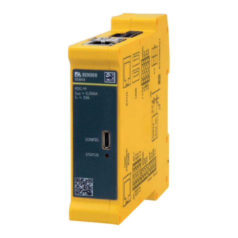
Bender
Bender CC613-H Series User manual
Bender
Bender ISOMETER isoPV425 with AGH420 User manual
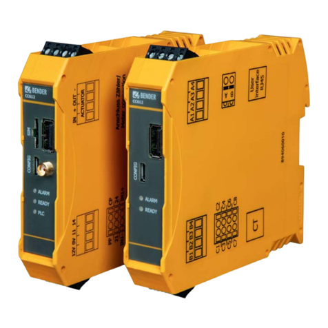
Bender
Bender CC612 User manual
Bender
Bender ICC1324 User manual

Bender
Bender CC612 User manual

Bender
Bender CC612 User manual

Bender
Bender CC612 EV User manual
Bender
Bender CC613 User manual

Bender
Bender CC613 User manual
Bender
Bender ISOMETER isoMIL425HV User manual

