Avago HEDS-8937 User manual

HEDS-8937
AEAT-6600-T16 Magnetic Encoder Programmer Kit
User Manual
This preliminary data is provided to assist you in the evaluation of product(s) currently under development. Until
Avago Technologies releases this product for general sales, Avago Technologies reserves the right to alter prices,
specications, features, capabilities, functions, release dates, and remove availability of the product(s) at anytime.
1. Introduction
Overview
This user manual describes the Avago HEDS-8937 pro-
grammer kit. The AEAT-6600-T16 magnetic encoder
programming kit features real-time monitoring and
programming of the 32-bit OTP memory within the
AEAT-6600-T16 magnetic encoder IC. The HEDS-8937
kit includes the IC interface hardware that is supported
by PC software.The IC interface hardware is a microcon-
troller system that links the AEAT-6600-T16 encoder to
the PC through a USB cable. This user manual describes
the hardware and PC software setup and gives instruc-
tions on PC software operation.
Features
Bus-powered USB device
On-board 6.5 V programming voltage
Auto-power o when the AEAT-6600-T16 is
removed from the programming socket
Read and write the 32-bit OTP memory
Real-time monitoring of SSI, PWM, ABI or UVW
outputs
Real-time monitoring of MAG_HI and MAG_LOW
signals
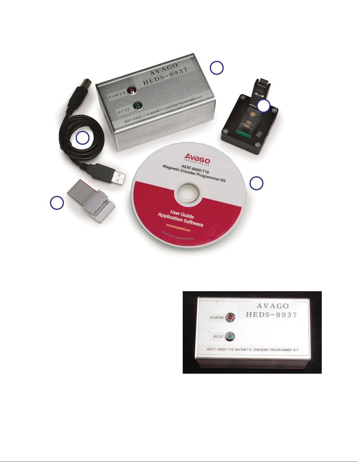
Figure 1. Inside the Programmer kit box
2. Hardware Component
Unpacking the Unit
The typical packing of the AEAT-6600-T16 magnetic
encoder programming kit is shown in Figure 1.
The kit contains:
1. USB cable
2. AEAT-6600-T16 magnetic encoder programmer
3. IC adapter socket
4. 16-pin ribbon cable
5. Installation CD

2
The programmer kit has ve parts as shown in Figure 2.
5
4
3
2
1
Figure 2. Components of the programmer kit
The USB cable (5) connects a PC USB port to the program-
mer (1).
Figure 3 shows the AEAT-6600-T16 programmer. The
red LED will light up when the programmer is powered
by connecting the programmer kit to the PC via the USB
cable. The green LED will blink when there is communi-
cation between the PC and encoder. The programmer’s
current consumption is less than 200 mA. The program-
mer incorporates a 100 mA current limiting circuit to
the IC adapter socket. If the current consumption for the
encoder being programmed or monitored exceeds 100
mA, the programmer will turn o the power supply to the
encoder. Figure 3. HEDS-8937 programmer top cover

3
Figure 4. Programming connector: 16-pin rectangular header connects to the IC adapter socket
The pin functions of the programming connector are
shown in Table 1.
Table 1. Programming connector pin functions
PIN Name Function
PIN 1 A, U Digital Input
PIN 2 B, V Digital Input
PIN 3 I, W Digital Input
PIN 4 MAG_HI Digital Input
PIN 5 MAG_LOW Digital Input
PIN 6 GND, GNDA IC Ground
PIN 7 ALIGN Digital Output
PIN 8 PWM Digital Input
PIN 9 VDD IC Supply
PIN 10 VDD_F Analog Input
(IC regulator output measurement)
PIN 11 PWRDOWN Digital Output
PIN 12 VPP IC Programming Voltage
PIN 13 PROG Digital Output
PIN 14 NCS Digital Output
PIN 15 CLK Digital Output
PIN 16 DO / DI Digital Output / Input
* All logic signals are 3.3 V TTL level signals
The 16-pin ribbon cable connects the programmer kit and
the IC adapter via the programming connector.
Figure 5 shows the IC adapter socket.
Figure 5. The IC adapter socket has a red dot that indicates pin 1 of the AEAT-
6600-T16 encoder
Pin 1
Triangle mark on connector body
15131197531
161412108642

4
3. Software Installation
The installation CD contains this user manual and the programmer application software. To install the application
software, browse to the software folder ‘Avago Magnetic Programmer’ and double-click the ‘Setup.exe’ icon in the
folder. The installation will run automatically. Figures 6, 7 and 8 illustrate the software installation.
Figure 6. Software installation startup screen. Click OK to start the installation.
Figure 7. Installation folder selection screen. Click ‘Change Directory’ to change the default installation folder.
Click the installation icon to continue.
Click Icon to install to the specied directory

5
Figure 8. Click 'Continue' to add the software under the default program group
The installation process will continue after the step shown in Figure 8, and nally a‘Setup successful’pop-up message
will indicate completion of the installation.
Locate the software by selecting: Start > All Program > Avago > Avago HEDS-8937 Application Kit (by default) or
other Start Group specied in the step shown in Figure 8.
To uninstall the software, open the Window’s Control Panel. Run ‘Add or Remove Program’ and locate ‘Avago
HEDS-8937 Application Kit’. Click 'Change / Remove", and follow the screen instructions to remove the software.

6
4. Software Application
4.1 OTP Programming
To run the application software, point to: Start > All Program > Avago > Avago HEDS-8937 Application Kit. After
selecting the software, the screen in Figure 9 will appear.
The software has three tabs: OTP Programming, Zero Position Programming and IC Monitoring. OTP programming
allows programming the OTP memory and zero position programming denes the zero position. The IC monitoring
tab displays the current encoder measurement.
Figure 9 shows the OTP programming tab. In the OTP programming tab, the software guides the OTP programming
step-by-step. When the ‘Detect IC’ button is clicked on the OTP programming tab, the software will locate the pro-
grammer and check for the presence of the AEAT-6600-T16 encoder.
Figure 9. OTP programming tab
Press this button to link the
software to the programmer.
OTP register values are available once encoder IC
presence is detected. The current SSI reading and
equivalent mechanical degree reading will also be
shown here.
Select OTP programming, Zero Position
Programming and IC Monitoring.

7
4.2 IC Detected
After the ‘Detect IC’ button is clicked and IC presence is detected, the screen in Figure 10 appears.
Figure 10. OTP memory conguration
Select either one of the
programming modes

8
The contents of the OTP memory are displayed in the‘Conguration Bit in OTP’frame. The indicated OTP memory is in
binary followed by the equivalent hexadecimal value.The symbol‘/’separates the binary and hexadecimal values. The
SSI ABS measurement is the position value captured when the ‘Detect IC’ button is clicked. ‘Mech Degree’ indicates
the equivalent mechanical angle calculated from the SSI ABS value.
If the encoder is detected, the ‘Select Programming Method’ frame appears. Select one of the output modes. This
selection enables the OTP conguration registers to be congured.
If ‘Absolute Output Only” is selected, only the ‘Absolute Resolution Setting’, ‘PWM Period Selection’, ‘PWM Output
Enable’, ‘Output Direction Invert’ and ‘Speed Mode’ selection options are enabled. The ‘Write OTP’ button will be
visible as well.
Figure 11. Absolute output only setting

9
Figure 13. Incremental output only setting
If ‘Incremental Output Only’ is selected, the ‘UVW Pole Pair Setting’ / ‘Index Pulse Width’, ‘Incremental Resolution
Setting’, ‘Zero Position Setting’, ‘Index Output logic’, ‘Incremental Mode’ and ‘Incremental Output Enable’ selection
options are enabled. The ‘Write OTP’ button will be visible as well.
Figure 12.Pop up message for mandatory incremental setting when selecting 16-bit for absolute.

10
If ‘Both Absolute and Incremental Output’ is selected, all the OTP conguration settings will be enabled (except the
Zero Position Setting). A pop-up message box, as shown in Figure 14 will appear.
Figure 14. Pop up message for mandatory incremental setting when selecting 16-bit for absolute.
Figure 15. Programming OTP memory
Click button to program
settings to OTP memory

11
After the conguration setting is complete, click the ‘Write OTP’ button to start OTP programming. The software will
compile the data to write to the OTP memory. A conrmation pop-up message box shows the data to be written to
the OTP memory, as shown in Figure 16. Click either the ‘Yes’ button to proceed with the programming or the ‘No’
button if reconguration is needed.
Figure 16. Pop-up conrmation message that appears before OTP programming starts
As shown in Figure 17 if the programming is successful, a pop-up ‘OTP Programming Pass’ message box summarizes
the selected values and the programmed values.
Figure 17. Programming result

12
If more than one encoder must be programmed with the same settings, key in the setting only once and click the
“Save Conguration File”button to save the encoder settings. Select“Read From File”to recall the IC settings and then
click the “Write OTP” button.
Figure 18. Save encoder settings to a le and read settings through the 'Read From File' feature

13
For zero position programming, select the centre tab ‘Zero Position Programming’and the ‘Zero Oset’ frame will be
enabled. Either the raw Hex code value for writing to OTP memory or the mechanical angle value can be entered. As
shown in Figure 19, once the setting is completed, click the ‘Write Zero Position Oset’ button to program the oset
value to the OTP registers.
Figure 19. Programming the zero position
Trigger Zero Position
Programming

14
After programming completes, as shown in Figure 21, the pop-up ‘Zero Oset PROGRAMMING PASS’ message box
is displayed.
Figure 21. Programming result pop-up message
A conrmation pop-up message box, shown in Figure 20, will appear before programming begins. When the ‘Yes’
button is clicked, the programming will start.
Figure 20. Programming conrmation pop-up message

15
4.5 AEAT-6600-T16 Encoder Monitoring
The monitoring tab displays the real-time output of the AEAT-6600-T16, as shown in Figure 22. The software captures
the position measurement at a 12 samples per second rate (update rate may slightly vary depending on the PC). The
monitoring software begins automatically when the IC monitoring tab is selected, provided the programmer and
encoder is present. If the programmer or encoder is not present, IC monitoring will be disabled and the active tab will
automatically switch back to the OTP programming tab.
Figure 22. AEAT-6600-T16 real-time status monitoring

16
5. Production In-circuit Programming
The programming kit performs in-circuit OTP programming of the AEAT-6600-T16 encoder mounted on a target
board. To perform in-circuit programming, connect the lines shown in Table 2 to the 16-pin programming header of
the target system.
Table 2. Pins required for in-circuit programming
MAG_HI / OTP_ERR (3)
MAG_LO / OTP_STAT (3)
PWRDOWN (3)
PROG (3)
NCS (3)
CLK (3)
DO/DI (3)
VDD_F (3)
VDD (Optional)(1)
VPP (2)
GND
Refer to Table 1 for the pinout of the 16-pin rectangular header.
Once a connection is made, follow instructions described in Section 4 to perform OTP programming and zero-posi-
tion programming. The IC Monitoring feature can also be used but monitoring of PWM and ABI/UVW will be disabled.
Important notes:
1. VDD is not required if the on-board IC is powered by the target system.
2. During OTP programming, the target system/host, such as micro-controller, should turn o and the programming
kit will supply 6.5 V to the VPP pin and 5 V / 3.3 V to the VDD pin.
3. As pins may be shared between the programmer kit and the target host device, such as microcontroller, make sure
that these pins are not driven by the host device. All pins should be kept in a high-impedance state (Hi-Z).
6. Troubleshooting Guide
6.1 Programmer Not Found
If the programmer is not found, the following message will be displayed.
Figure 23. Programmer not found message
Check the connection and ensure that the POWER LED on the programmer kit is on. If the Power LED is o, the cause
is potentially due to hardware. Please contact your distributor for repair as there are no user serviceable parts in the
programmer.

17
Figure 24. IC not present message
There are three possibilities for this condition:
1. The IC adapter socket is not connected to the programmer (via the programming connector). Connect the IC
adapter socket to the programmer using the provided 16-pin ribbon cable.
2. Wrong orientation of the IC placed in the IC adapter socket. Check and ensure pin 1 of the encoder IC is aligned
with the RED dot on the bottom side of the IC socket.
3. The encoder has not been loaded in the IC adapter socket or the loaded encoder IC is faulty. Replace with a new IC
and try again.
Figure 25. Ensure pin 1 of the encoder IC is aligned with the red dot
6.2 IC Not Present
If the AEAT-6600-T16 IC is not present in the programmer, the following message will be displayed.

18
7. Updating the HEDS-8937 Application Kit Firmware
Note: To get the up to date both i-Stone iBootloader downloader and HEDS-8937 Application Software please
download from Avago product webpage: (http://www.avagotech.com/pages/en/motion_control_encoder_
products/) under part number HEDS-8937
To update the HEDS-8937’s rmware you will need:
1. A PC running a Microsoft Windows based operating system
2. The i-Stone iBootloader downloader PC software executable
3. A new Avago HEDS-8937 rmware Hex le (*.hex)
7.1 Firmware Update Procedure
1. Start the i-Stone iBootloader downloader software. The following screen will be displayed.

19
2. Connect an Avago HEDS-8937 application kit to the PC using one of the USB ports. The downloader software will
detect the application kit as shown below.
3. Click the “Boot Mode”button to switch the application kit to bootloader mode.
4. Once successful, the downloader software will show “Device attached” in the status box as below.

20
5. Click the “Open Hex File” button and a le selection dialog box will be displayed. Browse and select the new HEX
le provided. After the HEX le is loaded, the “Program/Verify” button will be enabled.
6. Click the“Program/Verify”button to start the rmware update process. Once started, the downloader software will
perform an erase, program and verify cycle as shown below.
This manual suits for next models
2
Table of contents
Other Avago Motherboard manuals