Avantco 178GDICE24FB User manual

Ice Merchandisers
Service Manual
www.AvantcoRefrigeration.com
11/2022
This manual is for a certified service technician and should not be used by those who are not properly trained.
This manual cannot cover all possible conditions that may occur and is not intended to be all encompassing.
You should read this manual in its entirety and the specific repair you wish to do prior to starting the repair.
This will allow you to determine if you have the correct tools, instruments, and skills to perform the procedure.
#178GDICE24FB 31" Black Indoor Glass Door Ice Merchandiser
#178GDICE24FW 31" White Indoor Glass Door Ice Merchandiser
Note:
Models:
Ice Merchandisers
#178GDICE49FB 53" Black Indoor Glass Door Ice Merchandiser
#178GDICE49FW 53" White Indoor Glass Door Ice Merchandiser
178GDICE49FB

2
www.AvantcoRefrigeration.com
Ice Merchandisers
Service Manual
Troubleshooting..................................................................................................................................... 3
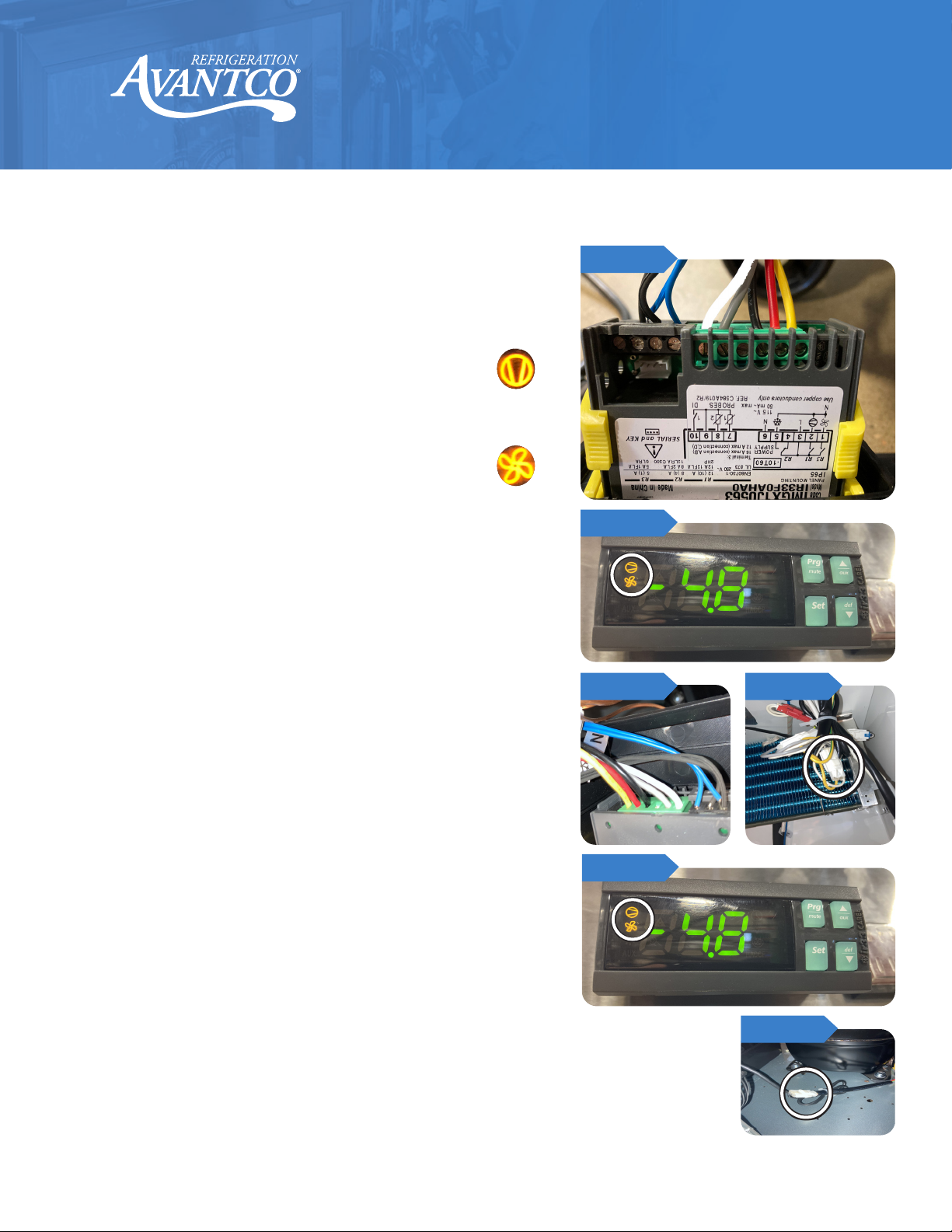
Temperature Controller Settings....................................................................................................... 5
Part Testing ............................................................................................................................................. 7
Controller Testing.................................................................................................................................. 7
Evaporator Fan Motor Testing ........................................................................................................... 7
Condenser Fan Motor Testing ........................................................................................................... 7
Compressor and Capacitor Testing.................................................................................................. 8
Part Repair............................................................................................................................................... 9
Temperature Controller ....................................................................................................................... 9
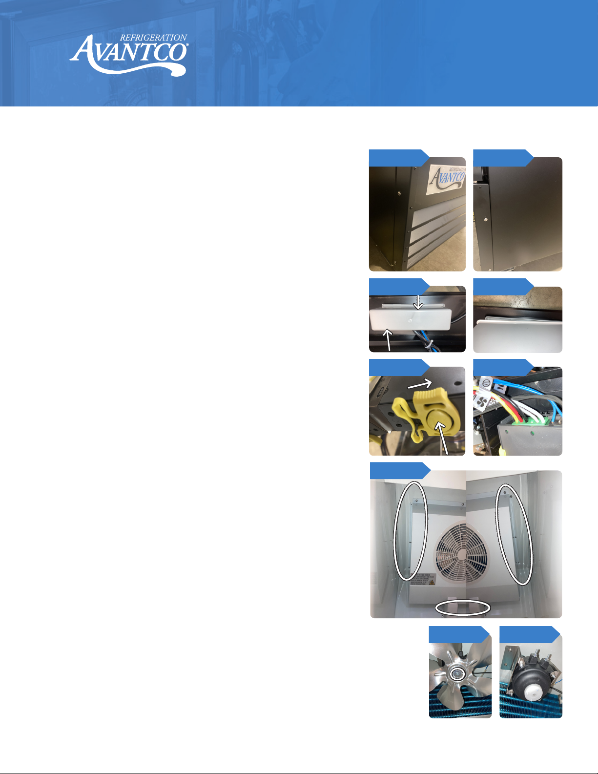
Evaporator Parts .................................................................................................................................... 9
Evaporator fan blade............................................................................................................................ 9
Evaporator fan motor ........................................................................................................................... 9
Evaporator Coil ...................................................................................................................................... 10
Cabinet temperature probe................................................................................................................ 10
Evaporator temperature probe.......................................................................................................... 10
Defrost element..................................................................................................................................... 10
Condenser Parts.................................................................................................................................... 11
Condenser coil....................................................................................................................................... 11
Condenser fan blade............................................................................................................................ 12
Condenser fan cover............................................................................................................................ 12
Condenser fan motor ........................................................................................................................... 12
Starting components ............................................................................................................................ 12
Compressor ............................................................................................................................................ 12
Filter drier ................................................................................................................................................ 12
Wire Diagram.......................................................................................................................................... 13
178GDIC24FB/W................................................................................................................. 13
178GDICE49FB/W .............................................................................................................. 14
Parts Diagram......................................................................................................................................... 15
178GDICE24FB/W .............................................................................................................. 15
178GDICE49FB/W .............................................................................................................. 17
Table of Contents

3
www.AvantcoRefrigeration.com
Ice Merchandisers
Service Manual
Troubleshooting
Problem Possible Solution
Unit will not turn on
Ensure that unit is plugged in
Ensure the outlet is correct size, dedicated and has power to it
Check controller
Check compressor
Unit not getting to set
temperature
Ensure door is properly sealed
Check door gasket for rips, tears, cut, etc.
Ensure set temperature is correct
Ensure default parameters are correct on the controller
Check evaporator coil for ice or frost buildup
Ensure condenser coil is clean
Check door switch is functioning
Check if evaporator fan is operating
Check if condenser fan is operating
Check compressor operation
Check cabinet temperature sensor
Unit not holding set
temperature
Check door gasket is free of rips, tears, cuts, etc.
Ensure cabinet inside has good air circulation and is not blocking evaporator fan
Ensure parameters are correct on controller
Ensure condenser coil is clean
Ensure evaporator coil is clean and not frozen
Check door switch is functioning
Check if evaporator fan is operating
Check if condenser fan is operating
Check cabinet temperature sensor
Ensure defrost heating element is not on
Check compressor operation
Ice coming from inside
cabinet drain/pan
Check parameters are correct on controller
Check drain pan hose for clog
Check defrost heating element
Check evaporator fan and motor
Check drain hose heater

4
www.AvantcoRefrigeration.com
Ice Merchandisers
Service Manual
Problem Possible Solution
Compressor is not running
Ensure unit is plugged in and turned on
Ensure controller parameters are correct
Check controller is telling compressor to run
Check start components
Check compressor for power
Unit turns o before
reaching set temperature
Ensure proper voltage on the plug
Ensure controller settings are correct
Ensure condenser coil is clean
Ensure controller is sending power to compressor
Check cabinet temperature sensor
Check compressor for power
Inside cabinet fan not
working
Check parameters are correct on controller
Check controller is telling evaporator fan to run
Check door switch
Check evaporator fan motor
Water is coming from
under the unit
Check drain hose is inside condensate pan
Check parameters are correct on controller
Check defrost element
Check drain hose for clogs
E0 error showing on
controller
Ensure wiring into controller is secure
Check cabinet temperature sensor
E1 error showing on
controller
Ensure wiring into controller is secure
Check evaporator temperature sensor
Troubleshooting
(Continued)

5
www.AvantcoRefrigeration.com
Ice Merchandisers
Service Manual
Temperature Controller Settings
1. To access settings on temperature controller, hold the "Prg/mute" button and "Set" button
down simultaneously until the display flashes with a zero.
2. Push the "up arrow/aux" button until the display shows 22.
3. Press the "Set" button to enter the programming mode of the controller.
4. To save any changes that are made, press and hold the "Prg/mute" button until the set
point temperature shows on the controller display.
5. Use "Up" and "Down" arrows to change values for each option.
6. Press the "Set" button to keep the option.
Code Description Options Default
Unit of measure of temperature display 0 = °C
1 = °F 1
Evaporator fan runs during defrost mode 0 = Fan runs
1 = Fan does not run 1
Evaporator fan runs with compressor o 0 = Reference F0 option
1 = Fan always o when compressor o 1
Evaporator fan activation temperature
(Only functions if F0 = 1 or 2) -5° - 200° 41°
Fig. 1

6
www.AvantcoRefrigeration.com
Ice Merchandisers
Service Manual
Code Description Options Default
Evaporator fan management
0 = Fan is always running
1 = Fan runs based on dierence of cabinet
probe temperature and evaporator probe
temperature
2 = Fan runs based on evaporator probe
temperature
2
Dripping time after defrost, evaporator fan is o 0 to 15 min. 2 min.
Maximum defrost duration/length 1 - 250 min. 30 min.
Temperature that defrost ends
(Temperature taken from defrost probe) -5° - 200° 58°
Maximum time between consecutive defrost cycles 0 = Unit will never go into defrost
1-250 = Time in hours 3 hours
Compressor, fan, and auxiliary start delay when unit is turned
on 0 - 15 min. 2 min.
Maximum set point for temperature for when in continuous
cycle mode r1 to 200° 10°
Minimum set point for temperature for when in continuous
cycle mode -50° - r2 -7.6°
Temperature dierential from set point (Tells compressor when
to turn back on after reaching set temperature) 0.1° - 20° 2.0°
Set point for when in continuous cycle mode r1 - r2 18°
Probe 2 calibration
(Evaporator temperature) -20° - 20° 0°
Probe 1 calibration
(Cabinet temperature) -20° - 20° 0°
Temperature Controller Settings
(Continued)

7
www.AvantcoRefrigeration.com
Ice Merchandisers
Service Manual
Part Testing
Evaporator Fan Motor Testing
1. Ensure controller is calling for evaporator fan to run
(Fig. 3) then:
2. Check for 120 volts between yellow (fan) and white
(L) wires, fan ON only. (Fig. 4)
3. Check for 0.3 amps+/- 10% at yellow wire at rear of
controller. (Fig. 4)
4. If tests above fail, replace fan motor.
Condenser Fan Motor Testing
1. Ensure controller is calling for compressor to run
(Fig. 6) then:
2. Check for 120 volts at fan plug between the blue
and brown wires.
3. Check for 0.4 amps +/- 10% on blue wire.
(Fig. 7)
4. If tests above fail, replace fan motor.
Controller Testing
1. Check for 120 volts between black (L) and white (N)
wires, main power.
2. Check for 120 volts between red (compressor) and
white (L) wires, compressor ON only.
3. Check for 120 volts between gray (defrost) and
white (L) wires, defrost mode only.
4. Check for 120 volts between yellow (fan) and white
(L) wires, fan ON only.
Fig. 2
Fig. 3
Fig. 4 Fig. 5
Fig. 6
Fig. 7

8
www.AvantcoRefrigeration.com
Ice Merchandisers
Service Manual
Part Testing
Compressor and Capacitor Testing
With the unit 'ON' and controller calling for the
compressor to run, check amperage on 'red' wire coming
from the controller, see table below for values +/- 10%
Disconnect wiring from compressor, check resistance
from common to run and start windings. Resistance
should be found (Run to Start = (Runs to Common) + (Start
to Common))
Temperature will change resistance OHM valves
Check windings are not connected to ground by
checking for Ohms from each pin to the shell of the
compressor (Paint must be removed from case when
checking for grounding)
Visually check capacitor for any deformations or leaking
oil like fluids, replace if any is found
Discharge capacitor prior to testing, use a 20,000 ohm, 2
watt carbon resistor, caution resistor will be HOT during
discharge
Capacitor micro-farads = µF +/- 5%, replace if not within
range
Model # Max Load
Amps
Locked Rotor
Amps (LRA)
178GDICE24FB/W 7.6 Amps 39.7 Amps
178GDICE49FB/W 10.6 Amps 55.2 Amps
Fig. 9
Fig. 10
Fig. 11
Fig. 8

9
www.AvantcoRefrigeration.com
Ice Merchandisers
Service Manual
Part Repair
Temperature Controller
1. Ensure unit is turned o and unplugged.
2. Remove Phillips screws holding the front
condenser grill to the unit. (Fig. 12 & 13)
3. Remove the controls cover by squeezing both long
sides and lifting it away from the condenser grill.
(Fig. 14 & 15)
4. Push in on yellow button and slide yellow clamp
towards the rear on the controller. (Fig. 16)
5. Pull controller through mounting plate and remove
wiring (green and black connectors) Note locations
for new controller. (Fig. 17)
6. Installation is reverse of removal.
Evaporator Parts
1. Ensure unit is turned o and unplugged.
2. Open door of the unit and remove shelving as
required and rear shelf clips are needed.
3. Remove Phillips screws holding evaporator
drain cover and main panel in place to expose
evaporator parts. (Fig. 18)
Evaporator fan blade
4. Remove Phillips screw holding fan blade onto fan
motor. Note blade dish and direction. (Fig. 19)
Evaporator fan motor
5. Remove Phillips screws holding evaporator fan
motor to inside top of unit. (Fig. 20)
6. Remove screws holding mounting brackets to fan
motor with a Phillips screw driver and 7mm wrench.
Install brackets on new replacement fan. (Fig. 21)
7. Disconnect wiring from unit. (Fig. 22)
Fig. 12
Fig. 16 Fig. 17
Fig. 14 Fig. 15
Fig. 13
Fig. 18
Fig. 19 Fig. 20

10
www.AvantcoRefrigeration.com
Ice Merchandisers
Service Manual
Evaporator Coil
Before removing evaporator coil, ensure all refrigerant has
been removed from the system following state, federal,
local and EPA regulations regarding refrigeration. Follow
all guidelines and safety procedures when working with a
flammable refrigerant. All connections where refrigerant
travels must be checked for leaks after connections are
brazed in place.
1. Remove capillary tube and suction line from evaporator
coil. Do not crush capillary tube. (Fig. 23)
2. Remove Phillips screws holding evaporator coil to inside
ceiling of the unit. (Fig. 23)
Cabinet temperature probe
3. Disconnect blue probe wiring from rear of controller.
(Fig. 24)
4. Open front door of unit and remove Phillips screw
holding probe cage in place. (Fig. 25)
5. Pry open probe cage to remove probe.
6. Use old probe wires to fish new probe wires through
the unit and back to the controller.
7. Reconnect to controller and secure new probe in cage
and mount to inside ceiling panel.
Evaporator temperature probe
8. Disconnect black wiring from rear of controller. (Fig. 24)
9. Open front door of unit locate probe inside evaporator
coil. (Fig. 26)
10. Use old probe wires to fish new probe wires through
the unit and back to the controller.
11. Connect new wires to controller and secure new probe
in evaporator coil.
Defrost element
12. Remove drain pan and blanket heater by removing
Phillips screws holding drain pan to evaporator. (Fig. 27)
Continued on next page
Part Repair
Fig. 23
Fig. 26
Fig. 24
Fig. 25
Fig. 27
Fig. 21 Fig. 22

11
www.AvantcoRefrigeration.com
Ice Merchandisers
Service Manual
Part Repair
13. Disconnect wiring plug inside of unit. (Fig. 28)
14. Remove spring wire clamps holding element to
evaporator coil. (Fig. 29)
15. Installation is reverse of removal.
1. Ensure unit is turned o and unplugged.
2. Remove front condenser grill by removing
Phillips head screws holding grill in place. (Fig.
30 & 31)
3. Remove Phillips screws from condenser tray
clamp. (Fig. 32)
All EPA, federal and local guidelines need to
be followed when working with refrigeration.
Follow all guidelines and safety procedures
when working with a flammable refrigerant. All
connections where refrigerant travels must be
checked for leaks after connections a brazed in
place.
4. Pull condenser tray out to access the condenser
coil, condenser fan and compressor. Ensure
linesets do not get damaged during tray
removal.
Condenser coil
5. Remove condenser coil by cutting copper lines.
6. Remove 4 Phillips head screws holding coil
onto condenser tray. (Fig. 33)
Continued on next page
Condenser Parts
Fig. 28
Fig. 29
Fig. 30 Fig. 31
Fig. 32
Fig. 33

12
www.AvantcoRefrigeration.com
Ice Merchandisers
Service Manual
Part Repair
7. Remove fan motor, blade and cover from
condenser coil by removing 4 Phillips head screws.
(Fig. 34)
Condenser fan blade
8. Remove fan blade from fan motor by removing the
hex head bolt with a 7mm socket. DO NOT lose the
washer. Note fan blade dish and direction. (Fig. 35)
Condenser fan cover
9. Remove fan cover by removing 4 hex nuts with an
7mm socket. (Fig. 36)
Condenser fan motor
10. Unplug the fan motor from the unit wiring. (Fig. 37)
Starting components
11. Remove compressor wiring cover.
12. Removing wiring from compressor. Note wire
locations for new electronics.
13. Remove Phillips screws holding starting
components to condenser tray. (Fig. 38)
Compressor
14. Remove compressor by cutting the suction and
discharge lines.
15. Remove 4 mounting bolts from compressor legs
with a 10mm wrench. (Fig. 39)
Filter drier
16. Remove the filter by cutting the copper lines.
Ensure capillary tube is not damaged. (Fig. 40)
17. Remove from clamp by prying apart clamp clip on
compressor side of clamp. (Fig. 40)
18. Installation is reverse of removal.
19. Check all refrigerant lines, new and old, for leaks.
Fig. 38 Fig. 39
Fig. 34 Fig. 35
Fig. 36 Fig. 37
Fig. 40

13
www.AvantcoRefrigeration.com
Ice Merchandisers
Service Manual
Wire Diagram
178GDICE24FB/W

14
www.AvantcoRefrigeration.com
Ice Merchandisers
Service Manual
Wire Diagram
178GDICE49FB/W

15
www.AvantcoRefrigeration.com
Ice Merchandisers
Service Manual
Parts Diagram
178GDICE24FB/W

16
www.AvantcoRefrigeration.com
Ice Merchandisers
Service Manual
Item # Description Part # Item # Description Part #
5 Power switch 17810365 32 Evaporator fan motor 17816212
6 4" caster, no brake 17819301 33 Evaporator fan blade 17818098
7 4" caster, with brake 17816412 35 Evaporator fan cover Call manufacturer
9 Door switch 17817409 37 Start components
11 Door gasket 178GSKT12549 38 Compressor 178NLE10CN
14 Door - Black 17811466 39 Condenser fan motor 17816212
14 Door - White 17885572 40 Condenser fan cover Call manufacturer
16 Shelf - bottom 17813233 41 Condenser fan blade 17818098
17 Shelf - back 17813232 49 Hinge - bottom 17810312
18 Light box cover 17821683C 50 LED power supply 17815994
21 LED bulb - light 17818244 51 Controller 17819471 or 17819947
22 Hinge - upper 17818244 52 Light switch 17810364
24 LED bulb - cabinet 17818242 54 Filter drier 970C032S
25 Evaporator coil 55 Condenser coil 17810649HC
26 Defrost element Cabinet temperature sensor
27 Drain line heater 17817223 Evaporator temperature
sensor
29 Drain pan heater Capillary tube
Parts Diagram
178GDICE24FB/W

17
www.AvantcoRefrigeration.com
Ice Merchandisers
Service Manual
Parts Diagram
178GDICE49FB/W

18
www.AvantcoRefrigeration.com
Ice Merchandisers
Service Manual
Item # Description Part # Item # Description Part #
4 4" caster, with brake 17816412 36 Door - right (Black) 17816560
5 4" caster, no brake 17819301 36 Door - right (White) 178154548
13 Controller 17819471 or 17819947 37 Hinge - upper right 178H152349TR
14 Light switch 17810364 38 Shelf - bottom 17813233
15 Power switch 17810365 39 Shelf - back 17813232
16 Door switch 17817409 40 LED bulb - cabinet 17818246
17 Hinge - bottom 17810312 43 LED power supply 17815994
21 Condenser coil 17815157HC 46 Drain pan heater 17815645HC
22 Defrost element 17816974 47 Light box cover 17821683C
23 Condenser fan
cover
Call manufacturer 49 LED bulb - light box 17818242
24 Condenser fan
blade
17811089 50 Evaporator fan cover Call manufacturer
25 Condenser fan
motor
17816212 52 Evaporator fan blade 17818098
26 Start components 53 Evaporator fan motor 17816212
27 Compressor 17817445 54 Drain line heater 17817223
29 Filter drier 970C032S 56 Evaporator coil 17810622
33 Door - left (Black) 17816560 Cabinet temperature sensor
33 Door - left (White) 17816562 Evaporator temperature
sensor
34 Hinge - upper left 17818742 Capillary tube
35 Door gasket 178GSKT17556
Parts Diagram
178GDICE49FB/W
This manual suits for next models
3
Table of contents
Other Avantco Merchandiser manuals
Popular Merchandiser manuals by other brands

True
True GDM-7 Specifications

Hussmann
Hussmann NEBBDT Installation & service manual

Structural Concepts
Structural Concepts Oasis CO2739R Installation and operating manual

FRIGOGLASS
FRIGOGLASS Flex 35 HC user manual

Hussmann
Hussmann HEDN Technical data sheet

Alto-Shaam
Alto-Shaam ITM2-72/STD Installation operation & maintenance