AVC Quingo Vitess 2 User manual

1
Keep this Manual in a safe place
This document contains the information
required to familiarise yourself with your vehicle
Complete all the information within this document
If any information is not clear please contact your service provider immediately
This document must remain with the vehicle throughout its life
Product Model Number…………………………………………..
Serial Number……………………………………………………….
Date of Purchase…………………………………………………..
NOTICE
This vehicle was supplied by.
This product is manufactured by: AVC LTD,
Sovereign Court, 230 Upper Fifth Street, Central Milton Keynes, Bucks MK9 2HR England.
Owners Manual and Service Record
Quingo Vitess 2

2
Contents
NOTICE
The contents of this document regarding photographs and text may change because of specification
upgrades. AVC Ltd retains the right to change specification of its products without prior notice.
Subject Page No.
Introduction 1
Contents 2
Safety Information 3
Intended use of the vehicle, Intended user 4
EMI Information 5
Display and Controls SAFETY INFORMATION 6-8
Emergency Brake SAFETY INFORMATION 9
Free Wheel Device SAFETY INFORMATION 10
Safety Display Warning SAFETY INFORMATION 11
General Note on Adjustments 12
Seat Adjustments 13-14
Backrest, Footplates & Seatbelt Adjustments 15
Tiller Features 16
Seat Height Adjustment & Front Basket Removal 17
Transporting the Scooter 18
Battery charging, general care 19-20
Optional Full Weather Canopy/Beacon 21
Daily Check List & Safety Information SAFETY INFORMATION 22
Driving your Scooter & Storage SAFETY INFORMATION 23-24
Troubleshooting Guide 25
Scooter Fault Indicators 26
Common Questions 27
Reporting a Fault and Servicing Information 28
Service Check List QUINGO SERVICE ENGINEER ONLY 29
Service Log QUINGO SERVICE ENGINEER ONLY 30
Technical Information Regarding EMI 31
Guarantee & Warranty, explains what is covered under your warranty 32
Technical specification 33

3
Safety Information
Read this manual thoroughly before driving or operating the vehicle.
Every mobility scooter operates differently. Do not assume they are the same.
If you have any doubt about the content of this manual phone your service provider
immediately. Read the instructions contained within this document, they apply to the
Quingo Vitess 2. The photographs in this document depict the Quingo Vitess, Quingo
Vitess 2 and Quingo Toura
Maintain the vehicle correctly and ensure a Quingo trained technician services it regularly.
© 2015 Advanced Vehicle Concepts Ltd.
No liability is assumed with respect to the use of any information contained in this publication. While every
precaution has been taken in the preparation of this publication Advanced Vehicle Concepts Ltd. assumes
no responsibility for errors or omissions nor is any liability assumed for damages resulting from the use of
information contained in this publication. This publication, as well as the operational details described herein,
is subject to change without notice.
Safety Notices
Within this manual there are important safety notices.
They are clearly marked on the appropriate pages.
Make sure that you understand these notices.
If any part is unclear phone your service provider.

4
Intended Use of the Scooter & Intended User
Intended Use of the Scooter
Designed solely for use by a disabled person (up to the maximum recommended weight)
who requires a mobility scooter with maximum versatility and a safe, comfortable seating
position with maximum manoeuvrability. This unit can be transported in the rear of a car
but weight and dimensions should be checked before purchase.
The vehicles have been classified according to EN 12184 as class B mobility product
(For indoor and outdoor areas). Speed, range, turning circle, safe climbing ability,
maximum obstacle height and permissible operating conditions can be found in "Technical
Specifications". All models are fitted with a suitable lighting system for use on public
roads.
The scooters are not intended to run in deep water (over 5cm) or muddy areas, but can be
run on hard ground. Avoid sandy or gravel areas as this can seriously affect the range.
These scooters are not intended as off-road vehicles.
Use by Another Person or Insurant
The vehicle can be used by an additional person other than the owner/driver.
Before usage the following checks should be carried out:
Is the seat height comfortable?
Is the angle of footrests correct?
Are the armrests adjusted correctly?
Is the seat adjusted forward or rearward to suit the driver?
Have the controls been explained?
Has the free wheel device been demonstrated?
Have you been shown how to operate the handlebar emergency brake?
Have you had a demonstration of the capabilities of the product?
Have you been shown the charging procedure?
Has the driver been given a copy of the handbook?
Before the additional driver is allowed on their own, please check they are capable, both
physically and mentally, to drive the vehicle safely.

5
EMI Information
Information regarding Electromagnetic Interference (EMI)
This section contains information on the possible effects of electromagnetic interference to
your vehicle.
EMI refers to the effects that electromagnetic energy might have on the control systems of
your vehicle. The interference could cause the brakes to release, the vehicle to move by
itself or damage the electronics.
There are broadly three types of sources of electromagnetic energy:
1. Hand Held, Short Range Portable Transceivers. Examples include: CB radios,
walkie-talkies, security, fire and police transceivers, mobile phones and other
devices that transmit a signal even when not in use.
2. Medium Range Mobile Transceivers. Examples include: police, fire, ambulance
and taxi transceivers.
3. Long Range Transmitters and Receivers. Examples include: radio and television
towers and amateur (HAM) radios.
There is an immunity level that has to be met by law and your scooter has been tested to
the required level. For a full technical explanation see Page 31 in this document.
WARNING
Even though your vehicle meets the requirements, it is recommended that you follow
certain precautions.
1. Do not operate hand held transceivers such as CB radios or mobile phones while
the vehicle is switched on.
2. Be aware of transmitter masts, such as television and radio stations. Avoid
getting close to them.
If your vehicle starts to operate by itself switch it off and call your service provider.
Report all faults of this type.
Life Expectancy of the Product
The life expectancy of the product to be 5 years. This is provided that it is used in strict
accordance with the intended use as set out in this document and all service and
maintenance requirements are carried out as recommended.
The estimated life expectancy may be exceeded if the product is used carefully and
properly maintained. It can also be considerably reduced by extreme or incorrect use.
Although we estimate the life expectancy for this product, it does not constitute an
additional warranty.

6
Display & Controls
Your Quingo has many features that other scooters do not have. It’s important that you
understand all the functions.
Switch on the ignition and the display will light up.
The information you need to know for now is as follows:
Temperature Gauge: On the top right hand side of the display in the photograph below
is the number 9c. This is the temperature gauge and it will show the current outside
temperature. Your engineer can set this display in Celcius (as shown below) or in
Fahrenheit.
Battery Gauge: When fully charged, the battery gauge has 8 bars and these bars will
disappear when your scooter is in use. Starting from right to left the battery is running
down from ‘F’ (Full) to ‘E’ (Empty). Do not let the bars drop below 4 before returning
home and recharging.
Note that battery indicators provide a guide only and are not 100% accurate.
The recommended way of reading the available charge in your scooter is to find a piece
of flat ground clear of obstacles. Switch the scooter to half speed and pull in the throttle
fully. Check the reading on the display, this is your battery state.
Speedometer: This will display your current speed. Your engineer can set this display in
‘kph’ (kilometres per hour as shown below) or in ‘mph’ (miles per hour).
IMPORTANT NOTES ON THE SPEEDOMETER
The Speedometer is a guide to the speed you are travelling at.
The speed shown has a +. - 15% variance compared to actual speed.
The maximum speed you can travel at will be affected by certain conditions such as:
- TEMPERATURE
- WEIGHT OF THE DRIVER
- TYRE PRESSURES
- TERRAIN
Odometer: This displays the total distance your Quingo has covered. Your engineer can
set this display in ‘km’ (kilometres as shown below) or in ‘miles’.
IMPORTANT NOTES ON THE ODOMETER
There are many factors that can affect the range of an electric vehicle and these are
detailed in the:
- BATTERY CHARGING
- TROUBLE SHOOTING GUIDE
- COMMON QUESTIONS
Sections of the handbook.
Temperature
Odometer
Speedometer
Battery Gauge

7
Display & Controls
When buttons are pressed on the dashboard, in most cases an icon will illuminate on
the display. Below we show the basic functions of the switches and what is displayed.
There are also other features that can be displayed.
Please note that the separate displays in this photograph show different indications.
The Horn
Notice that you have 2 horn buttons to allow for both left and right-handed users. In
this instance no additional icon is displayed.
Speed Control
This controls the top speed of your
scooter. Turn anti-clockwise to
decrease speed & clockwise to
increase speed.
Half Speed
When this button is depressed the top
speed will be halved. This feature is
normally used in a pedestrian area. In
some countries this is law.
Check with your local authority.
Horn
Horn
Right Indicator
Press for turning right and the
other side for left
Lights
Press and front & rear lamps
switch on
Hazard Lights
Press and the hazard warning
lamps switch on and the horn
will beep
Left
Indicator

8
Display & Controls
Handbrake: This is for emergency use only. In the unlikely event that the main braking
system should fail this can be used to slow the vehicle.
WARNING NOTICE!
The lever mechanism should be treated with care as it could become damaged if misused.
Carry out recommended checks. Do not pull both levers in at once. This will damage
the mechanism.
1. (Carry out daily) Before using the scooter check the mechanism for full and free
movement (see photograph below). With the ignition off and the key removed pull
the lever in fully on the right hand side then release. The lever should return
immediately to the normal position. Pull the left hand lever in fully then release. The
lever should return immediately to the normal position. If the lever does not return
immediately to the normal position (it sticks) contact your service provider
immediately and DO NOT ATTEMPT TO OPERATE THE SCOOTER.
2. Never lean or place your body weight on the levers. This will damage the
mechanism.
3. If you have a weather cover on the scooter, please take care when removing it
especially in the tiller area. Make sure the cover does not snag the levers.
4. Do not hang objects such as bags or attach dog leads to the handlebar or the lever
mechanism.
Checking for full and free movement
Remove ignition key
Levers shown in the normal Position
Pull Left
lever to go
backwards
Pull Right
lever to go
forward
Pull in fully
and release
Handbrake
Pull in fully
and release

9
Warning: If the ignition switch is turned off while the vehicle is at speed the vehicle will
come to an abrupt stop. If you are in a situation where you need to stop abruptly use the
emergency brake. Only switch off the ignition as a last resort.
Emergency Brake
A brief explanation of how the brakes work on your scooter.
Your scooter has 3 braking systems.
1. The emergency brake. This is situated on the tiller (See arrow below). This is a hand
operated brake to be used in an emergency only.
2. The electromagnetic brake or Automatic handbrake. When you move off this
releases automatically. When the scooter stops it engages automatically and stops
the scooter rolling forward or backward.
3. The regenerative brake. This works when you release the accelerator lever.
The faster you release the lever the faster the machine slows down. When it slows
down enough, the automatic brake engages.
10
Free Wheel Device
Important Safety Notice: The freewheel device allows the vehicle to be moved without
power. When the lever is moved upwards the automatic brakes are released. This
means there is no braking except for the emergency brake (Page 9). Follow these
instructions and if you are in any doubt contact the service provider immediately.
Points when using the freewheel device.
NEVER release the brake and sit on the scooter
NEVER release the brake on a slope. Only on flat ground
ALWAYS remove the ignition key
If you are unsteady on your feet do not attempt this manoeuvre
1. Make sure the scooter is on level ground
2. Remove the ignition key
3. Do not sit on the scooter at any time the vehicle is in free wheel
4. Release the lever (see photos)
5. Push the scooter to the area you require using the emergency brake (Page 9) to
control the speed
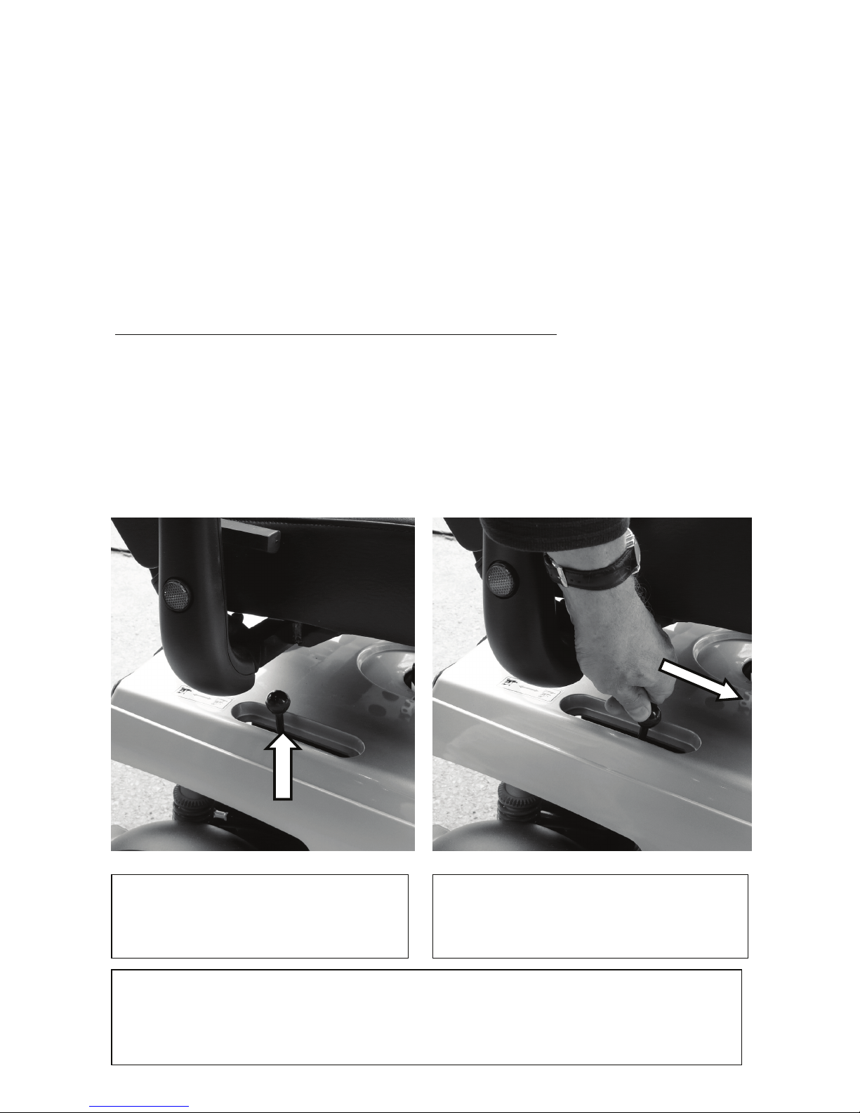
6. Lock the lever (see photos)
The freewheel release lever is situated
under the right hand side of the seat.
This is shown in the locked position.
To release, push forward. This may be
quite stiff to operate. The vehicle is now in
free wheel mode
When you have finished moving the scooter, pull the lever
back into the locked position immediately.

11
Safety Display Warning
If you do not lock the free wheel device and try to use the scooter you will see this on the
display:
The ‘spanner’ icon with the number 5.
The spanner means there is a fault and the number 5 means the free wheel is not locked.
The scooter will not drive. To clear the fault:
1. Turn the ignition off & get off the scooter immediately.
2. Lock the free wheel device as shown on page 10
3. Turn on the ignition and the spanner and number 5 will disappear
4. The scooter will now operate correctly.
Another common rider fault is pulling in the lever mechanism (Page 8) at the same time
when turning on the ignition. The scooter will see a fault and the spanner with the number
6 will show on the display. Simply release the lever for a few seconds and the scooter will
automatically reset.
You can now drive off.

12
General Note on Adjustments
Your Quingo is unique as it has many adjustment combinations.
The general rule is to keep the footrests as far forward as possible. Keep the seat as low
as possible and adjust the seat and tiller to suit. This places the weight forward, which aids
comfort to the rider and enhances stability especially when negotiating hills.
The Quingo Vitess 2 allows users to assume the correct seating position
(as shown in white dotted lines) Feet forward and forearms level with the tiller
Tiller
Slider
Armrest
Width
Armrest
Backrest
Seat Height
Revolving Seat
Footrest Angle
Footrest Angle
Footrest left & right

13
Seat Adjustments
The seating on your scooter can be adjusted to various positions for your comfort. The
service engineer will set these adjustments up for you but if you want to adjust it yourself
please see the below instructions. If you have a weak grip do not attempt these
adjustments.
REMOVE THE IGNITION KEY BEFORE ADJUSTING ANYTHING
To adjust the armrest height loosen the clamp and move the arm rest up or down to suit.
The armrests should always be in line with the handlebars.
Revolving Seat: The seat is able to revolve and lock every 45 degrees. This has 2
functions. The first is to allow easy access on and off the scooter. The second is to allow a
comfortable seating position when stationary, for example, when sitting in a café. To
operate (when seated) lift the lever and turn the seat to the desired position. When at that
position release the lever and turn the seat until you hear it lock.
Important: When returning the seat to the forward or driving position make sure the
seat has locked before driving off.
If the lever is stiff, rock the seat gently sideways and it will release.
To adjust the width of the armrests
loosen the clamps. Adjust the arms in
or out to suit your requirements then
retighten.
Armrest Removal
To remove the armrests completely
loosen the clamps (Arrowed) then
pull outwards until the armrest is free.
If it will not separate loosen the clamp
further.
IMPORTANT. Check that these
clamps are tight every day before
driving the vehicle
14
Seat Adjustments
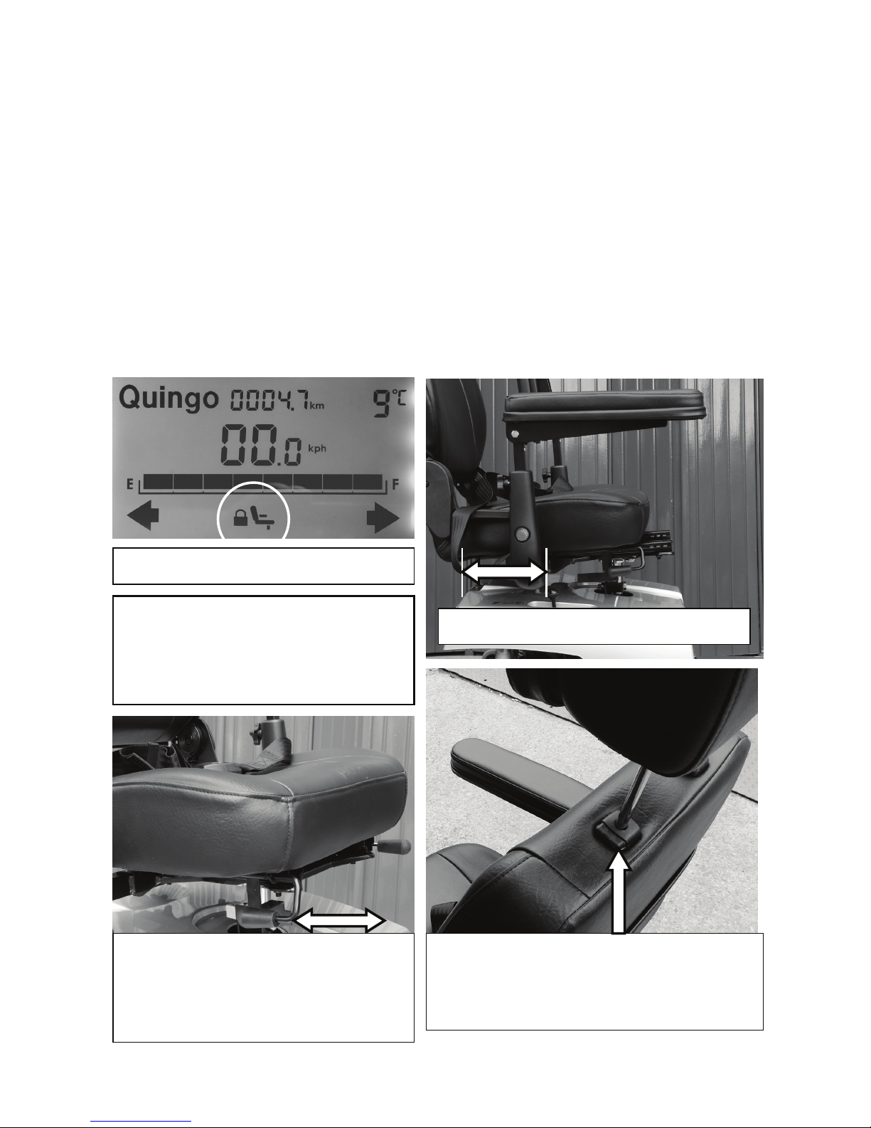
Seat Slider: Allows the seat to be adjusted forwards or backwards. Pull the lever upwards
and adjust to suit. Release the lever and move the seat slightly back and forth until you hear
the seat lock. Always keep the seat as far forward as possible as this aids stability of the
scooter. When locked, the seat will not be able to be moved.
If you require extra legroom for getting on or off the scooter there is a special feature to help.
Locate the lever on the right hand side of the seat. Pull it upwards. Holding the lever up push
the seat fully back as far as it will go. This will give you extra room to get on the vehicle. Pull
the seat forward and adjust to your riding position. If the seat is not in the correct position for
driving and you switch on the ignition a warning will come up on the display. It will show a
flashing seat & lock (ringed) plus the hazard lamps will flash with the warning horn.
Pull the seat forward until the warning stops.
Extra access adjustment
REMOVE THE IGNITION KEY
BEFORE ADJUSTING ANYTHING.
ALWAYS MAKE SURE THE SEAT
IS LOCKED BEFORE RIDING
THE SCOOTER
To adjust the headrest height, push the button
inward and lift or lower the headrest to the
required height. When a “click” is heard the
headrest is locked.
To adjust the legroom pull the lever
upward and push or pull the seat to the
correct position. Release the lever and
push or pull on the seat until you hear a
click. The seat is now locked.
Display warning

15
Backrest, Footplates & Seatbelt Adjustments
Backrest Adjustment
To adjust the backrest angle, locate the lever situated on the right hand side of the seat.
Pull it upwards and adjust as required. Release the lever and the backrest will lock.
Footplate Adjustment
The footplates can be adjusted for angle and reach. It is recommended that a service
engineer carry this out. If you want to adjust it back or forward loosen the lock as shown.
Move into position and lock. Some vehicles are fitted with a lock nut.
You will notice that the footplates are springy when pushed. This is designed to increase
blood flow to the legs. When you are on the scooter push occasionally up and down on
the plates. This is good exercise and will help you with your circulation.
Backrest adjustment
Footplate lock
Use the seat belt
whenever you drive
the vehicle. Pull the
belt across your lap
and connect the
buckle. This is
achieved by pushing
the 2 parts together.
When they lock you
will hear a “Click”.To
release push the red
button market “Push”
and the buckle will
release.
MAKE SURE THE
BELT IS ADJUSTED
CORRECTLY AT
ALL TIMES
Footrest Adjustment
Press button in
where it says “press”
Footrest removed for clarity
Clamping
knobs
Angle
adjustment
stop

16
Tiller Features
The tiller carries all the important connectors. When sitting on the scooter push the tiller fully
forward (See how to adjust the tiller on this page)
To adjust the tiller pull the lever down and
adjust the tiller by pulling backwards or forward.
Release the lever and the tiller will lock.
Ignition switch
Insert key and turn to the right.
IMPORTANT NOTE
If you leave the ignition on and do
not use the scooter for about 10
minutes it will switch itself off.
To reset the ignition turn the switch
off and back on again. Always
remove the key when not in use
Coat or
bag hook
Only use
when the
scooter is
stationary
The 12 volt outlet
Allows you to run a cigarette
lighter, mobile phone, GPS unit,
heated grips etc.
You will need a cigarette lighter plug,
which is standard on most products.
The socket is similar to a car power
point or cigarette lighter.
Always replace the waterproof
cover when not in use.
IMPORTANT NOTE USING
THE POWER OUTLET WILL
REDUCE THE VEHICLES RANGE.
Battery charger socket,
This is the point where the battery charger is
connected. Close the waterproof cover when
not in use.

17
Seat Height Adjustment & Front Basket Removal
Removing the Basket
To remove the basket pull the pin out and simply
pull the basket forward.
To refit the basket, line up the 2 tubes and push
the basket as far forward as possible.
Push the pin in fully.
Maximum Weight
The maximum
load weight of the
basket is 8kg
To adjust the seat
height, remove the seat
and rear cover. Release
the bolt with 2 x 17mm
spanners. Remove the
bolt and raise or lower
the seat to suit. Replace
the bolt in the desired
hole and tighten.
Important: It is
recommended that
adjustment be carried
out by a service
engineer.
Seat Height Adjustment

18
Transporting the Scooter
Transporting the Scooter
If you want to transport the scooter in a car, first remove the seat. Rotate the seat
and pull the seat upwards. You may need help with this, as the seat is heavy.
You will also require ramps to assist loading the scooter into the vehicle. Contact your
service provider for supply. The space you require is139cm long x 61cm high x 66cm
wide for the scooter.
1. Use the backrest adjustment lever
to fold seat as shown
2. To remove the seat pull the revolving
seat lever up, turn the seat & lift.
(Caution this is heavy- seek advise
and assistance) Remove the rear cover
by lifting upwards. This is attached with
Velcro.
3. Release the tiller and fold until handlebars touch rear body.
NB. Model shown here is Quingo Toura but the principle is identical.

19
Battery Charging
Connection Instructions
When you receive your scooter the
batteries are partially charged.
Fully charge for 12 hours before use.
Place your scooter in an area that is dry
and well ventilated. Make sure a power
point is nearby.
The scooter should be switched off and
the key removed.
Turn off the mains switch. Never connect
or disconnect the charger with the mains
turned on.
Connect the charger to the charging
socket on the tiller (see Fig 1.)
Once the charger is connected, switch
on the mains.
The power-on lamp illuminates red when
switched on. The charger lamp starts
yellow, changes to green when charged
(charge for the full duration 8-12 hours).
Switch off the mains and remove the
plug from the battery when fully charged.
Do not leave the charger plugged in with
the power off. This will discharge your
battery.
Correct charging prolongs battery life.
Fig 1. Insert charging plug here
Mains connector
Yellow=charging
Green=fully charged
Red = power on
On(I) off(O) switch

20
Battery Charging
GENERAL NOTES REGARDING THE BATTERY CHARGER
Battery chargers are subject to regular upgrades. For full instructions read the leaflet
supplied with the charger, which can be found in the Battery Charger box.
IMPORTANT
Batteries have a limited guarantee; if they have not been charged correctly and they fail,
they will not be replaced under the guarantee. An engineer will be able to detect “misuse
or neglect” immediately, so follow the correct charging procedures to prolong their life.
Charging your Batteries.
1. Always use Gel/AGM type batteries as replacements. NEVER use car lead acid
batteries. If in doubt ask your Quingo Service Advisor.
2. Always use the correct charger. Never use a lead acid (Car type) charger. If the
fully charged light does not come on (normally green, varies with charger type) you
may have a battery or charger problem.
3. When storing, fully charge the batteries every week - never let them run low.
4. Do not leave the ignition on during charging
5. Do not leave the charger switched off with the plug connected to the vehicle. This
will discharge the batteries to zero.
6. Charge the vehicle in a well ventilated area.
7. Do not charge the vehicle in the open air. The battery charger is not waterproof.
8. Always charge the batteries fully after use (Normally over night). Do not part
charge.
9. As the batteries age they will lose their electrical capacity so the range will
decrease.
10. Hilly areas have a great affect on the range. As the motors heat up, they lose their
efficiency, increasing demand on the batteries and decreasing the range.
11. If a faulty battery is found it is recommended to change both batteries.
12.
If the charger is left on for a long period it will not affect the batteries. The charger is
fully automatic and will switch off when the batteries are full. However, if the vehicle
is not being used for a long period it is recommended that the charger should be
used every week to top up and then disconnect.
13. If the batteries have been discharged for a long period, do not attempt to charge.
Contact your service provider for advice.
Caution: If one or both batteries are damaged they could heat
up when charging or in an extreme case explode. Ensure that all
damaged batteries are disposed of by the supplier.
Table of contents
Other AVC Scooter manuals


