Izip VIA MEZZA User manual

Please Refer to your Owner’s Manual for Detailed Setup Instructions
Technical & Customer Service: 1-800-377-4532

Helpful Tools:Included in your parts box:
Scissors•
Bicycle grease•
10mm wrench•
Pedals•
Toolkit (4+5mm combo wrench, 13+15mm•
combo open-end wrench)
Touch-up Paint•
Assembly will take about an hour
Note: When working on your bicycle as instructed by this guide, please refer to the torque values chart on the final pages for detailed torque requirements.
Under- or over-tightened components may loosen or break, causing a fall.
Steps in this guide that call for the use of bicycle grease do so in the interest of keeping your bicycle in working condition for as long as possible. Grease
is not absolutely vital to the assembly of this product, but failure to apply it as directed could cause parts to seize over time and irreparably damage the
frame or components.
Because bicycle parts tend to be greasy, it is recommended that you lay down a tarp or sheet to protect your oor if assembling the bike indoors.
It is best to remove the protective packaging during the assembly process only as needed, leaving some intact to protect the bike during assembly.
During assembly it may be helpful to reference the photos on the cover of this guide and on the bicycle box if you are unsure of any steps.
Please take the time to read the battery care and storage section of your manual for useful information on prolonging the life of your battery.
Assembly Tools
1. Carefully remove the bicycle from the box.
You should have a friend help you with this, as it is heavy. If you are
alone, you can lay the box on its side and gently slide the bike out. Stand
the bicycle upright on its fork and rear wheel, supported by the
kickstand.
2. Find the parts box and charger box. Inside the parts box you will nd
the tools and components you need to complete this assembly.
At this point you can begin charging your battery. The battery is
usually packaged in a brown cardboard box underneath the bike. The
charger is in a small white box, usually rubber-banded to the rack.
Recommend charge time is 6-8 hours. Plug the charger rst into the wall
outlet, then into the port on the side of the battery.
A solid red or blinking green light on the charger (depending on model)
indicates the battery is charging properly. A solid green light indicates that
the charger has entered trickle charge mode, and your battery is at least
80% full. For maximum range, please charge for the full recommended
time period (6-8 hours).
Please recycle
packaging materials!
Currie Technologies Technical and Customer Service 1-800-377-4532
A
C
Unpacking and Preparation
Front brake faces
forward, cables
properly routed to
right-side of frame
without twisting or
tangles
Pull back rubber boot. Squeeze brake arms
inward and pull “noodle” out of holder.
Boot
Noodle
Front Wheel
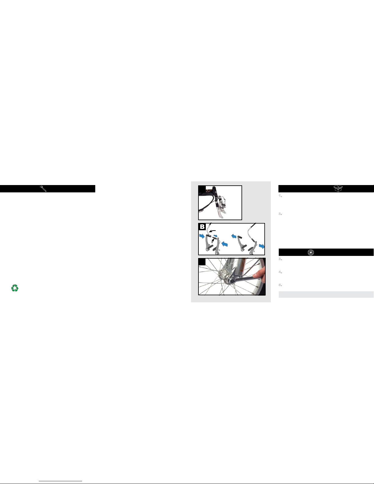
3. Cut the zip-ties holding the front wheel to the bike frame, then set
the wheel aside for now. Make sure the fork is properly aligned to
the bike; the brake should be facing away from the frame, and the cables
should not be twisted or tangled (Photo A).
4. Release the front brake by pulling back the rubber boot, squeezing
the brake arms together, then removing the “noodle” from its holder
(Photo B). This will allow you to install the front wheel. You will need to
reattach the brake by reversing this step once the front wheel is installed.
5. Remove the plastic dropout protector from the fork, then install the front
wheel. Tighten the axle nuts completely with the supplied 15mm
wrench (Photo C). Close the brake by reversing step 4.

Currie Technologies Technical and Customer Service 1-800-377-4532
6. Locate the bottom half of the steering column (usually zip-tied to the
handlebars, not attached to bike by any cables). Open the quick release
clamp and insert the top half of the steering column (attached to the bike) into
it (Photo D). Close the quick release securely, referring to the appendix to this
guide discussing quick release clamps for more information.
7. Unlock the handlebar post hinge, then fold the hinge open (Photos E&
F).
D
Handlebars
Currie Technologies Technical and Customer Service 1-800-377-4532
G
E1) Unlock quick
release F2) rotate lever away,
then open hinge
Steering column
bottom half
Stem
Steering column
top half
8. Remove black plastic the protective caps from the stem and
head tube.
9. Slide the end of the steering column (the stem) fully into the bicycles
head tube (Photo G), align the handlebars so they will be perpendicular
to the front wheel when they are raised, then tighten the wedge bolt
inside the hinge securely with the included 6mm Allen wrench (Photo
H). It is vital to your safety that this bolt is tightened securely!
Failure to fully tighten the bolt could cause the wheel to turn
away from the handlebars, causing a crash.
10. Raise the handlebars (Photo I), then lock the hinge quick release lever
(by reversing step 7). If the quick-release lever does not provide a fair
amount of resistance against being closed, or if the handlebars do not
feel securely clamped after closing the lever completely, you will need
to re-adjust the lever by tightening the 10mm preload-adjusting
nut (Photo J) until the lever closes tightly.
HIJ
Wedge bolt
Preload-
adjusting nut

Seatpost
Currie Technologies Technical and Customer Service 1-800-377-4532
Pedals
F
L
11. Unpack the saddle and seatpost. Open the quick-release lever on
the bicycle’s seat tube, then insert the seatpost into the seat tube.
Set the saddle to a comfortable height, then close the seat tube quick
release (photo K), referring to the appendix to this guide on quick release
clamps.
12. Find the pedals in your parts box. Grease the threads and thread
them securely into the crank arms using a 15mm open-end
wrench (Photo L). Note that the pedals have opposite thread directions
and must go on a specic side of the bicycle. The pedal meant for the
drive-side (the side of the bicycle with the chain and gears) has a standard
thread, which is tightened clockwise. The non-drive-side pedal has a
reverse, non-standard thread. It must be turned counter-clockwise to be
screwed in. The pedals are marked ‘R’ and ‘L’ for “Right” and “Left.”
Currie Technologies Technical and Customer Service 1-800-377-4532
M
10mm
nut
Thin
washer
Fender
bracket
Thick
washer Bicycle
fork bridge
Thin
washer
Bolt
Fender bolts
N
Fender
Front of bicycle
13. Install the front fender using the three bolts already attached to the fork; see diagram
M & photo N. Make sure the fender does not rub against the wheel or interfere with the
front brake.
14. Adjust your front and rear brakes. Your brakes may not be fully adjusted from
the factory; refer to your owner’s manual for detailed instructions on brake adjustment
or consult a professional bike mechanic if you are not comfortable making these
adjustments yourself. Do not attempt to ride your bicycle without properly adjusting
the brakes!
Fenders

Your Izip Via Mezza folds at two hinges; one on the frame and one on the
steering column.
1. Unplug the battery, pull the locking pin (left side) to release it, then pull the
battery pack out of the frame. (Photos Oand P)
2. Fold the pedals by pushing the black portion towards the frame, then
swinging it down (Photo Q). Repeat for the opposite side.
O
PQ
Currie Technologies Technical and Customer Service 1-800-377-4532
Folding 3. Open the seat post quick release, then lower the saddle completely. See
the appendix to this guide discussing quick release clamps for more
information.
4. Slide the top handlebar section down completely and lock in place
5. Open the quick release securing the handlebar hinge, then fold the
bars down. See the Handlebars section of this assembly guide for more
information.
Pull locking pin to
release battery pack
R
ST
Currie Technologies Technical and Customer Service 1-800-377-4532

Currie Technologies Technical and Customer Service 1-800-377-4532
U
V
6. Unlock the frame hinge by opening the quick release lever,
swinging it outward, then pulling the lever upward to disengage
the locking pin (Photos U and V). Fold the frame in half at this
hing. This procedure is similar to folding the handlebars.
The bike, completely folded
Installation:
Your bicycle comes with a 24 volt sealed lead acid battery. To install the battery, simply slide it into the empty
space behind the seat, as shown in photo W. You may need to release the locking pin on the left side of the
bicycle to do so, as shown in the photo.
This type of battery does not have a ‘memory’, and riding on a partial charge will not harm the battery in any way.
Recharge time for this battery is 6-8 hours to reach a full charge.
Currie Technologies Technical and Customer Service 1-800-377-4532
W
X
Operation
To turn your bicycle on, simply toggle the battery’s ON/OFF switch to the ON position. The lights on the
throttle (Photo X) will illuminate, indicating the charge level of the battery.
The Via Mezza uses the Currie “Twist and Go” (TAG) system. Simply twist the
handlebar-mounted throttle towards you to power up the motor.
Battery
ON/OFF switch

Currie Technologies Technical and Customer Service 1-800-377-4532
Before your rst ride...
• Remove all remaining packaging on the bike.
• Check the operation of your front and rear brakes by pushing the bike forward and operating the brake levers.
• Check the tightness of all nuts and bolts, especially the stem bolts and the bolts securing the brake levers and shifters to the handlebars.
• Make sure the stem’s wedge bolt is tight. Check that it is tightened properly by standing over the front wheel, holding it with your thighs, then
trying to turn the handlebars. If the handlebars can be turned independently of the wheel, the wedge bolt must be tightened further.
• Make sure all frame quick release levers are tightened securely. See the appendix to this guide discussing quick releases for more
information.
• Make sure your front wheel is secure in the frame.
• Make sure your tires are lled to the pressure recommended on the sidewall. Over- or under-inated tires can blow off the rim and cause
a fall. We recommend using a bicycle pump with pressure gauge.
• Test power: lean the bike on its kickstand, raising the rear wheel off the ground. When the bike is powered on (indicated by the throttle lights) you
can test system power by twisting the throttle and watching the rear wheel. Refer to the troubleshooting chart on this page for assistance if the bike
will not power on.
Bike won’t turn on (no lights on
throttle)
Battery not seated properly against rack terminals
Need to press handlebar ON/OFF switch
Battery not charged
Throttle lights work, but motor
will not run
Bike may be in Pedal Assist mode. Press the green button next to
the throttle to change to Twist-and-Go mode.
Brakes rub when riding Re-adjust brakes, referring to owner’s manual
Gears/chain make clicking or
grinding noises while riding
Re-adjust drivetrain, referring to owner’s manual
Can someone help me with...? Call the Currie Technologies technical and customer service
department at 1-800-377-4532
Refer to owner’s manual for detailed troubleshooting chart
Currie Technologies Technical and Customer Service 1-800-377-4532
This page intentionally left blank

Currie Technologies Technical and Customer Service 1-800-377-4532 Currie Technologies Technical and Customer Service 1-800-377-4532
Adjusting a quick release seatpost clamp
In a seatpost quick release system, the seatpost is clamped in place by the force of the quick
release cam pushing against one side of the clamp and pulling the tension adjusting nut,
by way of the skewer, against the other. The amount of clamping force is controlled by the
tension adjusting nut. Turning the tension adjusting nut clockwise while keeping the cam lever
from rotating increases clamping force; turning it counterclockwise while keeping the cam
lever from rotating reduces clamping force. Less than half a turn of the tension adjusting nut
can make the difference between safe clamping force and unsafe clamping force.
1. With the quick release clamp in the OPEN position, insert the seatpost, with saddle
attached, into the bicycle’s seat tube.
2. Swing the quick release lever into the CLOSED position.
3. Grab the saddle with both hands and attempt to rotate it (and thus rotate the seatpost in
the seat tube).
4. If you are able to force the seatpost out of alignment with the frame, the seatpost clamp
needs to be adjusted. Holding the quick release lever in the OPEN position with one
hand, tighten the tension adjusting nut with your other hand about 1/2 turn clockwise.
5. Attempt to swing the lever into the CLOSED position. If the lever cannot be pushed all
the way to the CLOSED position (gure b), return the lever to the OPEN position, then
turn the tension adjusting nut counterclockwise one-quarter turn and try tightening the
lever again. Repeat steps 3, 4 & 5 until proper quick release tension is achieved.
Tension adjusting
nut
open
Closed
Many Izip and Ezip bicycle models use quick release (QR) levers to facilitate common tasks such as front wheel removal and seat height adjustment.
When properly adjusted, quick release levers are both safe and convenient, but you must understand and apply the correct technique to adjust them
properly before riding your bicycle to prevent serious injury or death from a fall.
Quick release levers use a cam action to clamp the wheel or other components in place. Because of their adjustable nature, it is critical that you
understand how they work, how to use them properly, and how much force you need to apply to secure them.
Warning: The full force of the cam action is needed to clamp the wheel securely. Holding the nut with one hand and turning the lever like a wing nut is
NOT a safe or effective way to close a quick release and will not clamp the wheel or other components safely.
QUICK RELEASE USAGE
Riding with an improperly adjusted wheel quick release can allow the wheel to wobble or fall off the bicycle, which can cause serious injury or death.
Therefore, it is essential that you:
1. Ask your dealer or a local bike shop to help you make sure you know how to install and remove your wheels safely.
2. Understand and apply the correct technique for clamping your wheel in place with a quick release.
3. Each time, before you ride the bike, check that the wheel is securely clamped.
Appendix: Quick Release Levers

Component Recommended Torque Value (in-lb) Nm
Headset, Handlebar, Seat area
Seat xing bolt (seat rail binder) 174 - 347 19.7 - 39.2
Stem handlebar binder bolts (2) 174 - 260 19.7 - 29.4
Stem wedge (binder) bolt - quill type for
threaded headset 174 - 260 19.7 - 29.4
Threaded headset locknut 130 - 150 14.7 - 16.9
Threadless stem clamp bolts 120 - 144 13.6 - 16.3
Crankset, Bottom Bracket, Pedal area
Chainring bolt (aluminum) 44 - 88 5.0 - 9.9
Chainring bolt (steel) 70 - 95 7.9 - 10.7
Crank bolts 305 - 391 34.5 - 44.2
Pedal (into crank) 307 - 350 34.7 - 39.5
Derailleur, Shift lever area
Front derailleur cable pinch 44 - 60 5.0 - 6.8
Front derailleur clamp mount 44 - 60 5.0 - 6.8
Rear derailleur cable pinch bolt 35 - 45 4.0 - 5.1
Rear derailleur mounting bolt 70 - 86 7.9 - 9.7
Shift lever (MTB thumb-type) 22 - 26 2.5 - 2.9
Shift lever (SRAM “grip-shift” type) 17 1.9
BICYCLE TORQUE VALUES
Component Recommended Torque Value (in-lb) Nm
Wheel area
Wheel axle nuts to frame/fork 260 - 390 29.4 - 44.1
Brakes
Brake cable pinch bolt (linear pull) 53 - 69 6.0 - 7.8
Brake caliper (linear pull) to frame/fork 45 - 60 5.1 - 6.8
Brake lever (MTB type) 53 - 69 6.0 - 7.8
Brake pad to caliper 50 - 70 5.6 - 7.9
Disc brake caliper mount 60 - 90 6.8 - 10.2
Disc rotor to hub 35 - 55 4.0 - 6.2
BICYCLE TORQUE VALUES, CTD.

Notes: Notes:

9453 Owensmouth Ave, Chatsworth, CA 91311
Phone: +1 800.377.4532
Fax: +1 818.734.8199
www.currietech.com
Table of contents
Other Izip Scooter manuals
Popular Scooter manuals by other brands

wayscral
wayscral TAKEAWAY E100 Translation of the original instructions

SoFlow
SoFlow SO4 PRO Genuine operating instruction

Pride Mobility
Pride Mobility Colt Series owner's manual

Chillafish
Chillafish SKATIESKOOTIE CPSS01 user manual

Pride Mobility
Pride Mobility Maxima Scooter SC940 owner's manual

Master
Master 12 user manual