Beale Street Audio BA251 User manual
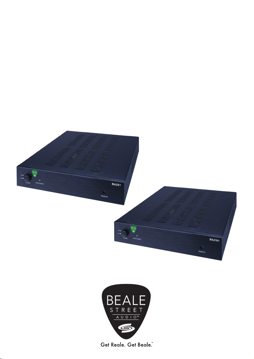
Beale Street Audio
BA251, BA2101 Digital 2.1 Channel Amplifiers
Installation Guide

2
Introduction
Congratulations and thank you for purchasing the Beale Street Audio BA251 &
BA2101 Digital 2.1 Channel Audio Amplifier!
The half rack size and advanced design deliver a whole lot more than just great,
powerful, clear audio in a small package. The BA251 delivers a true 50 watts per
channel at 8 ohms, making it the perfect companion for all Beale Street Audio
in ceiling and in wall speakers while the BA2101 delivers a true 100 watts per
channel at 8 ohms! Though we’d rather you use our speakers, they will also play
nicely with other branded speakers... when those situations are just unavoidable.
Are you a bass freak? If so, these amps have a line level subwoofer output that
can be used to drive a Beale Street Audio subwoofer amplifier and subwoofer for
additional bass extension and presence. (Of course, if you have to, you can use
other branded amps and subs, but c’mon...Get Beale!)
Beyond all of the great audio amplification and subwoofer flexibility, are the other
great features that make the BA251 and BA2101 so powerful. Let’s start with
three audio inputs, including stereo line level, Digital Optical (Toslink) and digital
coax. These inputs are auto-sensing so they can automatically turn ON based
upon setup options, making system control as easy as pressing a play button or
turning on a TV.
The BA251 and BA2101 also features IR control from the IR remote for source
select, volume, and mute control. The built-in IR eye on the front and IR input jack
on the back of the unit increases installation location options and can be hidden
away in a cabinet or closet and still be controlled via remote control using the
provided IR extension cable.
Want to control the amp using a different remote? No problem! The BA251 and
BA2101 both offer easy push button IR learning so any remote will be able to
control volume, source selection, and muting functions.
So let’s see...compact size, big power, sub out, three audio inputs, auto-sensing, IR
control of the amp, wow, that’s a whole lot of stuff right?
So yes, the best things do come in small packages.
Please read and follow the instructions in this User Guide to assure you are getting
the most from your new Beale Street Audio 2.1 Channel Amplifier.

3
Features
50W, 2 Channel Amplifier
BA251
• Compact size...fits almost anywhere
• 50W per Channel at 8 Ohm, 160W bridged
• Anti-clipping Output Limiter
• Stereo, Mono/Bridge Modes
• Cool, efficient digital design
• Stereo Audio Line Level Input (RCA)
• Digital Optical Audio Input (Toslink and Coax)
• Line Level Subwoofer Output (RCA)
• Push-button IR Learning
100W, 2 Channel Amplifier
BA2101
• Compact size...fits almost anywhere
• 100W per Channel at 8 Ohm, 300W bridged
• Anti-clipping Output Limiter
• Stereo, Mono/Bridge Modes
• Cool, efficient digital design
• Stereo Audio Line Level Input (RCA)
• Digital Optical Audio Input (Toslink and Coax)
• Line Level Subwoofer Output (RCA)
• Push-button IR Learning
What’s Inside?
• BA251 50W Amplifier
• IR Extension Cable
• Remote
• Mounting Accessories
• AC Power Cord
• Product Manual
• BA2101 100W Amplifier
• IR Extension Cable
• Remote
• Mounting Accessories
• AC Power Cord
• Product Manual
BA251 BA2101
4
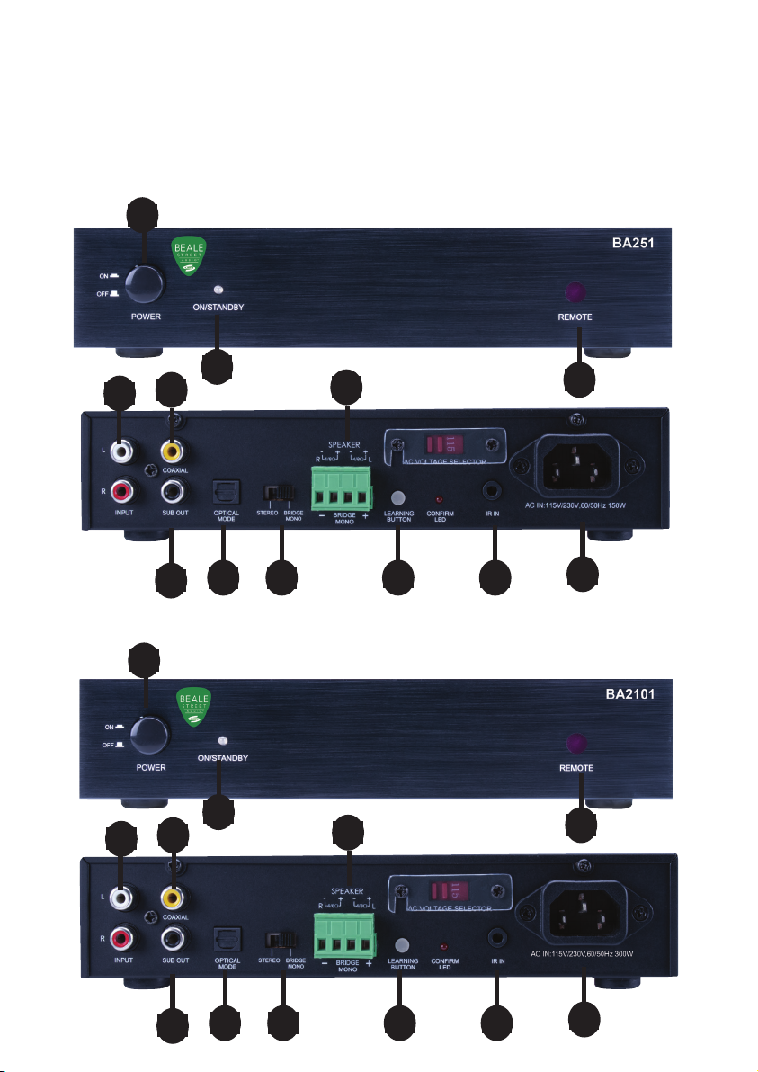
Inputs & Outputs
These connectors connect things to the BA251 and BA2101...some actually
do some other stuff too...
23
45
BA251
BA2101
67 8
9
10
1
11 12
23
45
67 8
9
10
1
11 12

5
1. Power On/Off button - Press in to power unit ON
2. On/Standby - LED flashes or illuminates solid to indicate various setup modes. (Solid
Green - Power ON; Solid RED - Power OFF or Standby depending upon setup)
3. IR Sensor - IR sensor ‘sees’ the IR commands from the IR Remote, or other properly
configured programmable remote to control volume, source selection, mute, and
power
4. Line In (L&R) - Two RCA jacks; Analog audio sensing input. Using a stereo RCA cable,
connect to the L&R line level audio output on a source to be played though the amp.
If the source has variable output, be sure to lower the volume on the source prior to
turning the source and amp on the avoid unintentional damage to the amp and/or
speakers. Set source to an appropriate output level during audio level setup.
5. Digital Coax In- Coax (RCA) digital audio sensing input. Using a mono RCA cable,
connect to the digital coaxial audio output on a source to be played though the amp.
If the source has variable output, be sure to lower the volume on the source prior to
turning the source and amp on the avoid unintentional damage to the amp and/or
speakers. Set source to an appropriate output level during audio level setup.
6. SUB OUT - One RCA jack. Outputs line level low frequency content to a powered
subwoofer. Using a mono RCA cable, connect to the Sub IN or LFE jack on a powered
subwoofer or subwoofer amp.
7. OPTICAL IN - S/PDIF Optical Terminal (Toslink). Digital audio sensing input. Using
a optical audio cable, connect to the optical/Toslink audio output on a source to be
played though the amp. If the source has variable output be sure to lower the volume
on the source prior to turning the source and amp on the avoid unintentional damage
to the amp and/or speakers. Set source to an appropriate output level during audio
level setup.
8. Stereo/Bridge/MONO- Switch to have the amp put into Stereo or Bridged/Mono mode
9. SPEAKER TERMINALS - Four-position plug-in screw terminal. Outputs speaker
level audio to left and right channel speakers or a sound bar. Using 16AWG (min)
speaker wire, connect to the appropriate speaker terminals on a sound bar or left
and right speakers. Before connecting the speaker wire to the amp, twist the ends of
the speaker wire so there are no loose ends that can cause shorts. Observe proper
polarity. Confirm connections.
10. IR Learning Button- Press to enable IR learning. This allows ANY IR remote to be able
to control the volume, power, mute, and source selection functions of the BA251 and
BA2101.
11. IR RECEIVER IN – Connect using the provided IR Receiver/Extension cable to be able
to control and learn IR commands to control the BA251 and BA2101 amps. The amp
will turn OFF when no audio input has been sensed for fifteen minutes.
12. AC POWER TERMINAL (100-240V-50/60Hz 2.5A) - Universal power connector.
Automatically selects AC power mode (110VAC/230VAC) when connected to AC
power. After all connections have been made, connect the supplied AC Power Cord to
an unswitched AC power outlet.
6
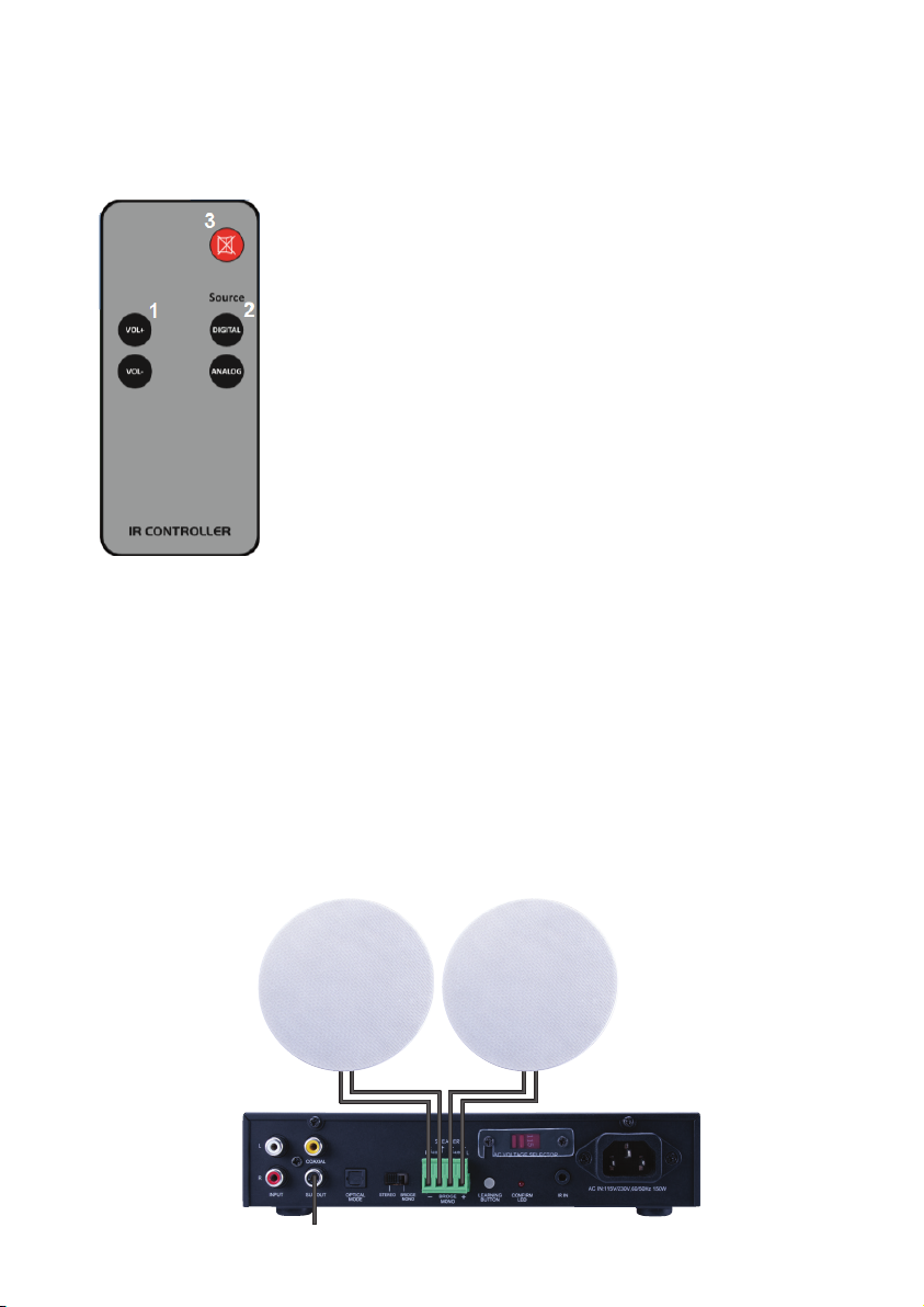
IR Remote
Push the buttons...stuff happens...
1. VOLUME UP/DOWN- Press ‘VOL+’ to increase volume.
Press ‘VOL-’ to decrease volume
2. INPUT SELECT –
• Digital - Press to select the source connected to the
Optical/Toslink or Digital Coax input
• Analog - Press to select the source connected to stereo
analog RCA input
3. MUTE - Press to mute/unmute
Installation and Connections
All connections are conveniently placed for easy wire management, convenient
connections and simple service. The illustration shows a typical home entertainment
system for TV audio with stereo in ceiling speakers with an optional subwoofer amp and
subwoofer.
BA251
Stereo Setup
Audio Speaker
Sub OUT to
Sub Amp Line IN

7
BA2101
Mono/Bridge Setup
Audio Speaker
Sub OUT to
Sub Amp Line IN
Sub OUT to
Sub Amp Line IN
Mono/Bridge Setup
Audio Speaker
Stereo Setup
Audio Speaker
Sub OUT to
Sub Amp Line IN

8
Connections
NOTE: Do not connect the AC power cord or turn the amp on until all connections have
been made and confirmed. Making connections with the power on can result in...well...
undesirable circumstances that may not be covered under the factory warranty.
Optical In (TV Audio Connection)
1. Using a Digital Optical Audio cable, (Toslink) connect the Digital Optical Audio OUT
on the TV (or other source) to the Optical IN on the amp. To select this input, press
DIGITAL on the IR Remote.
Sub Out (Beale Street Audio Subwoofer Amp Connection)
1. Using a mono RCA-RCA cable with gold ends, connect the Sub OUT on the BA251/
BA2101 to the Sub IN on the Beale subwoofer amp , a powered sub or other
subwoofer amplifier.
L-L+R-R+ (Speaker Connections)
1. Use 16AWG (min) 2-conductor stranded speaker wire for speaker connection
2. Strip approximately 1/2 to 3/4 of an inch off the ends and twist the strands together
so there are no loose ends that can cause shorts.
3. While observing proper wire polarity, insert the stripped and twisted ends of the
speaker wire into the appropriate + and - terminals for the left and right speakers.
4. Tighten the terminal screws
5. Confirm connection and polarity
6. Connect the speaker wires to the appropriate + and - terminals on the left and right
speakers
7. Confirm connection and polarity
Line In (Auxiliary Audio Source)
1. Using a stereo RCA-RCA patch cable connect the L&R line level audio OUTs on a
Bluetooth audio receiver or other source to the L&R Line IN on the BA251/BA2101. To
select this input, press ANALOG on the IR Remote.
AC Power Supply
1. After all connections have been made connect the supplied AC Power Cord to an
unswitched AC power outlet. Automatically selects AC power mode (110VAC/230VAC)
when connected to AC power.

9
Operation
ON/OFF (Audio Signal)
1. The BA251 and BA2101 is auto-sensing, and can automatically turn ON with the
presence of an audio signal on the Digital Optical inputs, Line IN, or IR Receiver IN. By
default, the amps will turn OFF when there has been no audio signal on any input for
three minutes.
Audio Signal ON Setup via IR Remote
1. The BA251 and BA2101 will default to Line IN out of the box. In default, it is not
necessary to do the following setup if using Line IN. Turn amp and source ON.
ON/OFF (IR)
1. If you are a major control freak and just have to have the ability to turn the amp ON/
OFF, press the Power button once to turn the amp ON, and press it again to turn the
amp OFF.
Volume
• VOLUME UP (VOL+) - Press to increase volume. Turn it up! YAY!!!
• VOLUME DOWN (VOL-) - Press to decrease volume. Turn it down! BOO!!!
IR Learning
What...you don’t want to have to use more than one remote to control your system???
WOW...some people!!! Well...if you insist...here’s what you can do to use a TV or other
preprogrammed remote to control the BA251/BA2101. (You can also teach the IR
commands from the BA251 and BA2101 IR Remote to a programmable IR system remote
if you prefer.)
1. Turn on the units, after 10 second press the IR Learning Button for 2 seconds until
the IR Confirm LED blinks slowly. If entry the learning mode and don’t do anything, 60
seconds after will exit
2. Place your remote control about 3-4 inches (7-10cm) away from the IR Learning
window , aiming the remote directly at the IR Learning window
3. The Vol +, Vol -, Analog, Digital and Mute commands must be learned in sequence (1st
Vol+, then Vol -, then Analog, then Digital, then Mute.)
a. Press the remote’s Vol + key until the IR Confirm LED blinks for 5 times
b. Press the remote’s Vol – key until the IR Confirm LED blinks for 5 times
c. Press the remote’s Analog key until the IR Confirm LED blinks for 5 times
d. Press the remote’s Digital key until the IR Confirm LED blinks for 5 times
e. Press the remote’s Mute– key until the IR Confirm LED blinks for 5 times
Note: The units exits the IR Learning Mode automatically after learning the Mute command

10
Description BA251 BA2101
Power Output
2x50W RMS @ 8Ω 2x100W RMS @ 8Ω
2x80W RMS @ 4Ω 2x150W RMS @ 4Ω
Bridge Output 160W RMS @ 8Ω 300W RMS @ 8Ω
Total Harmonic Distortion (THD) <1% at rated power
Signal to Noise Ratio >90 dB
Frequency Response 20Hz~20KHz +0/-2dB@ 8Ω
Line Level Input Sensitivity 670mV
Thermal Protection Yes
Short Protection Yes
Control IR and IR Learning
Dimensions (W x D x H) 8.4” x 9.8” x 1.7” (214mm x 250mm x 44mm)
Weight 2.95 lbs (1.39Kgs) 3.65 lbs (1.66Kgs)
AC Power 110V/230V, 60Hz/50Hz
Specifications

11
Limited Warranty
With the exceptions noted in the next paragraph, Vanco warrants to the original purchaser
that the equipment it manufactures or sells will be free from defects in materials and
workmanship for a period of two years from the date of purchase. Should this product, in
Vanco’s opinion, prove defective within this warranty period, Vanco, at its option, will repair
or replace this product without charge. Any defective parts replaced become the property
of Vanco. This warranty does not apply to those products which have been damaged due to
accident, unauthorized alterations, improper repair, modifications, inadequate maintenance
and care, or use in any manner for which the product was not originally intended.
Items integrated into Vanco products that are made by other manufacturers, notably
computer hard drives and liquid crystal display panels, are limited to the term of the warranty
offered by the respective manufacturers. Such specific warranties are available upon request
to Vanco. A surge protector, power conditioner unit, or an uninterruptible power supply must
be installed in the electrical circuit to protect against power surges.
If repairs are needed during the warranty period, the purchaser will be required to provide
a sales receipt/sales invoice or other acceptable proof of purchase to the seller of this
equipment. The seller will then contact Vanco regarding warranty repair or replacement.
TECHNICAL SUPPORT
In case of problems, please contact Vanco Technical Support by dialing 1-800-626-6445.
please have the Model Number, Serial Number (affixed to the bottom of the unit) and Invoice
available for reference during the call. Please read this Instruction Manual prior to calling
or installing this unit, since it will familiarize you with the capabilities of this product and its
proper installation. All active electronic products are 100% inspected and tested to insure
highest product quality and trouble-free installation and operation. The testing process
utilizes the types of high-definition sources and displays typically installed for entertainment
and home theatre applications. For additional information please visit www.vanco1.com.
LIABILITY STATEMENT
Every effort has been made to ensure that this product is free of defects. The manufacturer
of this product cannot be held liable for the use of this hardware or any direct or indirect
consequential damages arising from its use. It is the responsibility of the user and installer of
the hardware to check that it is suitable for their requirements and that it is installed correctly.
All rights are reserved. No parts of this manual may be reproduced or transmitted by any form
or means electronic or mechanical, including photocopying, recording or by any information
storage or retrieval system without the written consent of the publisher. Manufacturer
reserves the right to revise any of its hardware and software following its policy to modify
and/or improve its products where necessary or desirable. This statement does not affect the
legal rights of the user in any way.

A BRAND FROM
Vanco International, LLC
506 Kingsland Drive
Batavia, IL 60510
Phone: 800.626.6445 Fax: 630.879.9189
www.getbeale.com
www.vanco1.com
©2019
The Vanco logo, Sonic Vortex logo, and Beale Street Audio Inc. logo are registered trademarks of
Vanco International, LLC.
Vanco, Sonic Vortex, Beale Street Audio, Get Reale. Get Beale., the Vortex logo, and the Beale Street
Audio logo are trademarks of Vanco International, LLC.
This manual suits for next models
1
Table of contents
Other Beale Street Audio Amplifier manuals


