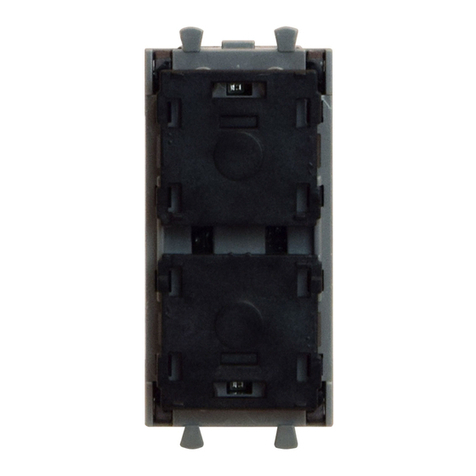
AVE 442TC01 User manual

INTRODUZIONE
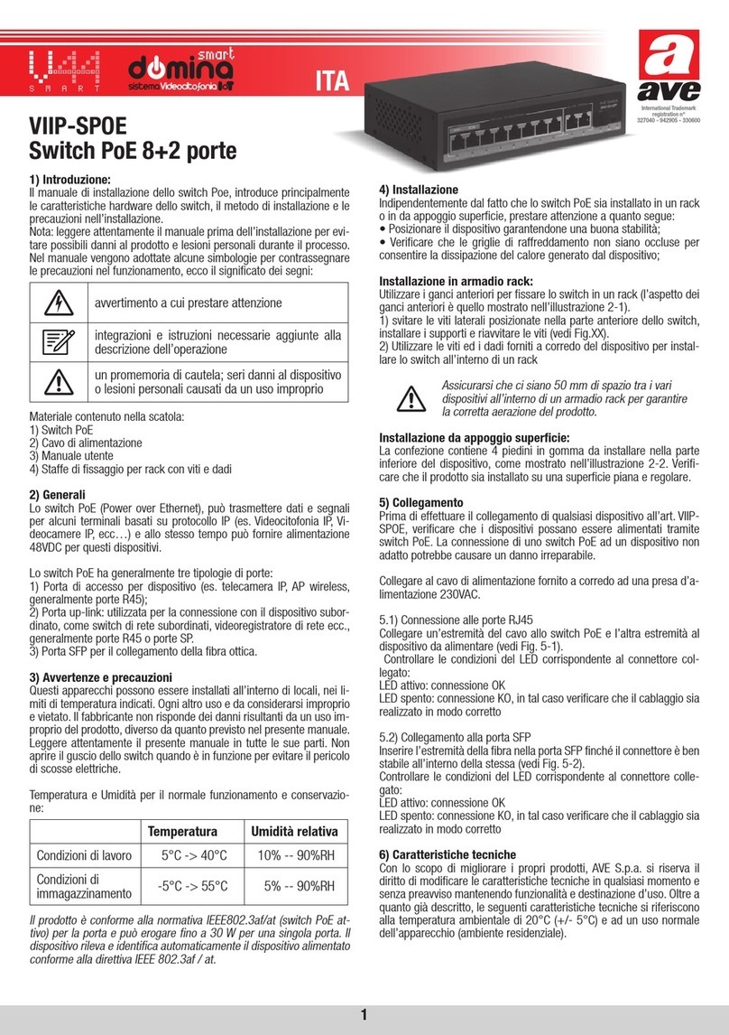
L’interruttore elettronico con uscita a relè 442TC01 è un comando con sensore a
sfioramento incorporato. Può essere comandato oltre che localmente anche da più
punti con pulsanti NA. Permette la selezione del modo di funzionamento monostabile
o bistabile. E’ munito di led per l’individuazione del comando al buio e va installato “a
scomparsa” sul retro di placche di finitura
CARATTERISTICHE TECNICHE
• Ingombro: 1 modulo “a scomparsa” S44
• Grado di protezione: IP40
• Morsettiera a 4 morsetti accessibili sul lato posteriore
• Tensione alimentazione: 230 Vca 50/60 Hz
• Variazione ammessa: - 15% + 10%
• Assorbimento: 24 mA a 230 Vca (0,6 W)
• Area frontale sensibile: tutto il fronte dell’apparecchio (vedi fig.1 area A1)
• Uscita a relè ad 1 contatto in chiusura (fase interrotta)
• Tipo di carico comandabile in corrente alternata:
- resistivo: 6A
- lampada incandescente: 6A
- lampada fluorescente: 6A
- trasformatore ferromagnetico per lampade ELV: 6A
- trasformatore elettronico per lampade ELV: 6A
• Comandi:
-appoggiando lievemente il dito sulla placca in corrispondenza di tutto il fronte
del dispositivo (vedi fig. 1);
-da più punti mediante pulsanti a sfioramento per comando remoto (cod.
442TC05) oppure pulsanti NA collegati alla fase
• Memoria di stato: garantisce la memorizzazione dello stato del relè
d’uscita in caso di interruzione di rete
• Led frontale (L1) per individuazione al buio (vedi fig. 1): all’avvicinamento della
mano il led emette una luce più intensa. Nota: nel caso in cui la luce emessa dal
led risulti essere fastidiosa, si consiglia di applicare sul fronte del dispositivo (retro
placca) l’etichetta di colore blu ricavabile dal set cod. ETI16
• Segnalazione acustica di ingresso/uscita dallo stato di inibizione temporanea
• Possibilità impostazione funzionamento uscita: monostabile o bistabile (vedi
paragrafo PROGRAMMAZIONE)
• Possibilità impostazione sensibilità funzionamento del dispositivo: al tocco della
placca o a 4mm di distanza dalla placca stessa (vedi paragrafo
PROGRAMMAZIONE)
• Funzione di inibizione temporanea per consentire la pulizia della placca (vedi
paragrafo PULIZIA PLACCA)
PROGRAMMAZIONE
Lateralmente è previsto un selettore Sw (vedi fig. 1) a due posizioni per la
programmazione del dispositivo. La lettura della posizione degli switch avviene
INTRODUCTION
The electronic switch with output relay 442TC01 is a control with incorporated touch
sensor. It can be controlled locally and from various points with NO buttons. It allows
to select a monostable or bistable operating mode. Leds allow the control to be seen
in the dark and must be installed "hidden" on the back of the front plates.
TECHNICAL SPECIFICATIONS
• Overall dimensions: 1x S44 "hidden" module
• Protection Degree: IP40
• Terminal board with 4 terminals accessible on the back
• Voltage input: 230 Vac 50/60 Hz
• Variation allowed: -15% +10%
• Input: 24 mA to 230 Vac (0,6 W)
• Sensitive front area: the entire front of the device (see fig. 1 area A1)
• Output relay with 1 contact on closing (cut off phase)
• Type of switchable loads in alternate current:
- resistive: 6A
- incandescent lamps: 6A
- fluorescent lamps: 6A
- iron core transformer for ELV lamps: 6A
- electronic step-down converter for ELV lamps: 6A
• Controls:
- rest the finger gently on the plate near the entire front of the device (see fig. 1)
- from various points with touch buttons for remote control (cod. 442TC05)
or NO buttons connected to the phase.
• Status memory: guarantees the memory of the state of the output relay
in case of black-out
• Front Led (L1) for locating in the dark (see fig. 1): when the hand approaches, the
all’atto dell’alimentazione del dispositivo. Pertanto per rendere attiva la
programmazione è necessario disalimentare il dispositivo stesso
Sensibilità
E’ possibile impostare la sensibilità dell’apparecchio, ovvero la distanza dal fronte
della placca per la quale si ha il riconoscimento del comando, agendo sul primo
switch:
- posizione ON: riconoscimento a 4mm dalla placca (sensibilità massima)
- posizione OFF: riconoscimento al tocco della placca (sensibilità minima)
IMPORTANTE!
Per l’utilizzo con placche "Allumia Touch" (placche in alluminio) è
necessario impostare il dispositivo alla massima sensibilità
Modo di funzionamento
Il modo di funzionamento dell’apparecchio, monostabile o bistabile, è impostabile
agendo sul secondo switch:
- posizione ON: funzionamento monostabile
- posizione OFF: funzionamento bistabile
PULIZIA PLACCA
Per consentire la pulizia della placca frontale senza continue attivazioni dell’uscita, è
possibile inibire temporaneamente il funzionamento del dispositivo mantenendo il
dito in corrispondenza dell’area A1 (vedi fig. 1) per un tempo di 10 secondi.
L’ingresso nello stato di inibizione viene evidenziato da una segnalazione acustica (4
beep). Lo stato di inibizione viene segnalato da un lampeggio lento di L1 (vedi fig. 1)
e permane per un tempo di 15 secondi, prima di ritornare automaticamente al
funzionamento ordinario. L’uscita dallo stato di inibizione viene evidenziato da una
segnalazione acustica (4 beep).
Allo stato di inibizione temporanea si può accedere anche rimuovendo e riapplicando
la placca con dispositivo alimentato
INSTALLAZIONE
L’interruttore deve essere installato ad incasso sul retro di placche di finitura, in
scatole rettangolari, scatole tonde Ø 60mm o quadrate
CONDIZIONI CLIMATICHE
Temperatura e umidità relativa di riferimento: 25 °C; UR 65%
Campo temperatura ambiente di funzionamento: da - 5 °C a + 35 °C
Umidità relativa massima: 90% a 35 °C
Altitudine max: 2000 m s.l.m.
CONFORMITÀ NORMATIVA
CEI EN 60669-2-1
SCHEMA DI COLLEGAMENTO (fig. 2)
I
l circuito di alimentazione (L-N) deve essere protetto contro i sovraccarichi
o
corto-cicuito
da un fusibile ad alto potere di interruzione o interruttore
automatico con corrente nominale non superiore a 10 A
led emits a brighter light. Note: should the led light be bothersome, we suggest
applying the blue sticker located in the set inside the device (back of the plate),
code ETI16.
• Possibility of excluding acoustic input/output signal from the state of temporary
inhibition.
• Allowed output function setting: monostable or bistable (see paragraph on
PROGRAMMING)
• It is possible to set the sensitivity function of the device: at the touch of the plate
or at a distance of 4mm from the plate itself (see PROGRAMMING paragraph)
• Temporary inhibition function to allow cleaning of the plate (see PLATE CLEANING
paragraph)
PROGRAMMING
There is a two-position Sw switch on the side (see fig. 1), to program the device. The
position of the switches is read when the device is connected. Therefore it is
necessary to disconnect the device in order to activate programming.
Sensitivity
It is possible to set the sensitivity of the device, in other words the distance from the
front of the plate where there is the identification of the control, acting on the first
switch:
- position ON: identification at 4mm from the plate (maximum sensitivity)
- position OFF: identification at the touch of the plate (minimum sensitivity)
IMPORTANT!
For use with "Allumia Touch" front plates (aluminium front plates) you
must set the device to the maximum sensitivity
Operating methods
The operating method of the device, monostable or bistable, can be set by acting on
ENG
ITA
Electronic touch switch with output relay “hidden” installation
Interruttore elettronico a sfioramento con uscita a rele’ Installazione “a scomparsa”

INTRODUCTION
L’interrupteur électronique avec sortie à relais 442TC01 est une commande avec un
capteur à effleurement incorporé. Il peut être commandé localement mais aussi à
partir de plusieurs points avec des boutons NO. Il permet la sélection du mode de
fonctionnement monostable ou bistable. Il est muni d’un led pour repérer la
commande dans l’obscurité et doit être installé de façon “cachée” sur l’arrière des
plaques de finition.
CARACTERISTIQUES TECHNIQUES
• Encombrement : 1 module “caché” S44
• Degré de protection: IP40
• Plaque à bornes à 4 bornes accessibles sur le côté postérieur
• Tension d’alimentation: 230 Vca 50/60 Hz
• Variation admise: -15% +10%
• Absorption: 24 mA à 230 Vca (0,6 W)
• Zone frontale sensible: toute la face avant de l’appareil (voir fig. 1 zone A1)
• Sortie à relais à 1 contact en fermeture (phase coupée)
• Type de charge qui peut être commandé en courant alterné:
-résistive: 6A
-lampe à incandescence: 6A
-lampe à fluorescence: 6A
-transformateur ferromagnétique pour lampes ELV: 6A
- transformateur électronique pour lampes ELV: 6A
• Commandes:
-en appuyant légèrement le doigt sur la plaque en correspondance avec toute la
face avant du dispositif (voir fig. 1)
-à partir de plusieurs points par l’intermédiaire de boutons à effleurement pour la
commande à distance (cod. 442TC05) ou bien par l’intermédiaire de boutons
NO reliés à la phase
• Mémoire d’état : elle garantit la mémorisation de l’état du relais de sortie en
cas d’interruption du réseau.
• Led frontal (L1) pour repérage dans l’obscurité (voir fig. 1): lorsque l’on approche
la main, le led émet une lumière plus intense. Note: si la lumière émise par le led
es gênante, nous conseillons d’appliquer l’étiquette bleue du set code ETI16 sur
la face avant du dispositif (arrière plaque).
• Signal sonore d’entrée/sortie de l’état d’inhibition temporaire.
• Possibilité d’insérer le fonctionnement de sortie: monostable ou bistable (voir
paragraphe PROGRAMMATION)
• Possibilité d’insérer la sensibilité de fonctionnement du dispositif: au touche de la
plaque ou à 4 mm de distance de la plaque (voir paragraphe PROGRAMMATION)
• Fonction d’inhibition temporaire pour permettre le nettoyage de la plaque
(voir
paragraphe NETTOYAGE PLAQUE)
PROGRAMMATION
Sur la partie latérale se trouve un sélecteur Sw (voir fig. 1) à deux positions pour la
programmation du dispositif. La lecture de la position des interrupteurs se fait lors
INTRODUCCIÓN
El interruptor electrónico con salida de relé 442TC01 es un mando con sensor por
contacto incorporado. Puede ser accionado además de localmente, también desde
más puntos con pulsadores NA. Permite la selección del modo de funcionamiento
monoestable o biestable. Está dotado de led para la localización del mando en la
oscuridad y se encuentra instalado de forma “a escondidas” en la parte posterior de
las placas de revestimiento.
CARACTERÍSTICAS TÉCNICAS
• Dimensión máx. ocupada: 1 módulo “a escondidas” S44
• Grado de protección: IP40
• Tablero de bornes con 4 bornes accesibles en el lado posterior
• Tensión alimentación: 230 Vca 50/60 Hz
• Variación admitida: -15% +10%
• Absorción: 24 mA a 230 Vca (0,6 W)
de l’alimentation du dispositif. Donc, pour rendre la programmation active, il est
nécessaire de couper l’alimentation au dispositif.
Sensibilité
Il est possible d’insérer la sensibilité de l’appareil, c’est-à-dire la distance de la face
avant de la plaque pour laquelle il y a reconnaissance de la commande en agissant
sur le premier interrupteur:
- position ON: reconnaissance à 4 mm de la plaque (sensibilité maximum)
- position OFF: reconnaissance au touche de la plaque (sensibilité minimum)
IMPORTANT!
Pour une utilisation avec les plaques "Allumia Touch" (plaques
d'aluminium) vous devez configurer l'appareil à la sensibilité maximale
Mode de fonctionnement
Le mode de fonctionnement de l’appareil, monostable ou bistable, peut être inséré
en agissant sur le deuxième interrupteur:
- position ON: fonctionnement monostable
- position OFF: fonctionnement bistable
NETTOYAGE DE LA PLAQUE
Pour permettre le nettoyage de la plaque frontale sans mettre la sortie
continuellement en marche, il est possible d’inhiber temporairement le
fonctionnement du dispositif en maintenant le doigt sur la zone A1 (voir fig. 1)
pendant un temps de 10 secondes. L’entrée dans l’état d’inhibition est mise en
évidence par un signal sonore (4 bips). L’état d’inhibition est signalé par le
clignotement lent de L1 (voir fig. 1) et dure pendant 15 secondes, avant de retourner
automatiquement au fonctionnement ordinaire. La sortie de l’état d’inhibition est
mise en évidence par un signal sonore (4 bips). Il est aussi possible d’accéder à
l’état d’inhibition temporaire en retirant et en remettant la plaque quand le dispositif
est alimenté.
INSTALLATION
L’interrupteur doit être encastré sur l’arrière des plaques de finition, dans des boites
rectangulaires, des boites rondes Ø 60mm ou des boites carrées.
CONDITIONS CLIMATIQUES
• Température et humidité relative de référence: 25 °C HR 65 %
• Champ de température ambiante de fonctionnement: de -5 °C à + 35 °C
• Humidité relative maximum: 90% à 35 °C
• Altitude maxi.: 2000 m au-dessus du niveau de la mer.
CONFORMITE NORMATIVE
• CEI EN 60669-2-1
SCHEMA DE RACCORDEMENT (fig. 2)
Le circuit d’alimentation (L-N) doit être protégé contre les surcharges
ou court-
circuit
par un fusible à haut pouvoir de coupure ou par un interrupteur automatique
avec courant nominal non supérieur à 10 A.
• Área frontal sensible: todo el lado frontal del aparato (véase fig. 1 área A1)
• Salida de relé con 1 contacto al cierre (fase interrumpida)
• Tipo de carga accionable con corriente alterna:
- resistiva 6A
- lámpara incadescente 6A
- lámpara fluorescente : 6A
- transformador ferromagnético para lámparas ELV 6A
- transformador electrónico para lámparas ELV: 6A
• Mandos:
-apoyando levemente el dedo sobre la placa en correspondencia con toda la
parte frontal del dispositivo (véase fig. 1)
- desde más puntos mediante pulsadores a roce para mando remoto
(cod. 442TC05) o bien pulsadores NA conectados a la fase
• Memoria de estado: garantiza la memorización del estado del relè de
salida en caso de interrupción de red
SPA
FRA
Interruptor eletrónico por contacto a roce con salida de relé instalación “a escondidas”
Interrupteur electronique a effleurement avec sortie a relais installation “cachee”
the second switch:
- position ON: monostable operation
- position OFF: bistable operation
PLATE CLEANING
In order to clean the front plate without continuously activating the output, it is
possible to temporarily inhibit the operation of the device by placing a finger near
area A1 (see fig. 1) for a time of 10 seconds. A 4 beeps alarm indicates the
activation of the state of inhibition. The state of inhibition is signalled by L1 flashing
slowly (see fig. 1) and remains for a time of 15 seconds before returning
automatically to ordinary operation. After that a 4 beeps alarm will indicate the
deactivation of the state of inhibition. It is also possible to access temporary
inhibition by removing and re-applying the plate when the device is connected.
INSTALLATION
The switch must be installed on the back of the finishing plates, in rectangular or
square boxes or round boxes Ø 60mm
WEATHER CONDITIONS
Temperature and relative humidity of reference: 25 °C Rel. H 65%
Operating environment temperature field: from -5 °C to +35 °C
Maximum relative humidity: 90% at 35 °C
Max altitude: 2000 m a.m.s.l.
NORM COMPLIANCE
CEI EN 60669-2-1
CONNECTION DIAGRAM (fig. 2)
The circuit (L-N) must be protected against overloads or short-circuit by a
fuse with high break power or automatic switch with rated current not
exceeding 10 A

EINFÜHRUNG
Der elektronische Schalter 442TC01 mit Relaisausgang ist ein Touch-Lichtschalter
mit eingebautem kapazitivem Berührungssensor. Er kann nicht nur alleinstehend,
sondern auch von mehreren Orten mittels NO-Tastern bedient werden ( „Wechsel-
oder Kreuzschaltung“). Wahlweise monostabiler oder bistabiler Betriebsmodus
(Schalter- oder Tasterbetrieb). Die im Sensor verbaute LED dient der Orientierung im
dunklen.
TECHNISCHE EIGENSCHAFTEN
• Gesamtabmessungen: 1x S44 Modul
• Schutzart: IP40
• 4 Schraubklemmen, die auf der Rückseite zugänglich sind
• Versorgungsspannung: 230V AC 50/60Hz
• Zulässige Abweichung: -15% +10%
• Spannungsversorgung 24mA bei 230V AC (0,6W)
• Sensorischer Bereich: die gesamte Vorderseite des Geräts (siehe Abb. 1, Bereich A1)
• Ausgangsrelais mit 1 Schließkontakt
• Art der Last, die im Wechselstrom geregelt werden kann:
-Ohmscher Widerstand: 6A
-Glühlampe: 6A
-Leuchtstofflampe: 6A
-Ferromagnetischer Transformator für ELV-Lampen: 6A
-Elektronischer Transformator für ELV-Lampen: 6A
• Bedienung: Berühren sie sanft die Mitte der weißen Sensor-Oberfläche (siehe Abb. 1)
-Wechsel- oder Kreuzschaltung: „Fernsteuern“ mit Tastern von verschiedenen
Stellen aus. (Touch-Taster Code 442TC05 oder NO-Taster).
• Statusspeicher: Garantiert die Speicherung des Status des
Ausgangsrelais bei Stromausfall
• Front-LED (L1) zur Erkennung im Dunkeln (siehe Abb. 1): bei Annäherung des
Fingers leuchtet die LED intensiver. Hinweis: Für den Fall, dass das von der LED
ausgestrahlte Licht als störend empfunden wird, empfehlen wir die Anbringung
eins Aufklebers auf der Vorderseite des Geräts (oder der Rückseite der
Frontblende)
• Akustische Signalisierung des Eintritts / Austritts aus dem temporären
Sperrzustand
• Möglichkeit, den Funktionsmodus zu wählen: Schalter- oder Tasterbetrieb (siehe
Abschnitt PROGRAMMIERUNG)
• Es ist möglich die Empfindlichkeit des Geräts einzustellen: Schalten wahlweise bei
Berührung der Frontblende oder ca. 4mm davor (siehe Abschnitt
PROGRAMMIERUNG)
• Temporäre Sperrfunktion zur Reinigung (siehe Abschnitt Reinigung)
PROGRAMMIERUNG
An der Seite befinden sich 2 Mikroschalter (siehe Abb. 1) mit zwei Positionen für die
Geräteprogrammierung. Die Position der Schalter wird geprüft, wenn das Gerät mit
dem Strom verbunden wird. Um ein Umstellen der Mikroschalter zu registrieren ist es
daher notwendig, das Gerät kurz von der Stromversorgung zu trennen.
Empfindlichkeit (linker Mikroschalter)
Es ist möglich, die Empfindlichkeit des Geräts einzustellen:
-Position ON: Erkennung des Fingers ca. 4mm über der Frontblende (maximale
Empfindlichkeit)
-Position OFF: Erkennung des Fingers beim Berühren der Frontblende (minimale
Empfindlichkeit)
WICHTIG!
Zur Verwendung mit einer AVE "Allumia Touch" -Frontblende (Hergestellt
aus Aluminium) muss das Gerät auf maximale Empfindlichkeit eingestellt
sein
Funktionsmodus (rechter Mikroschalter)
Die Betriebsart des Geräts, monostabil oder bistabil, ist einstellbar durch Einstellen
des zweiten Mikroschalters:
-Position ON: monostabiler Betrieb (Taster)
-Position OFF: bistabiler Betrieb (Schalter)
REINIGUNG
Zum Reinigen der Frontplatte ohne ungewollte Aktivierung des Schalters ist es
möglich, den Betrieb des Geräts vorübergehend zu sperren. Halten Sie Ihren Finger im
Bereich A1 (siehe Abb. 1) für 10 Sekunden. Beim Eintritt in den Sperrzustand ertönt
ein akustisches Signal (4 Pieptöne). Der Sperrstatus wird durch ein langsames
Blinken von L1 (siehe Abb. 1) angezeigt und verbleibt für eine Zeit von 15 Sekunden,
bevor automatisch zum normalen Betrieb zurückkehrt wird.
Das Verlassen des Sperrzustandes wird durch ein akustisches Signal hervorgehoben
(4 Pieptöne).
Der temporäre Sperrzustand kann auch durch Entfernen und erneutes Anbringen der
Frontblende (unter Spannung) erreicht werden
INSTALLATION
Der Schalter muss mittels Montagerahmen in rechteckigen, quadratischen oder
runden Ø 60mm Wanddosen montiert werden.
KLIMATISCHE BEDINGUNGEN
Referenztemperatur und relative Luftfeuchtigkeit: 25°C; RH 65%
Temperaturbereich der Betriebsumgebung: -5°C bis +35°C
Maximale relative Luftfeuchtigkeit: 90% bei 35°C
Maximale Höhe: 2000m ü.M.
NORMKONFORMITÄT
EN 60669-2-1
SCHALTPLÄNE (Abb. 2)
Der Stromkreis (L - N) ist durch eine Feinsicherung gegen Überlastung
und Kurzschluss zu schützen
DE
Elektronischer touch schalter mit relaisausgang. Zur installation hinter einer Frontblende
• Led frontal (L1) para localización en la oscuridad (véase fig. 1): en el momento del
acercamiento de la mano el led emite una luz más intensa.
Nota: en caso que la luz emitida por el led resulte ser molesta, se aconseja
aplicar sobre la parte frontal del dispositivo (parte posterior placa) la etiqueta de
color azul obtenible en el set cód. ETI16.
• Posibilidad de exclusión señalización acústica de entrada/salida del estado de
inhibición temporal
• Posibilidad de regulación funcionamiento salida: monoestable o biestable (véase
apartado PROGRAMACIÓN)
• Posibilidad regulación sensibilidad funcionamiento del dispositivo: al tocar la
placa o a 4 mm de distancia de la placa misma (véase apartado
PROGRAMACIÓN)
• Función de inhibición temporal para permitir la limpieza de la placa (véase
apartado LIMPIEZA PLACA)
PROGRAMACIÓN
Lateralmente está previsto un selector Sw (véase fig. 1) de dos posiciones para la
programación del dispositivo. La lectura de la posición de los interruptores tiene
lugar en el acto de la alimentación del dispositivo. Por lo tanto, para hacer activa la
programación es necesario desconectar de la alimentación el dispositivo mismo
Sensibilidad
Es posible regular la sensibilidad del aparato, o bien la distancia desde la parte
frontal de la placa para la cual se tiene el reconocimiento del mando, actuando
sobre el interruptor:
- posición ON: reconocimiento a 4mm desde la placa (sensibilidad
máxima)
- posición OFF: reconocimiento al tocar la placa (sensibilidad mínima)
IMPORTANTE!
Para una utilización con las placas "Allumia Touch" (placas de aluminio)
se debe configurar el dispositivo para la másima sensibilidad
Modo de funcionamiento
El modo de funcionamiento del aparato, monoestable o biestable, puede regularse
actuando sobre el tercer conmutador:
- posición ON: funcionamiento monoestable
- posición OFF: funcionamiento biestable
LIMPIEZA PLACA
Para permitir la limpieza de la placa frontal sin continuas activaciones de la salida,
es posible inhibir temporalmente el funcionamiento del dispositivo manteniendo el
dedo en correspondencia con el área A1 (véase fig. 1) durante un tiempo de 10
segundos. La entrada en el estado de inhibición se evidencia gracias a una
señalización acústica (4 beep). El estado de inhibición se señala mediante una señal
intermitente lenta de L1 (véase fig. 1) y permanece durante un tiempo de 15
segundos, antes de regresar automáticamente al funcionamiento ordinario. La salida
del estado de inhibición se evidencia gracias a una señalización acústica (4 beep).
En el estado de inhibición temporal, se puede encender también quitando y
aplicando nuevamente la placa con dispositivo alimentado
INSTALACIÓN
El interruptor debe estar instalado empotrado en la parte posterior de las placas de
revestimiento, en cajas rectangulares, cajas redondas Ø 60 mm o cuadradas
CONDICIONES CLIMÁTICAS
Temperatura y humedad relativa de referencia: 25 °C HR 65%
Campo temperatura ambiente de funcionamiento: de -5 °C a +35 °C
Humedad relativa máxima: 90% a 35 °C
Altitud máx.: 2000 m sobre el nivel del mar
CONFORMIDAD NORMATIVA
CEI EN 60669-2-1
ESQUEMA DE CONEXIÓN (fig. 2)
El circuito de alimentación (L-N) debe estar protegido contra las
sobrecarga o cortocircuito por un fusible con alto poder de interrupción o
interruptor automático con corriente nominal no superior a 10A

AR
442TC01
NA
LED
1
4
50/
0.24
1
)A1
1
1
442TC05
NA
1L1
1
4 ON
OFF
ON
OFF
1A1
410
1L1
15
4
25
-5
2000
)2
LN
10

1 2
sensibilità
sensitivity
sensibilitè
sensibilidad
empfindlichkeit
modo di funzionamento
opereting methods
mode de fonctionnement
modo de funcionamiento
betriebsart
39,4 mm 22,5 mm
45 mm
Fig. Abb. 1 Fig. Abb. 2
L: carico F: fusibile tipo T 6,3A H 250V~
L: carga F: fusible tipo T 6,3A H 250V~
L: charge F: fusible type T 6,3A H 250V~
L: load F: fuse type T 6,3A H 250V~
Legenda Legend Légende Leyenda Legende Legenda
L: laden F: Sicherungstyp T 6.3A H 250V ~
Utilizzare il portafusibile Ave codice 441007-D montato nei
supporti del sistema 44 o montato nell’adattatore codice
53/44 per l’installazione in quadri di distribuzione.
Da installare nella scatola a muro con una profondità
minima di 45 mm
Use Ave fuse holder code 441007-D mounted in frames of
System 44 or mounted in the adaptor code 53/44 for
installation in distribution boards.
To be installed in the wall box with a minimum depth of
45 mm
Utilisez le code de fusible Ave 441007-D monté dans des
cadres du système 44 ou dans l’adaptateur code 53/44 pour
une installation dans des tableaux de distribution.
Pour être installé dans le boîtier mural avec une
profondeur minimale de 45 mm
Use el código 441007-D del portafusibles de Ave montado
en los marcos del Sistema 44 o montado en el código de
adaptador 53/44 para la instalación en tableros de
distribución.
Para instalar en la caja de pared con una profundidad
mínima de 45 mm
Verwenden Sie den Ave-Sicherungshalter Code 441007-D,
der in Montagerahmen “AVE System 44” zu installieren ist.
Alternativ kann der Sicherungshalter mittels Adapter (Code
53/44) im Verteilerschrank installiert werden.
Mindesttiefe Wanddose und Schrank jeweils 45 mm
Nota Note Note Nota Notiz Note
250FL
44 Ave 441007-D
/44
45

C0535 - 15 - 151021
www.ave.it
800 015 072
International Trademark
registration n°
327040 - 942905 - 330600
NOTES
Pour la durée et les conditions de garantie de chacun des produits, veuillez consulter le site www.ave.it et le catalogue commercial en vigueur. Les produits doivent commercialisés dans
l’emballage d’origine. Dans le cas contraire, le revendeur et/ou l’installateur sont obligés d’appliquer et de transmettre à l’utilisateur les instructions qui accompagnent le produit et/ou qui
sont publiées sur www.ave.it et sur le catalogue commercial en vigueur. Les produits AVE sont des produits d’installation. Ils doivent être installés par des personnes qualifiées
conformément aux normes en vigueur et aux usages, en respectant les instructions de conservation, d’utilisation et d’installation d’AVE S.p.A. De plus, il faut que soient respectées les
conditions générales de vente, les notes, les consignes générales, les consignes sur la garantie, les réclamations et les consignes techniques pour l’installateur indiquées sur le site www.
ave.it et sur le catalogue commercial en vigueur.
MISES EN GARDE: Les produits doivent être manipulés avec soin et stockés dans leur emballage d’origine dans un lieu sec, à l’abri des agents atmosphériques et à une température
adaptée au stockage, conformément aux indications fournies dans le manuel du produit. Si les produits sont dépourvus de leur emballage d’origine, il appartient au revendeur et/ou à
l’installateur d’appliquer et de transmettre à l’utilisateur les instructions d’utilisation qui accompagnent le produit. Il est déconseillé de stocker les produits pendant plus de 5 ans. Après
l’ouverture de l’emballage, il convient de vérifier l’intégrité du produit. L’installation doit être effectuée par du personnel qualifié, conformément aux dispositions de la réglementation en
vigueur pour les systèmes électriques.
AVANT D’INSTALLER SYSTÈMES ET APPAREILLAGES D’AUTOMATISATION, IL EST FORTEMENT RECOMMANDÉ D’ASSISTER À UN COURS DE FORMATION ET DE LIRE
ATTENTIVEMENT LES INSTRUCTIONS.
NOTE
Para obtener información sobre la duración y las condiciones de garantía de cada uno de los productos, consulte el sitio www.ave.it y el catálogo comercial vigente. Los productos deben
ser comercializados en su embalaje original; de lo contrario, el vendedor y/o instalador deberá aplicar y transmitir al usuario las instrucciones que acompañan al producto y/o que se
encuentran publicadas en el sitio www.ave.it y en el catálogo comercial vigente. Los productos AVE son artículos que requieren instalación. La misma debe ser efectuada por personal
cualificado, conforme a las normativas vigentes y a los usos, respetando las instrucciones de conservación, uso e instalación establecidas por AVE S.p.A. Asimismo, es necesario respetar las
condiciones generales de venta, notas, advertencias generales o de garantía, reclamos y advertencias técnicas para el instalador detalladas en el sitio www.ave.it y en el catálogo
comercial vigente.
ADVERTENCIAS: Los productos deberán manejarse con atención y almacenarse en su embalaje original en un lugar seco, resguardado de los agentes atmosféricos y a una temperatura
adecuada para el almacenamiento, tal como se indica en el manual del producto. En caso de que los productos no estén en su embalaje original, se exigirá al revendedor o al instalador que
apliquen y transmitan al usuario las instrucciones de uso que acompañan al producto. Se recomienda no almacenar productos por más de 5 años. Tras abrir el embalaje, asegurarse de que
el producto esté intacto. La instalación deberá ser realizada por personal cualificado, de acuerdo con las disposiciones de la normativa vigente para los equipos eléctricos.
ANTES DE INSTALAR SISTEMAS Y AUTOMATISMOS, ES MUY RECOMENDABLE ASISTIR A UN CURSO DE FORMACIÓN, ASÍ COMO LEER ATENTAMENTE LAS INSTRUCCIONES.
NOTES
For duration and warranty conditions regarding the single products, please visit www.ave.it and see the current commercial catalogue. Products shall be sold in the original packaging
otherwise the dealer and/or installer has the obligation to apply and submit the instructions provided alongside the product and/or published in www.ave.it and on the current commercial
catalogue to the user. Ave products are installation products. They should be installed by skilled personnel in compliance with the laws in force and uses, in accordance with the AVE S.p.A.
storage, use and maintenance instructions. Installers are also required to meet the general sales conditions, notes, general warnings, warranty conditions, claims and technical instructions
indicated in www.ave.it and in the current commercial catalogue.
WARNINGS: The products must be handled with care and stored in their original packaging in a dry place, protected from the weather and at a suitable storage temperature as specified in
the product manual. If the products are not in their original packaging, the retailer and/or installer is required to apply the instructions for usage accompanying the product and pass them on
to the user. Keeping products in stock for more than 5 years is not recommended. After opening the package, check that the product is intact. Installation must be performed by qualified
personnel in compliance with current regulations regarding electrical installations.
BEFORE INSTALLING ANY AUTOMATION SYSTEMS, IT IS RECOMMENDED TO ATTEND A TRAINING COURSE AND READ THE INSTRUCTIONS CAREFULLY.
NOTE
Per la durata e le condizioni di garanzia dei singoli prodotti vedasi www.ave.it e il catalogo commerciale vigente. I prodotti devono essere commercializzati in confezione originale, in caso
contrario al rivenditore e/o installatore è fatto obbligo di applicare e di trasmettere all’utilizzatore le istruzioni che accompagnano il prodotto e/o pubblicate su www.ave.it e sul catalogo
commerciale vigente. I prodotti AVE sono prodotti da installazione. Vanno installati da personale qualificato secondo le normative vigenti e gli usi, rispettando le istruzioni di conservazione,
d’uso e di installazione di AVE S.p.A. Si richiede inoltre il rispetto delle condizioni generali di vendita, note, avvertenze generali, avvertenze garanzie, reclami e avvertenze tecniche per
l’installatore riportate su www.ave.it e sul catalogo commerciale vigente.
AVVERTENZE: I prodotti devono essere maneggiati con cura e immagazzinati in confezione originale in luogo asciutto, al riparo dagli agenti atmosferici e ad una temperatura idonea allo
stoccaggio come dà indicazioni riportate sul manuale di prodotto. Qualora i prodotti non siano in confezione originale, è fatto obbligo al rivenditore e/o all’installatore di applicare e di trasmet-
tere all'utilizzatore le istruzioni d'uso che accompagnano il prodotto. Si consiglia di non tenere a magazzino prodotti per un periodo superiore a 5 anni Dopo aver aperto l'imballaggio, assicu-
rarsi dell'integrità del prodotto. L’installazione deve essere effettuata da personale qualificato, secondo le prescrizioni della norma vigente per gli impianti elettrici.
PRIMA DI INSTALLARE SISTEMI E AUTOMATISMI È VIVAMENTE CONSIGLIABILE FREQUENTARE UN CORSO DI FORMAZIONE, OLTRE LA LETTURA ATTENTA DELLE ISTRUZIONI
www.ave.it
www.ave.it
.AVE
www.ave.it
Table of contents
Other AVE Switch manuals