Aveo Systems VISCA Pan User manual
VISCA Pan, Tilt, Zoom Cameras
PTZ Camera
Pan, Tilt, Zoom (PTZ) cameras can be controlled by Mira Connect™, Aveo
Systems’ smart control appliance. Mira Connect uses Sony’s VISCA (Video
System Control Architecture) camera protocol to control pan, lt, and zoom,
for VISCA-compable cameras.
In addion to camera pan, lt, and zoom control, Mira Portal supports saving
camera presets, making it easy to restore presets with Mira Connect to
re-posion the camera to predened locaons.
To integrate a PTZ Camera with Mira Connect, add a ‘Universal VISCA
Camera’ to the room in Mira Portal (hps://mira.aveosystems.com)
and enter the IP address of the camera and the TCP port number. If
you don’t have an actual PTZ camera while conguring Mira
Connect, you can choose to simulate the PTZ Camera by checking
the ‘Simulate equipment’ box.
If the camera is to be controlled directly over its Ethernet
interface, the port number to use will be described in the camera’s
documentaon. If the camera will be controlled over RS-232 using a
Global Caché IP2SL interface, the port number should be set to 4999
(the default).
Next, navigate to the Camera Conguraon tab and enter the
camera’s ID (typically 1) and enter a name for the camera and press
‘add equipment’.
If you have more than one camera daisy-chained over RS-232, click
ADD DAISY-CHAINED RS-232 CAMERA to enter addional cameras.
The camera names will be visible on Mira Connect on the Cameras
menu.
Once the cameras have been added, Mira Connect will connect to
the devices and show the status of the connecon. Mira Portal will
show the equipment status as a green circle with a check mark if the
equipment was detected at the specied IP address and network
port and is controllable by Mira Connect.
If the camera cannot be connected to by Mira Connect, a warning icon ! will appear on the equipment list. If this
happens, rst check the RS-232 baud rate used by the Global Caché IP2SL (most VISCA cameras operate at 9600
bps while the Global Caché IP2SL defaults to 19,200), and then edit the camera sengs and conrm the IP address,
port number, and camera IDs used for the cameras.
On each camera, ensure the camera ID is set to the desired value (or set automacally), the VISCA protocol is
enabled, and the RS-232 baud rate sengs match the Global Caché IP2SL RS-232 sengs. Adjusng sengs on
the camera may requires access to the camera’s infra-red (IR) controller.
1
Step
2
Step
3
Step
Mira Connect Integraon
R
SYSTEMS
CAMERA PRESETS
RESET TO DEFAULT
CAMERA CONFIGURATIONCONNECTION
192.168.100.192
5678
Add Equipment
Equipment Type*
Simulate equipment
Universal VISCA Camera
Didn’t find your equipment? Request it!
IP Address or Hostname *
Port Number * Default port 4999 is for use with Global Caché iTach IP2SL
ADD EQUIPMENTCANCEL
Update Equipment
UPDATE EQUIPMENTCANCEL
CONNECTION CAMERA CONFIGURATION
Equipment Type*
Camera ID * Camera Name *
Simulate equipment
Universal VISCA Camera
1 ClearOne Unite 200
Didn’t find your equipment? Request it!
Camera ID * Camera Name *
2 Another Camera
ADD DAISY-CHAINED RS-232 CAMERA
REMOVE
REMOVE
Add any VISCA cameras that are daisy-chained via RS-232.
CAMERA PRESETS
192.168.100.192
Universal VISCA Camera
Equipment
ADD
Firmware: 00 01 04 02 01 15 02
192.168.100.192
Universal VISCA Camera
Equipment
ADD
Edit equipment to complete additional configuration
!
Aveo Systems, Inc. • 1791 West Oak Parkway • Suite 8 • Mariea, GA 30062 • Phone: +1.678.653.7090 Fax: +1.844.fax.aveo
• Email: info@aveosystems.com • www.aveosystems.com
R
SYSTEMS
Successful connecon to the camera.
Camera can not successfully communicaon with
Mira Connect.
Enter the camera ID and camera name. VISCA daisy-chained
cameras are supported.
Enter the IP address and port number.
2
Mira Connect Integraon with PTZ Cameras
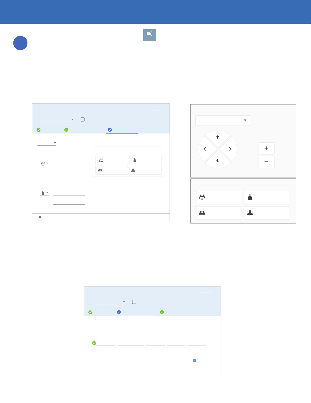
To add Camera Presets, press the Camera icon,
CAMERA
, on Mira Connect and select a camera from the camera pull
down box on Mira Connect. Next, manually posion the camera using Mira Connect (or use the remote control
capabilies from Mira Portal) to the desired locaon and zoom level.
Next, edit the equipment in Mira Portal and navigate to the Camera Presets tab. Select the desired camera from
the pull down list, and click ADD PRESET. Select an icon, and enter a preset name and oponal descripon.
Once the camera is in the desired locaon, press SAVE PRESET to save that camera posion. Repeat the process for
saving mulple camera presets. When nished saving presets, click Update Equipment to store the preset
informaon and update the user interface on Mira Connect. Presets will appear in Mira Connect as shown on the
right of the following gure.
Note that presets won’t appear on Mira Connect unl Update Equipment has been selected on Mira Portal.
Camera Posioning Speed Control
VISCA cameras from various manufacturers have dierent sensivies to VISCA camera move commands - some move
quickly and some move slowly. To account for these dierences, Mira Portal supports seng camera movement speeds
for pan, lt, and zoom both when the movement buon is tapped and when it is held. To congure these sengs,
navigate to the Camera Conguraon tab in Mira Portal and increase or decrease the moon speed as shown in the
following gure. Pan speed can be adjusted from 1 to 24 (fastest), lt speed from 1 to 20 (fastest), and zoom speed from
1 to 7 (fastest).
4
Step
Pan/Tilt
Select camera:
Zoom
WIDE VIEW
Full Room View
Camera presets:
Smaller Meeting
Front of Room
One on One
TABLE END CLOSE UP VIEW
PRESENTER
FRONT OF ROOM
Update Equipment
CONNECTION CAMERA CONFIGURATION CAMERA PRESETS
Equipment Type*
Simulate equipment
Universal VISCA Camera
Camera
These preset items will appear on Mira Connect.
Icon Label
WIDE VIEW
WIDE VIEW
ADD PRESET
SAVE POSITIONREMOVE
View of the Room
View of the Room Front of Room
Front of Room
Camera Presets Preview
Camera presets:
After adding a preset, save the current camera position
to that preset with the “Save Position” button.
Descripon (Oponal)
Label
PRESENTER
PRESENTER
SAVE POSITIONREMOVE
Front of Room
Descripon (Oponal)
UPDATE EQUIPMENTCANCEL
Didn’t find your equipment? Request it!
Smaller Meeng One on One
TABLE END CLOSE UP VIEW
Questions about Universal VISCA Camera?
See the integration guide.
i
Update Equipment
CONNECTION CAMERA CONFIGURATION CAMERA PRESETS
Equipment Type*
Simulate equipment
Universal VISCA Camera
ADD DAISY-CHAINED RS-232 CAMERA
Camera 11 8 8
Add any VISCA cameras that are daisy-chained via RS-232
Invert Pan Controls
Camera ID * Camera Name * Pan Speed *
3
Pan Speed (Slow) *
3
Tilt Speed (Slow) *
1
Zoom Speed (Slow) *
Tilt Speed *
3
Zoom Speed *
UPDATE EQUIPMENTCANCEL
Didn’t find your equipment? Request it!
3
Mira Connect Integraon with PTZ Cameras
The rst row of speed controls aect when the pan, lt, or zoom buon is pressed and held. Default values are Pan
Speed: 8, Tilt Speed: 8, and Zoom Speed: 3. The second row of speed controls aect when the pan, lt, or zoom buon is
tapped. Default speed values are Pan Speed (Slow): 3, Tilt Speed (Slow): 3, and Zoom Speed (Slow): 1.
To increase the speed of camera movement, increase the speed value. To decrease the speed of movement - mostly used
when tapping the buon once moves the camera too much - lower the speed number.
Invert Pan Controls
If you’d like to reverse le and right camera movements when using Mira Connect (highlighted
in the gure on the right) when the camera navigaon buons are pressed on Mira Connect,
enable the invert pan control opon for each camera in your system.
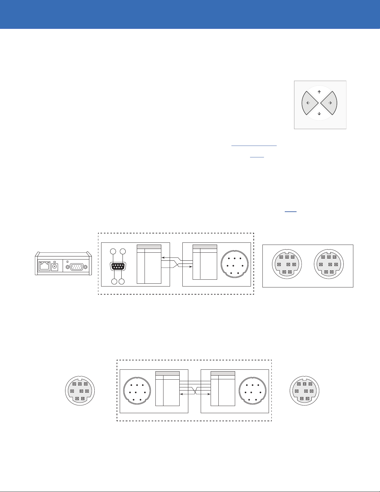
Connecon Interface
Network connecon using default TCP port 4999 with a Global Caché IP2SL interface, or a dierent user specied port for
direct Ethernet control for cameras that support Ethernet control. See our integraon guide for conguring the IP2SL.
When using the Global Caché IP2SL interface for serial control, use Global Caché’s iHelp program to discover the IP2SL’s
IP address, then browse into the device to set the desired stac IP address. The Global Caché IP2SL with PoE (part
number 151.0010.001) is available as an accessory from Aveo Systems.
Ensure the baud rate on the Global Caché IP2SL matches the baud rate congured on the camera. Default RS-232 sengs
for most PTZ Camera are 9,600 baud, 8 data bits, no parity, 1 stop bit, no ow control.
Use a straight-through RS-232 cable that you provide as shown in the following gure to connect the Global Caché IP2SL
to the RS-232 IN connector on the camera. An example cable that is known to work is available here.
Global Cache IP2SL
Pin 1Pin 5
Pin 9 Pin 6
Pin Signal
1
2 RX
3 TX
4
5 Ground
6
7
8
9
DB9 Female
DB9 Male
DB9 Female
Pin Signal
1
2
3 TX
4 Ground
5 RX
6
7
8
DIN Male
Straight-Through RS-232 Control Cable DB9F - VISCA 8-pin DIN Male
RS-232 Connector
is DB9 Male
1 2
3 4 5
6 7 8
RS-232 connector
is 8-pin DIN Female
Equipment to be Controlled
12
345
6
78
12
345
6
78
IN OUT
VISCA
RS-232
Mulple cameras are supported on a single RS-232 interface by daisy-chaining the RS-232 OUT port of one camera to the
RS-232 IN port on the next camera. All cameras must have unique IDs ranging from 1 to 7. Typically the camera ID’s are
created automacally by the cameras as they communicate over RS-232. To connect mulple cameras using the VISCA in
and out connecons, create or purchase a cable with the following pin-out.
Tested Systems
ClearOne Unite 150 and 200 cameras, Sony EVI-D70, HuddleCam HC10X, HuddleCam HC3X.
Pan/Tilt
Pin Signal
1
2
3 TX
4 Ground
5 RX
6
7
8
DIN Male
DB9 Male
DB9 Female
Pin Signal
1
2
3 TX
4 Ground
5 RX
6
7
8
DIN Male
RS-232 Control Cable VISCA 8-pin DIN Male - VISCA 8-pin DIN Male
1 2
3 4 5
6 7 8
1 2
3 4 5
6 7 8
RS-232 connector
is 8-pin DIN Female
RS-232 connector
is 8-pin DIN Female
VISCA CameraVISCA Camera
12
345
6
78
12
345
6
78
INOUT
4
Mira Connect Administrators Guide
See the Mira Connect Administrators Guide for addional informaon about using Mira Portal to set up Mira Connect.
Informaon about integrang specic cameras is summarized below.
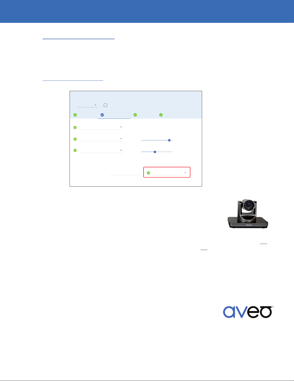
Zoom Rooms Integraon
If integrang one or more VISCA cameras with Zoom Rooms video conferencing systems, associate the VISCA camera(s)
with the Zoom Rooms using the Zoom Rooms CAMERA & AUDIO tab as shown in the following gure.
See the Zoom Room Integraon guide for addional informaon about seng up a Zoom Rooms system with Mira
Connect.
Update Equipment
UPDATE EQUIPMENTCANCEL
CONNECTION CAMERAS & AUDIO VIDEO INPUTS
Equipment Type*
Simulate equipment
Zoom Rooms
USB Camera
Camera Names and Control
A camera can be given a name that is more meaningful to a user, such as “Room Overview” or“Document Camera”. Selecting a VISCA camera
interface from the list will provide pan, tilt, and zoom controls.
OPTIONS
Build-in Input (Line In) Volume
Microphone
Built-in Output (Internal Speakers)
Unite 150 Front of Room Front of Room
Camera Name VISCA Camera Control
Speaker
Volume
Specic Camera Informaon
ClearOne Unite 200
The ClearOne Unite 200, when controlled over its Ethernet interface, uses port 5678 by
default. This port can be changed from the camera’s web interface. The default IP address
of the ClearOne Unite 200 is 192.168.100.88 with username and password “admin” and
“admin”, respecvely.
When controlled over its Ethernet interface, the camera properly supports all camera posioning, however it does not
support power on and o commands. Powering o the room using Mira Connect will not put the camera into standby
mode as the power state will remain unchanged.
If the camera is powered o via an IR remote, it cannot be powered back on via Ethernet control. If the Unite 200
camera is powered on via its IR remote, the camera’s Ethernet interface is reset upon power up, causing Mira Connect
to re-establish network communicaon. Upon power up, camera control features are briey unavailable while Mira
Connect automacally re-establishes the network connecon.
When controlled over its RS-232 interface, the ClearOne Unite 200 camera correctly supports power on and o
commands and supports going into and out of standby mode.
DS-11001-021
Version 2019_10_24
Specicaons subject to change without noce. Aveo Systems and the Aveo logo are registered trademarks.
All other trademarks are the property of their respecve owners.
For more informaon please contact our Sales Department at sales@aveosystems.com.
About Aveo Systems
Aveo Systems is a leading provider of intuive and easy-to-use soluons for audio, video, and
collaboraon, improving how systems are used and managed by customers world-wide.
R
SYSTEMS
Mira Connect Integraon with PTZ Cameras
This manual suits for next models
2


