Avia Propeller AV-723-1-D-C-F-R Specification sheet

O
OP
PE
ER
RA
AT
TI
IO
ON
N
A
AN
ND
D
I
IN
NS
ST
TA
AL
LL
LA
AT
TI
IO
ON
N
M
MA
AN
NU
UA
AL
L
REVERSIBLE HYDRAULICALLY CONTROLLED
VARIABLE PITCH PROPELLERS
(CONSTANT SPEED)
AV-723-1-D-C-F-R(P)
AV-725-1-E-C-F-R(P), (W)
AV-803-1-E-C-F-R(W)
AV-80 -1-E-C-F-R(W)
AV-8 -1-E-C-F-R(G), (P), (W)
Document number:
E
EN
N-
-1
13
32
20
0
ATA 61-10-20
Issue 4: October 06, 2017
Revision: March 4, 2019
The technical content of this document is approved
under authority of DOA No. EASA.21J.072.
Avia Propeller s.r.o., Beranových 65/666, 199 00 Praha 9 - Letňany, CZECH REPUBLIC

FOR OPERATORS AND SERVICE STAFF
THE PROPELLER IS A VITAL COMPONENT OF THE AIRCRAFT. IT IS VERY
IMPORTANT TO FOLLOW ALL INSTALLATION INSTRUCTIONS AND INSPECTION
PROCEDURES DESCRIBED IN THIS MANUAL.
FAILURE TO FOLLOW
THE INSTRUCTIONS AND PROCEDURES DESCRIBED IN THIS MANUAL
MAY CAUSE DAMAGE TO THE PROPELLER RESULTING IN AN AIRCRAFT
ACCIDENT.
ALL PROCEDURES DESCRIBED IN THIS MANUAL SHOULD BE PERFORMED
ONLY BY QUALIFIED PERSONNEL.
ANY ACTIVITIES BEYOND THE SCOPE OF THIS MANUAL TO BE PERFORMED
ONLY BY A PERSON TRAINED AND AUTHORIZED BY AVIA PROPELLER.
ALWAYS USE THE LATEST REVISION OF THIS MANUAL. THE LATEST
REVISION OF THIS MANUAL IS AVAILABLE FREE OF CHARGE AT
WWW.AVIAPROPELLER.COM.
VISIT WWW.AVIAPROPELLER FOR SERVICE BULLETINS, SERVICE
LETTERS AND SERVICE ADVISORIES THAT MAY BE ASSOCIATED WITH
THE PROPELLERS IN THIS MANUAL.
T
TH
HA
AN
NK
K
Y
YO
OU
U
F
FO
OR
R
C
CH
HO
OO
OS
SI
IN
NG
G
A
AV
VI
IA
A
P
PR
RO
OP
PE
EL
LL
LE
ER
R
P
PR
RO
OD
DU
UC
CT
T
Properly maintained it will give you many years of reliable service.

OPERATION AND INSTALLATION MANUAL
EN-1320
TABLE OF CONTENTS Page
LIST OF REVISIONS . . . . . . . . . . . . . . . . . . . . . . . . . . . . . . . II - 1
LIST OF EFFECTIVE PAGES . . . . . . . . . . . . . . . . . . . . . . . . . III-1
1. AIRWORTHINESS LIMITATIONS . . . . . . . . . . . . . . . . . . . . . . 1 - 1
2. GENERAL . . . . . . . . . . . . . . . . . . . . . . . . . . . . . . . . . . . . . . . . 2 - 1
3. MODEL DESIGNATION . . . . . . . . . . . . . . . . . . . . . . . . . . . . . 3 - 1
4. DESIGN AND OPERATION INFORMATION . . . . . . . . . . . . . 4 - 1
5. INSTALLATION AND OPERATION INSTRUCTION . . . . . . . . 5 - 1
6. INSPECTIONS . . . . . . . . . . . . . . . . . . . . . . . . . . . . . . . . . . . . . 6 - 1
7. MAINTENANCE . . . . . . . . . . . . . . . . . . . . . . . . . . . . . . . . . . . . 7 - 1
8. TROUBLE SHOOTING . . . . . . . . . . . . . . . . . . . . . . . . . . . . . . 8 - 1
9. SHIPPING AND STORAGE . . . . . . . . . . . . . . . . . . . . . . . . . . . 9 - 1
10. TOOLING . . . . . . . . . . . . . . . . . . . . . . . . . . . . . . . . . . . . . . . . . 10 - 1
11. DRAWINGS AND PARTLISTS . . . . . . . . . . . . . . . . . . . . . . . . 11 - 1
12. PROPELLER CONTROL SYSTEM
(Installation with Jihostroj LUN-Series Governor) . . . . . . . . . . . 12 - 1
61-10-20
TABLE OF CONTENT Page I-1
2017
-
10
-
06

EN-1320
OPERATION AND INSTALLATION MANUAL
LIST OF REVISIONS
Rev.No. Page Revised Page Date
R-106/17 All 2017-10-06
R-71/18 Cover, II-1, III-1, 5-14 2018-07-27
R-23/19 Cover, II-1, III-1, 5-2, 5-14, 12-6, 12-10, 12-11, 12-16, 12-37 2019-03-04
REVISION R-23/19 - SUMMARY
Aeroshell Grease 22 added as replacement of Aeroshell Grease 5 and 6 throughout the manual.
Typo correction.
61-10-20
LIST OF REVISIONS Page II-1
201
9
-
03
-
04

OPERATION AND INSTALLATION MANUAL
EN-1320
LIST OF EFFECTIVE PAGES
Page Date Page Date Page Date
Cover 2019-03-04 6-10 2017-10-06 12-8 2017-10-06
I-1 2017-10-06 6-11 2017-10-06 12-9 2017-10-06
II-1 2019-03-04 6-12 2017-10-06 12-10 2019-03-04
III-1 2019-03-04 6-13 2017-10-06 12-11 2019-03-04
6-14 2017-10-06 12-12 2017-10-06
1-1 2017-10-06 7-1 2017-10-06 12-13 2017-10-06
2-1 2017-10-06 7-2 2017-10-06 12-14 2017-10-06
2-2 2017-10-06 7-3 2017-10-06 12-15 2017-10-06
3-1 2017-10-06 7-4 2017-10-06 12-16 2019-03-04
3-2 2017-10-06 8-1 2017-10-06 12-17 2017-10-06
4-1 2017-10-06 8-2 2017-10-06 12-18 2017-10-06
4-2 2017-10-06 8-3 2017-10-06 12-19 2017-10-06
4-3 2017-10-06 9-1 2017-10-06 12-20 2017-10-06
5-1 2017-10-06 10-1 2017-10-06 12-21 2017-10-06
5-2 2019-03-04 11-1 2017-10-06 12-22 2017-10-06
5-3 2017-10-06 11-2 2017-10-06 12-23 2017-10-06
5-4 2017-10-06 11-3 2017-10-06 12-24 2017-10-06
5-5 2017-10-06 11-4 2017-10-06 12-25 2017-10-06
5-6 2017-10-06 11-5 2017-10-06 12-26 2017-10-06
5-7 2017-10-06 11-6 2017-10-06 12-27 2017-10-06
5-8 2017-10-06 11-7 2017-10-06 12-28 2017-10-06
5-9 2017-10-06 11-8 2017-10-06 12-29 2017-10-06
5-10 2017-10-06 11-9 2017-10-06 12-30 2017-10-06
5-11 2017-10-06 11-10 2017-10-06 12-31 2017-10-06
5-12 2017-10-06 11-11 2017-10-06 12-32 2017-10-06
5-13 2017-10-06 11-12 2017-10-06 12-33 2017-10-06
5-14 2019-03-04 11-13 2017-10-06 12-34 2017-10-06
5-15 2017-10-06 11-14 2017-10-06 12-35 2017-10-06
6-1 2017-10-06 11-15 2017-10-06 12-36 2017-10-06
6-2 2017-10-06 11-16 2017-10-06 12-37 2019-03-04
6-3 2017-10-06 12-1 2017-10-06 12-38 2017-10-06
6-4 2017-10-06 12-2 2017-10-06 12-39 2017-10-06
6-5 2017-10-06 12-3 2017-10-06 12-40 2017-10-06
6-6 2017-10-06 12-4 2017-10-06 12-41 2017-10-06
6-7 2017-10-06 12-5 2017-10-06 12-42 2017-10-06
6-8 2017-10-06 12-6 2019-03-04
6-9 2017-10-06 12-7 2017-10-06
61-10-20
LIST OF EFFECTIVE PAGES Page III-1
201
9
-
03
-
04

EN-1320
OPERATION AND INSTALLATION MANUAL
1.0. AIRWORTHINESS LIMITATIONS
This Airworthiness Limitations Section is EASA approved in accordance with Part 21A.31(a)(3)
and CS-P40(b) and 14 CFR Part 35.4 (A35.4). Any change to mandatory replacement times,
inspection intervals and related procedures contained in this section must also be approved.
The Airworthiness Limitations Section is FAA approved and specifies maintenance required
under §§ 43.16 and 91.403 of the Federal Aviation Regulations unless an alternate program
has been FAA approved.
1.1. Service Life Limits
1) The life limit should be established for certain part of the propeller assembly. This limit
requires the replacement of such part after a specified number of hours of operation (TSN,
Time Since New).
2) This section summarizes the life limited parts of propellers in this manual.
3) The blade life limit is not affected whether or not the de-icing components are installed.
4) Below mentioned life limits of the parts apply to all of propeller models and propeller-aircraft-
engine combinations, unless stated otherwise.
5) Life limited parts of AV series propellers for turbine engines
Part Life limit
Blade . . . . . . . . . . . . . . . . . 12 000 hours
Hub . . . . . . . . . . . . . . . . . . 12 000 hours
Bearing race . . . . . . . . . . . 12 000 hours
Blade bushing . . . . . . . . . . 12 000 hours (if applicable)
Cylinder . . . . . . . . . . . . . . . 12 000 hours (if applicable)
61-10-20
AIRWORTHINESS LIMITATIONS Page 1-1
2017
-
10
-
06

OPERATION AND INSTALLATION MANUAL
EN-1320
2.0. GENERAL
2.1. Statement of Purpose
This publication provides operation, installation and line maintenance information on the Avia
hydraulically controlled, variable pitch AV series propellers with aluminum blades. All models
are equipped with reverse and feathering capability.
In addition to the propeller assembly, the information on governing system with Jihostroj
LUN-Series governor is also adressed in this manual.
Installation, removal, operation and trouble shooting data is included in this publication.
However, the airplane and engine manufacturer's manuals should be used in addition to this
manual.
2.2. Overhaul
For the list of TBO limits of all Avia propellers refer to latest issue of Avia Service Bulletin No.1
available at Avia Propeller website at www.aviapropeller.com.
The overhaul is periodic process performed at specific intervals in which the propeller is
disassembled and inspected. Damaged parts are repaired or replaced. All sealing elements are
replaced. Corrosion preventive coatings of the parts are renewed. Propeller is reassembled,
adjusted and balanced.
The overhaul interval is usually referred to as Time Between Overhaul (TBO).
The TBO limit is based on operation limit expressed in hours of operation and on calendar limit
expressed in calendar months. The overhaul should be accomplished if one of this limit is
acquired, whichever occurs first.
The overhaul shall be accomplished only by Avia Propeller or authorized service station in
accordance with latest revision of the Overhaul manual mentioned in section „Related
documents“ in this chapter.
2.3. Related Documents
1) Avia Manual EN-1291 (61-10-91) - Overhaul Manual
2) Avia Manual EN-1370 (61-10-70) - Overhaul Manual for Metal Blades
3) Avia Service Bulletin No.1
Includes an overhaul intervals of all Avia propellers. Available on Avia website at
www.aviapropeller.com.
4) Other Avia service documents (Service Bulletins, Service Letters, Service Advisories)
which may relate to propellers in this manual are available on Avia website at
www.aviapropeller.com.
61-10-20
GENERAL Page 2-1
2017
-
10
-
06

EN-1320
OPERATION AND INSTALLATION MANUAL
2.4. Dimensions
All dimensions in this manual are in millimeters with equivalent in inches.
All temperature units in this manual are in Celsius grades with equivalent in Fahrenheit grades.
All pressure units in this manual are in megapascals with equivalent in pounds per square inch.
2.5. Part Replacement
Basically, only some outside mounted parts, such as propeller-to-engine o-ring, de-icing
cables and some other de-icing components, some fasteners, may be replaced in the field
by the user. Some other parts may be replaced in the field only by person trained and
authorized by Avia Propeller.
Contact the Avia Propeller for information on part replacement. Parts that did not come
through the manufacturer's quality control system will void the warranty and may render
the propeller unairworthy.
61-10-20
GENERAL Page 2-2
2017
-
10
-
06

OPERATION AND INSTALLATION MANUAL
EN-1320
3.0. MODEL DESIGNATION
3.1. Hub designation
A
V
-
72
5
-
1
-
E
-
C
-
F
-
R
(W)
-
( )
1
2
3
4
5
6
7
8
9
10
11
1 Avia Propeller (manufacturer)
2 V= Variable pitch propeller
3Type of blade shank
4 Number of blades
5 Consecutive number of series
6 Code for propeller flange
D = ARP 502, six mounting studs 1/2“-20UNF, two dowel pins,
pitch circle 4.0 inch (101,6 mm)
E= ARP 880, eight mounting studs 9/16“-18UNF, two dowel pin holes,
pitch circle 4.25 inch (107,95 mm)
7 Letter for counterweights
C= Counterweights for pitch change forces to increase pitch
8 Letter for feathering
F= Feathering capability
9 Letter for reverse
R= Reverse capability
10 Code for reverse system
(G) = Reverse system Garrett TPE-331-( )
(P) = Reverse system Pratt&Whitney PT6A-( )
(W) = Reverse system Walter M601-( ) / GE H-Series
11 Code for design changes
Small letter: Modification not affecting interchangeability
Capital letter: Modification restricting or excluding interchangeability
-R(W) blank = overspeed governor for 2080 rpm engines
-R(W)-A = overspeed governor for 1950 rpm engines
61-10-20
MODEL DESIGNATION Page 3-1
2017
-
10
-
06

EN-1320
OPERATION AND INSTALLATION MANUAL
3.2. Blade Designation
CFR ( )
230
-
433
( )
1 2 3
4 5
1 Code for pitch change pin position
CFR = pitch change pin for feathering and reverse ; pitch change forces
to increase pitch
2 Sense of rotation
blank = right-hand, tractor
3 Propeller diameter in cm
4Consecutive number of basic type
(includes design configuration and aerodynamic data)
5 Code letter for design changes
Small letter: Modifications not affecting interchangeability
Capital letter: Modifications restricting or excluding interchangeability
3.3. The complete propeller designation is a combination of both hub and blade designations,
separated by a slash mark ; for instance AV-725-1-E-C-F-R(W) / CFR230-433a.
3.4. The hub-serial No. starts with the year of manufacture. All records of the propeller are
registered in respect to this number.
3.5. The propeller for a certain aircraft-engine combination is always defined according the
hub- blade- spinner combination. For the actual blade settings, depending on the aircraft
model, the propeller logbook must be considered.
61-10-20
MODEL DESIGNATION Page 3-2
2017
-
10
-
06

OPERATION AND INSTALLATION MANUAL
EN-1320
4.0. DESIGN AND OPERATION INFORMATION
The variable pitch propeller consists of the following main groups:
- Hub with blade bearing
- Pitch change mechanism
- Propeller blades
- Counterweights
- Spinner
- Propeller governor
- Electrothermal de-icing system
4.1. Hub
The one-piece hub is made from forged or milled aluminum alloy with the outer surface
shot-peened and anodized.
Propellers with thread-type blades
The blade bearings are special designed ball bearings, whereas the balls act as split retainers
in order to hold the blades in the hub, creating an increased safety factor against blade loss.
The outer bearing race is a one-piece part and pressed into the hub, while the inner race is split
and installed on the blade shank. The blade preload is adjusted by the thickness of plastic
shims. Blade and bearing are held in the hub by a retention ring.
Propellers with threadless-type blades
The inner bearing race is located on the blade bushing, whereas the blade are screwed into the
bushing and tightened by the clamp. The outer bearing race is a one-piece part and pressed
into the hub. The blade preload is adjusted by the prestressing nut, which holds the blade
bearing and blade in the hub.
The pitch change of the blades is obtained with a pin in the blade shank or in the blade bushing
face. A plastic block connects the blade with the piston and the axial movement of the servo
piston turns the blades. On the front piston the return spring and the sleeve, which acts as high
(low) pitch stop, are installed.
The inner part of the hub is used as the cylinder for the pressure oil. This arrangement allows a
simple and lightweight design. The front spinner support is used to have the balance weights
installed.
On the Walter Reverse System the pitch change cylinder is installed on the hub front part.
4.2. Pitch Change Mechanism
The pitch change mechanism of the blades is obtained with a pin in the blade shank or on the
blade bushing. A plastic block connects the blade with the piston extension and the axial
movement of the servo piston turns the blades. On the front piston guide the return spring is
installed enabling feathering. With the Walter System the reverse system is dual acting,
whereas feathering is achieved by using oil pressure.
The hydraulic pitch change mechanism contains a piston. In the normal operating range the
pitch change piston moves between full feathering and the hydraulic low pitch stop. In the beta
range the hydraulic low pitch stop moves via the beta linkage until the needed negative thrust
is reached.
61-10-20
DESIGN AND OPERATION INFORMATION Page 4-1
2017
-
10
-
06

EN-1320
OPERATION AND INSTALLATION MANUAL
4.2.1. For Pratt&Whitney Application
Outside the hub there are check nuts and in the inner part of the hub there are 3 stop nuts.
High pitch/feathering can be set by turning the check nuts. Low pitch can be set by turning the
internal stop nuts The full reverse stop is not adjustable in the field.
4.2.2. For Garrett Application
Outside the hub are two check nuts. High pitch feathering stop can be adjusted by turning the
check nuts. The beta tube is installed in the guide rod. Due to turning the beta tube inside or
outside, the hydraulically low pitch stop can be adjusted.
The beta tube is secured by the screw AN3H-13A and the stop nut MS 20364-1032A.
Put on both sides washers AN 960-10.
4.2.3. For Walter Application
All stops are internal and can not be changed. No adjustment is necessary, because during
manufacturing all pitch settings were made.
4.3.
Propeller Blades
Propeller blades are made from aluminium alloy. They are turning in the ball bearings with one
set of balls in the propeller hub. Connection with the pitch change mechanism is made through
plastic pitch change blocks installed on the pins in the blade shank (threadless-type blades) or
on the blade bushing face (thread-type blades).
Propeller blades can be designed with counterweights installed on the blade shank.
Leading edges of the blades can be protected with polyurethane guards for mechanical
damages prevention.
4.4. Counterweights
Propellers may by equipped with counterweights on the blade shanks or as the part of the hub.
If governor supplied oil is lost during operation, force from counterweights move the blades to
high pitch and feather to prevent propeller overspeed.
4.5. Spinner
The spinnerdome is made from fiber reinforced composite or spinformed aluminum alloy. The
bulkhead is spinformed or truncated aluminium alloy.
If the spinner dome has no integrated stiffeners, then the front support is installed as part of the
hub. Filler plates increase the stiffness of the dome on the cutouts for the blades. The dome is
mounted on the supports by means of screws.
61-10-20
DESIGN AND OPERATION INFORMATION Page 4-2
2017
-
10
-
06

OPERATION AND INSTALLATION MANUAL
EN-1320
4.6. Propeller Governor
4.6.1. See Avia Manual No. E-1707 for Avia P-W( ) Series governors.
4.6.2. See Woodward Manual for:
Garret TPE-331-( ): No. 33091-( )
Pratt and Whitney PT6A: No. 33163-( ) Primary
No. 33048-( ) Overspeed
4.6.3. See Walter Manual for:
Walter M601-Series: No. 098 2302 Chapter 61.
4.6.4. See Propeller Control System chapter in this manual for information on propeller control system
associated with Jihostroj LUN-series governors.
4.7. Electrothermal De-icing System
The propeller may have electrical or liquid de-icing systems installed. The de-icer boots are
bonded onto the blades as usual. The rest of the electrical system is equal to existing
components, with slip ring and wire harness.
4.8. Oil
The propellers operate with the oil supplied from engine lubricating system. Refer to engine
manufacturer´s manual for more information.
61-10-20
DESIGN AND OPERATION INFORMATION Page 4-3
2017
-
10
-
06

EN-1320
OPERATION AND INSTALLATION MANUAL
5.0 INSTALLATION AND OPERATION INSTRUCTION
CAUTION 1: DO NOT USE THE SPINNER BULKHEADS TO SUPPORT THE WEIGHT OF THE
PROPELLER ASSEMBLY, OTHERWISE THEY COULD BE IRREPARABLY
DAMAGED.
CAUTION 2: DO NOT USE THE BLADES TO SUPPORT THE WEIGHT OF THE PROPELLER
ASSEMBLY, OTHERWISE THEY COULD BE DAMAGED.
CAUTION 3: TAKE CARE NOT TO DAMAGE THE DE-ICERS COMPONENTS (AS
APPLICABLE) FROM THE SLINGS WHEN LIFTING THE PROPELLER.
CAUTION 4: DO NOT STAND THE PROPELLER ON THE BETA RING OTHERWISE IT MAY
BE DAMAGED LEADING TO INCORRECT FUNCTION OF THE BETA SYSTEM.
REMOVE THE SHIPPING PLUG FROM PROPELLER MOUNTING FLANGE
AFTER IS HANGED ON THE CRANE FOR INSTALLING ON ENGINE.
WARNING: CLEANING AGENTS ARE FLAMMABLE AND TOXIC TO THE SKIN, EYES AND
RESPIRATORY TRACT. SKIN AND EYE PROTECTION IS REQUIRED. AVOID
PROLONGED BREATHING OF VAPORS. USE IN WELL VENTILATED AREA.
FOLLOW MANUFACTURER´S SAFETY PRECAUTIONS.
5.1.1 All propellers of these designs are only suitable for installation on flange type engines. The
code for the flange type can be seen from the model designation (see Chapter 3).
5.1.2 The described propellers are usually installed on the engine with the blades in feathering position.
5.2 Electrical propeller de-icing may be used optionally. Observe Aircraft Flight Manual for the
limitations during ground operation in order to avoid damage of the de-ice boots (overheating).
5.3 Spinner Dome Removal
a) Propeller AV-725 with metal spinner dome
Remove all screws attaching the spinner dome to the rear bulkhead and to the stiffeners
at the blade cutouts, and remove the spinner dome from the propeller. Do not remove
the screws attaching the stiffeners at the blade cutouts to the rear bulkhead.
NOTE: Do not remove the screws attaching the front bulkhead inside the spinner dome
(the screws approx. at half the height of the spinner dome). Remove the spinner
dome and front bulkhead as assemly.
If the screws attaching the spinner dome to the front bulkhead were removed by mistake,
remove the spinner dome and the front bulkhead from the propeller. See marking 1 to 5
inside the spinner dome (near the blade cutouts) and on the front bulkhead (near the rim)
and reinstall the front bulkhead into the spinner dome. Be sure that all screws are properly
tightened.
NOTE: Information on the screws attaching the spinner dome to the front bulkhead is not
applicable to models, where the front bulkhead is riveted to the spinner dome (no
screws in the area of the front bulkhead).
b) Propeller AV-725 with composite spinner dome and all other propeller models
Remove all existing screws attaching the spinner dome to the rear and front bulkheads and
to the stiffeners in the blade cutouts, and remove the spinner dome from the propeller. Do
not remove the screws attaching the stiffeners at blade cutouts to the rear bulkhead.
61-10-20
INSTALLATION AND OPERATION INSTRUCTION Page 5-1
2017
-
10
-
06
OPERATION AND INSTALLATION MANUAL
EN-1320
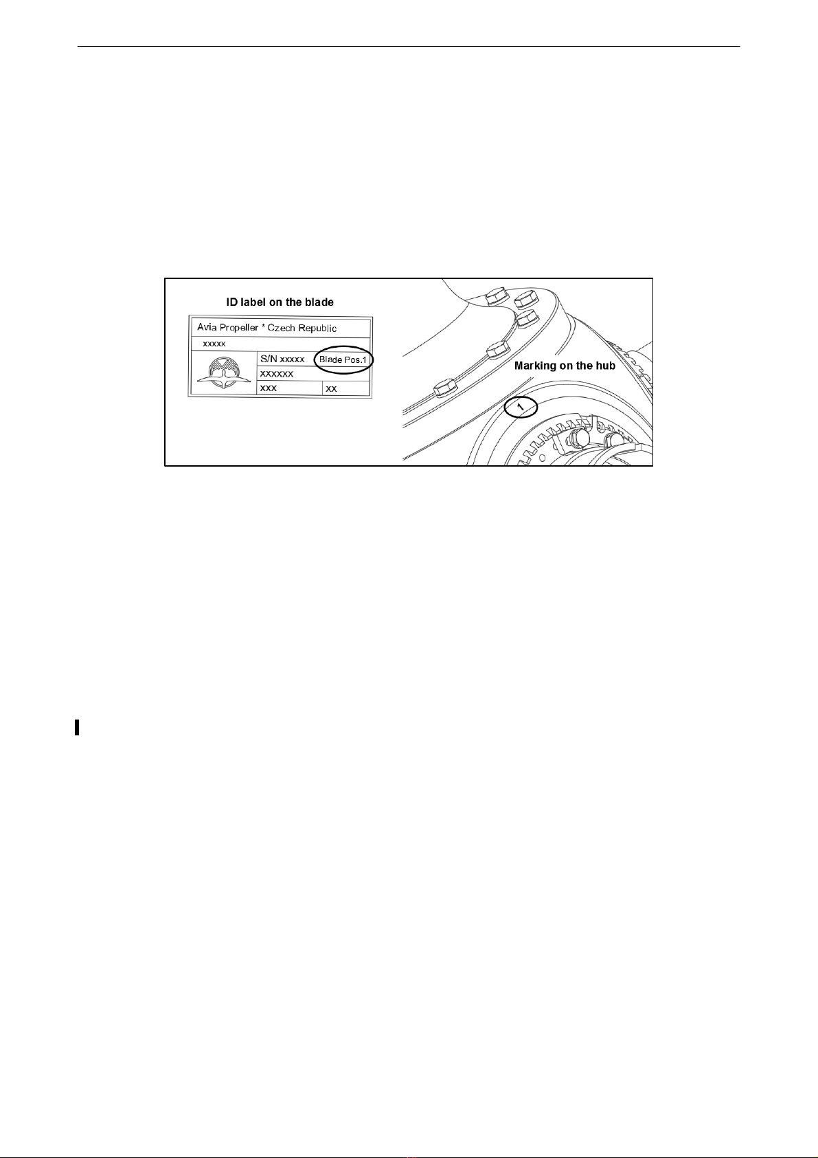
5.4 Installing the Blades into the Hub (except model AV-844)
a) Observe the label located on the blade. When installing the blade into the hub, make sure
that position number on the label corresponds with the number stamped on the hub, at
the bushing where the blade will be installed. See Figure 5-1.
CAUTION: IT IS IMPORTANT TO INSTALL THE BLADES INTO THEIR MATCHING
BUSHINGS IN THE HUB. OTHERWISE VIBRATIONS MAY OCCUR,
RESULTING IN DAMAGE TO THE ENGINE.
FIGURE 5-1
b) Check that o-ring is installed on the blade shank. See Figure 5-2. This o-ring is usually
installed on the shank when the blades are delivered for initial instalation.
NOTE: The o-ring prevents moisture to get into the blade bushing. Otherwise corrosion
of the blade and blade bushing may occur. This can cause the blade and blade
bushing will be scrapped at overhaul.
c) Make sure that blade shank and inside of the blade bushing are clean and dry. Clean with
lint-free cloth, either dry or lightly dampened in MEK, as necessary.
CAUTION: AVOID CONTACT OF THE O-RING WITH CLEANING SOLVENT.
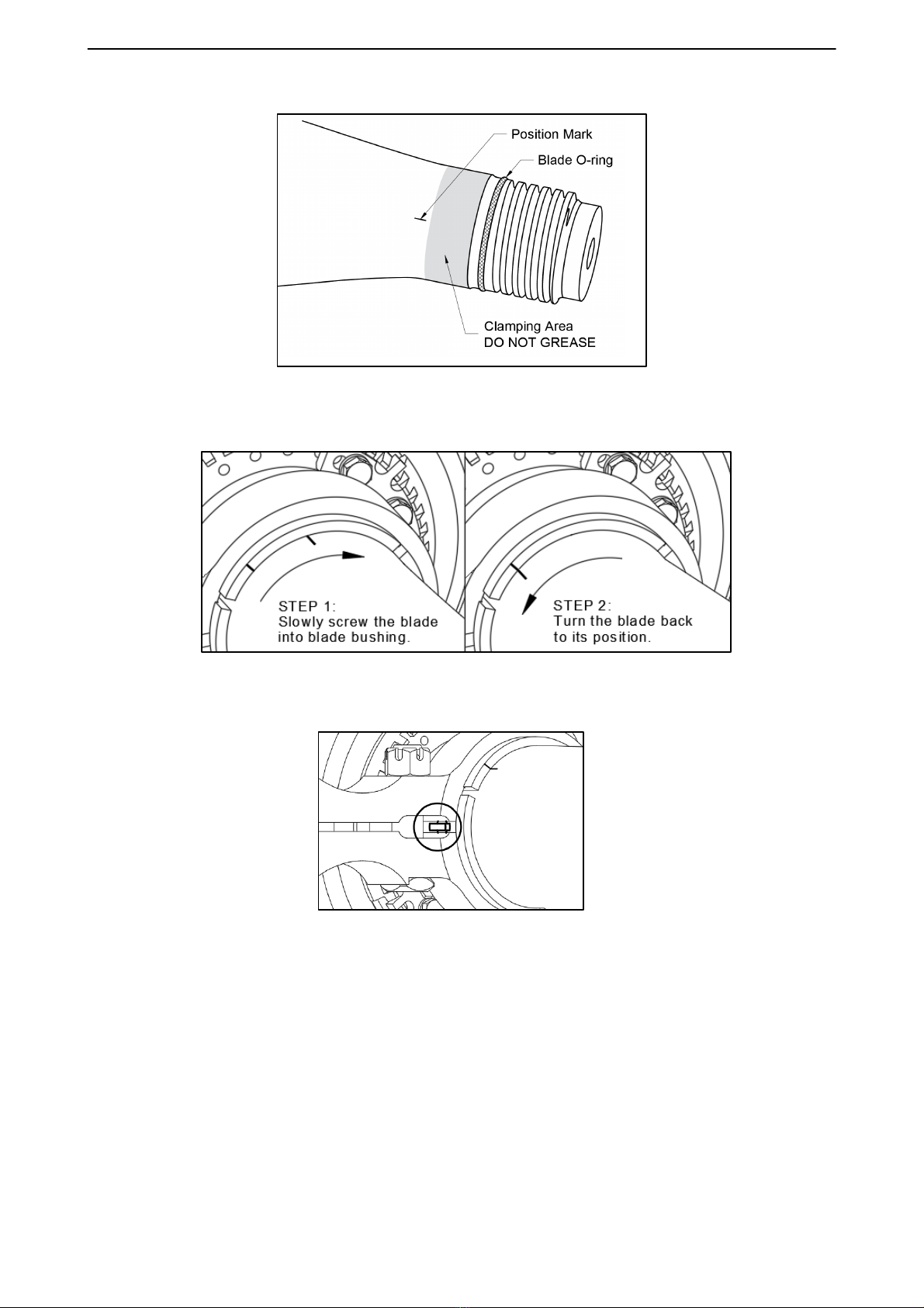
d) Lightly grease the blade thread with Aeroshell Grease 5, 6 or 22.
CAUTION: DO NOT GREASE THE CLAMPING PORTION OF THE BLADE SHANK,
SEE FIGURE 5-2. IT MAY DECREASE CLAMPING ACTION LEADING
TO CHANGE OF BLADE ANGLE SETTING IN OPERATION.
e) Make sure that the blade clamp is fully released.
f) Slowly screw the blade into blade bushing until is fully screwed in. Then turn the blade
back to align the position mark on the blade with matching mark on the blade bushing.
See Figure 5-3.
g) Position the clamp so that pin in the blade bushing is in center of the gap. See Figure 5-4.
61-10-20
INSTALLATION AND OPERATION INSTRUCTION Page 5-2
201
9
-
03
-
04
EN-1320
OPERATION AND INSTALLATION MANUAL
FIGURE 5-2
FIGURE 5-3
FIGURE 5-4
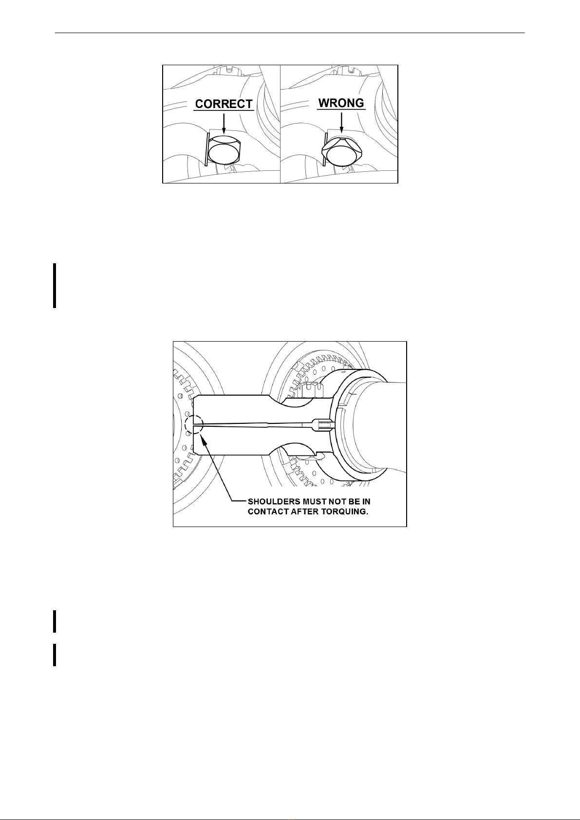
h) Lubricate the screw and nut with graphite grease. Tighten and torque the clamp to
65-70 Nm (48-52 ftlb).
CAUTION: TAKE CARE TO CORRECT SEATING OF THE BOLT HEAD WHEN
TIGHTENING THE CLAMP - SEE FIGURE 5-5. HOLD THE BOLT HEAD
IN CORRECT POSITION WHILE TIGHTENING THE NUT. CHECK
THE CORRECT SEATING OF THE BOLT AFTER TORQUING.
INCORRECTLY TIGHTENED CLAMP WILL CAUSE THE CHANGE OF
BLADE ANGLE SETTING IN OPERATION.
61-10-20
INSTALLATION AND OPERATION INSTRUCTION Page 5-3
2017
-
10
-
06
OPERATION AND INSTALLATION MANUAL
EN-1320
FIGURE 5-5
i) Check the clamp after tightening. The shoulders must not be in contact after tightening to
a specified torque. See figure 5-6.
CAUTION: THE CONTACT BETWEEN CLAMP SHOULDERS AFTER TORQUING
INDICATES THAT THE CLAMP IS NOT PROPERLY TIGHTENED TO
SPECIFIED TORQUE. IT MAY CAUSE THE CHANGE OF BLADE ANGLE
SETTING IN OPERATION.
FIGURE 5-6
j) As necessary, additionally tighten the nut to match the nearest cotter pin hole in the bolt.
Secure the nut with a cotter pin.
CAUTION 1: TURN THE NUT ALWAYS IN TIGHTENING DIRECTION, NEVER
OTHERWISE.
CAUTION 2: THE COTTER PIN MUST NOT BE REUSED. USE ALWAYS A NEW
COTTER PIN WHEN INSTALLING THE BLADE INTO THE HUB.
NOTE: THE CONTACT OF CLAMP SHOULDERS AFTER ADDITIONAL TIGHTENING
IS ACCEPTABLE.
61-10-20
INSTALLATION AND OPERATION INSTRUCTION Page 5-4
2017
-
10
-
06

EN-1320
OPERATION AND INSTALLATION MANUAL
5.5 Electrothermal De-icing System (if installed)
With the screws and toothed washers, connect the cables to matching contacts in the de-icers.
See marking on the cable and on the de-icer.
5.6 Before Installing the Propellers AV-725 and AV-844 Ending in -R(P)
Before installing the propeller on the engine, the beta ring must be pushed forward to allow
access to the propeller mounting flange. See Figures 5-7 and 5-8.
a) Check the distance 46,7±0,2 mm (1.84±0.008 inch) from the beta ring to the propeller
mounting flange.
b) Remove safety wire from the cover caps.
c) Unscrew the cover caps from the hub.
WARNING: BE CAREFUL WHEN REMOVING THE COVER CAP BECAUSE THE SPRING
FORCE UNDER THE CAP.
d) Remove the springs and spring guides from the hub.
e) Push the beta ring toward the propeller mounting flange. See Figure 5-9.
FIGURE 5-7
FIGURE 5-8
61-10-20
INSTALLATION AND OPERATION INSTRUCTION Page 5-5
2017
-
10
-
06

OPERATION AND INSTALLATION MANUAL
EN-1320
FIGURE 5-9
5.7 Before Installing the Propeller Ending in -R(G) on the Engine
Measure the distance “X“ (see Figure 5-10) for the dimension, how far the beta tube must be
turned in (was recorded during previous propeller removal). This is important to set the low
pitch stop.
The O-ring „B“ in the engine flange and the O-ring „A“ on the beta-tube (see Figure 5-10) must
be replaced with every propeller installation.
FIGURE 5-10
61-10-20
INSTALLATION AND OPERATION INSTRUCTION Page 5-6
2017
-
10
-
06

EN-1320
OPERATION AND INSTALLATION MANUAL
5.8 Installing AV-( )-E-( ) Propeller on the Engine
a) Hang the propeller on the crane hoist with a sling. Move the propeller to the engine
mounting flange.
WARNING: MARE SURE THE CRANE HOIST AND SLINGS HAVE A MINIMUM
OF 450 KG (1000 LBS) LIFTING CAPACITY.
CAUTION: TAKE CARE NOT TO DAMAGE DE-ICING COMPONENTS FROM
THE SLINGS, IF APPLICABLE.
b) Make sure the propeller flange and the engine flange are clean.
c) Check that o-ring is installed in the propeller mounting flange.
d) Models ending in -R(W) and -R(G)
Install the o-ring(s) into the engine flange (engine accessory).
e) Align mounting studs and dowel pin holes in the propeller flange with dowel pins and
mounting holes in the engine flange.
f) Carefully slide the propeller onto the engine flange.
NOTE: Depending on installation, there may be not enough space between propeller and
engine to insert mounting nuts with washers onto the studs, if the propeller is fully
slide onto the engine flange. In that case, the propeller to be slide onto the engine
flange in a few steps.
CAUTION: PLEASE NOTE THAT THE PROPELLER SHOULD NOT BE PULLED ONTO
THE ENGINE FLANGE WITH MOUNTING NUTS IN ORDER TO AVOID
DAMAGE TO THE PROPELLER AND TO AVOID SHEARING OFF CHIPS
CAUSING OIL LEAKS ON THE O-RING(S).
g) Make sure that propeller studs, nuts and washer are clean. Apply anti-seize compound per
MIL-PRF-83483 (e.g.LoctiteMoly 50) or Loctite 8012 Moly Paste to threads of studs and
mounting nuts; also to faces of nuts and washers.
h) Make sure that the propeller is fully seated on the engine flange throughout 360 degrees
of rotation. Torque all mounting nuts in the steps and sequences for “E” Flange, as shown
in Figure 5-11.
i) Thoroughly wipe the mounting studs, nuts and washer from anti-seize compound. After the
ground run of the engine, inspect the propeller flange side for any traces of anti-seize
compound on the brush block, slip ring, beta ring, and other parts. Thoroughly wipe before
flight.
CAUTION: ANI-SEIZE COMPOUND ON THE PARTS WILL CAUSE DAMAGE TO
THE PARTS IN OPERATION.
j) Installation with nonself-locking mounting nuts
Safety all mounting nuts with 0,81 mm (0.032 inch) stainless steel safety wire, two nuts per
safety.
61-10-20
INSTALLATION AND OPERATION INSTRUCTION Page 5-7
2017
-
10
-
06
This manual suits for next models
12
Table of contents


