Avid CNC PRO4848 User manual

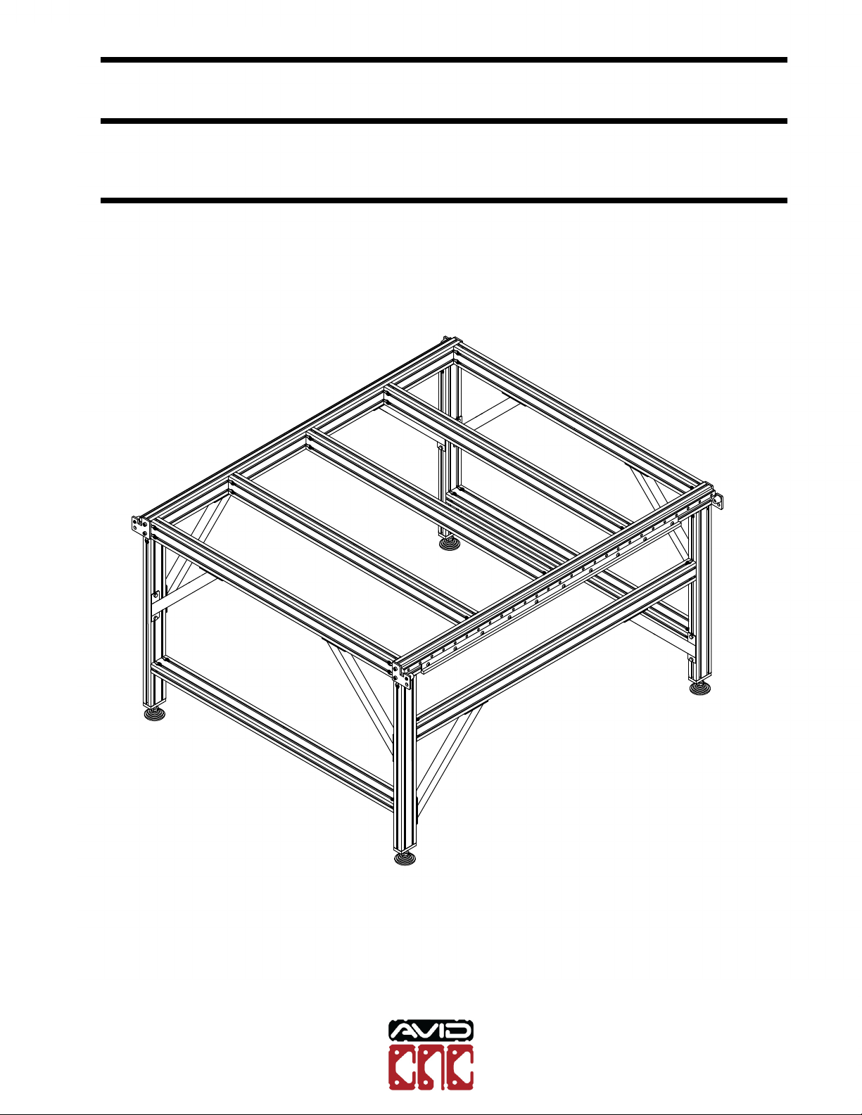
PRO4848 CNC 4' x 4'
Assembly Instructions
v2018Q4.3, 16.1 Model Revision

PRO Series 4848 Assembly CONTENTS
Contents
1 Base Assembly 3
1.1 Table Leg Assembly ................................ 4
1.2 Table Frame Assembly ............................... 25
1.3 Crossmember Installation ............................. 41
1.4 Linear Rail Installation ............................... 50
1.5 Gear Rack Installation ............................... 63
2 Riser Assembly 70
2.1 Linear Bearing Block Installation ......................... 71
2.2 Table Bumpers .................................... 78
2.3 Risers ......................................... 85
3 Gantry Assembly 99
3.1 Gantry Extrusion Installation ............................ 100
3.2 Gantry Gear Rack Installation .......................... 116
3.3 Linear Rail Installation ............................... 121
3.4 Gantry Bumper Installation ............................ 132
3.5 Gantry Carriage Installation ........................... 138
4 Rack and Pinion Drive Installation 147
4.1 NEMA 23 Drive Assembly ............................. 148
4.2 NEMA 34 Drive Assembly ............................. 163
4.3 R&P Drive Installation ................................ 178
5 Z-Axis Assembly 193
6 Cable Track Assembly 211
7 Motor and Sensor Connections 239
PRO Series 4848 Assembly
Version 2018Q4.1
Copyright©2018 CNC Router Parts LLC.
All Rights Reserved. 2
PRO4848 CNC
Assembly Instructions
16.1 Model Revision
Version 2018Q4.3
© 2020 Avid CNC
All Rights Reserved
PRO Series 4848 Assembly
1
Base Assembly
PRO Series 4848 Assembly
Version 2018Q4.1
Copyright©2018 CNC Router Parts LLC.
All Rights Reserved. 3
PRO4848 CNC
Assembly Instructions
16.1 Model Revision
Version 2018Q4.3
© 2020 Avid CNC
All Rights Reserved

PRO Series 4848 Assembly 1.1. TABLE LEG ASSEMBLY
1.1 Table Leg Assembly
Note: Skip this section if you did not purchase a Leg Kit.
Note: The Electronics Mounting Bar was added with the 2016Q4.1 revision of our
leg kit. If you purchased the previous revision, please contact us if you wish to up-
grade your leg kit. To assemble without the electronics mounting bar, please refer
to the Leg Kit revision 2016Q3.1 Assembly Diagram at http://www.cncrouterparts.com/leg-
kit-assembly-instructions-p-295.html
The following parts and bags will be used in this section:
•(4) 4080 Leg Extrusion, 750 mm
•(2) 4080 Leg Extrusion, 1250 mm
•(1) 4080 Leg Extrusion, 1440 mm
•(28) 40 Series Anchor Fastener
•(36) M8 x 30mm Socket Head Cap Screw
•(60) M8 Roll in T-Nut
•(4) 7111 Foot Plate
•(4) H172 Leveling Foot
•(8) CRP813-01 Leg Kit Gusset
•(32) M8 x 14mm Hex Cap Bolt
PRO Series 4848 Assembly
Version 2018Q4.1
Copyright©2018 CNC Router Parts LLC.
All Rights Reserved. 4
PRO4848 CNC
Assembly Instructions
16.1 Model Revision
Version 2018Q4.3
© 2020 Avid CNC
All Rights Reserved

PRO Series 4848 Assembly 1.1. TABLE LEG ASSEMBLY
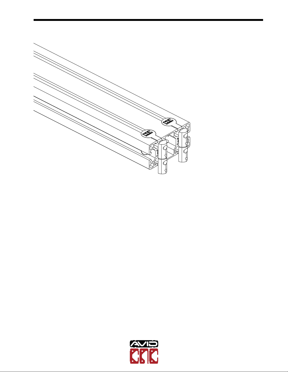
M8 x 30mm Socket Head Cap Screw
M8 Roll In T-Nut
4080 Leg Extrusion, 1250mm
•Thread the socket head cap screws into the t-nuts through the anchor fasteners
as indicated.
PRO Series 4848 Assembly
Version 2018Q4.1
Copyright©2018 CNC Router Parts LLC.
All Rights Reserved. 5
PRO4848 CNC
Assembly Instructions
16.1 Model Revision
Version 2018Q4.3
© 2020 Avid CNC
All Rights Reserved
PRO Series 4848 Assembly 1.1. TABLE LEG ASSEMBLY
•Slide the anchor assembly into the extrusion.
PRO Series 4848 Assembly
Version 2018Q4.1
Copyright©2018 CNC Router Parts LLC.
All Rights Reserved. 6
PRO4848 CNC
Assembly Instructions
16.1 Model Revision
Version 2018Q4.3
© 2020 Avid CNC
All Rights Reserved

PRO Series 4848 Assembly 1.1. TABLE LEG ASSEMBLY
•Repeat the previous steps on both sides for each of the 1250mm Leg extrusion
sections.
PRO Series 4848 Assembly
Version 2018Q4.1
Copyright©2018 CNC Router Parts LLC.
All Rights Reserved. 7
PRO4848 CNC
Assembly Instructions
16.1 Model Revision
Version 2018Q4.3
© 2020 Avid CNC
All Rights Reserved
PRO Series 4848 Assembly 1.1. TABLE LEG ASSEMBLY
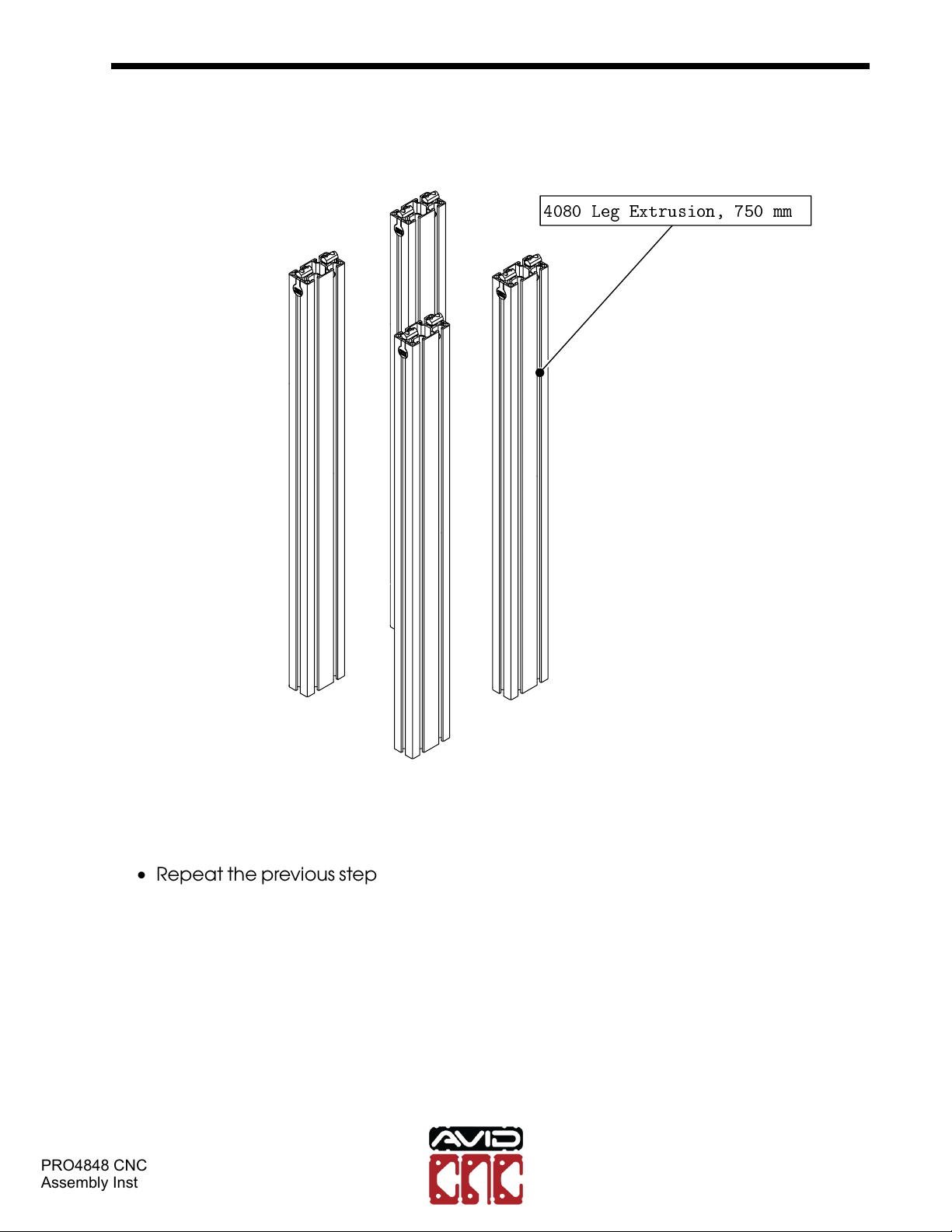
4080 Leg Extrusion, 750 mm
•Repeat the previous steps one side for each of the 750mm Leg extrusion sections.
PRO Series 4848 Assembly
Version 2018Q4.1
Copyright©2018 CNC Router Parts LLC.
All Rights Reserved. 8
PRO4848 CNC
Assembly Instructions
16.1 Model Revision
Version 2018Q4.3
© 2020 Avid CNC
All Rights Reserved
PRO Series 4848 Assembly 1.1. TABLE LEG ASSEMBLY
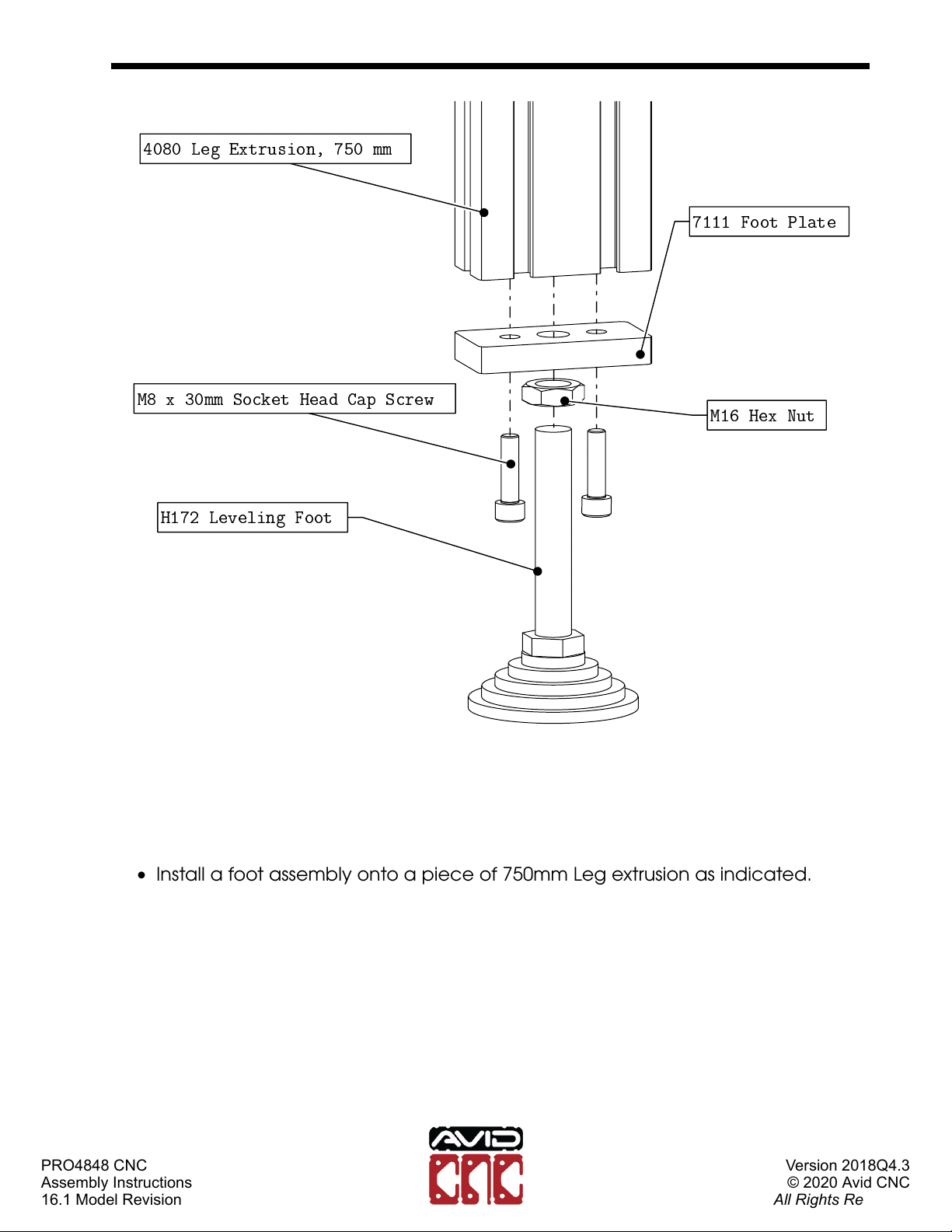
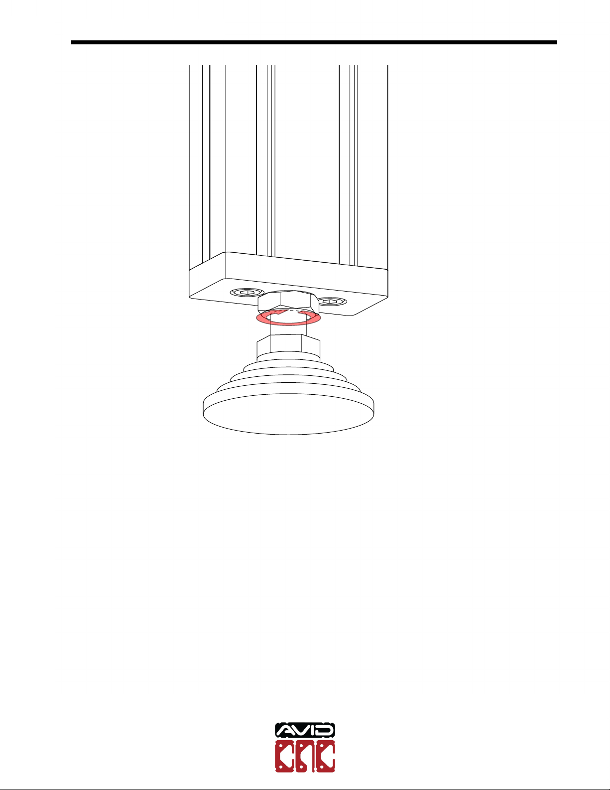
H172 Leveling Foot
M8 x 30mm Socket Head Cap Screw M16 Hex Nut
7111 Foot Plate
4080 Leg Extrusion, 750 mm
•Install a foot assembly onto a piece of 750mm Leg extrusion as indicated.
PRO Series 4848 Assembly
Version 2018Q4.1
Copyright©2018 CNC Router Parts LLC.
All Rights Reserved. 9
PRO4848 CNC
Assembly Instructions
16.1 Model Revision
Version 2018Q4.3
© 2020 Avid CNC
All Rights Reserved
PRO Series 4848 Assembly 1.1. TABLE LEG ASSEMBLY
•Fully tighten the highlighted fasteners.
PRO Series 4848 Assembly
Version 2018Q4.1
Copyright©2018 CNC Router Parts LLC.
All Rights Reserved. 10
PRO4848 CNC
Assembly Instructions
16.1 Model Revision
Version 2018Q4.3
© 2020 Avid CNC
All Rights Reserved

PRO Series 4848 Assembly 1.1. TABLE LEG ASSEMBLY
•Repeat the previous steps for each of the 750mm Leg extrusion as indicated.
PRO Series 4848 Assembly
Version 2018Q4.1
Copyright©2018 CNC Router Parts LLC.
All Rights Reserved. 11
PRO4848 CNC
Assembly Instructions
16.1 Model Revision
Version 2018Q4.3
© 2020 Avid CNC
All Rights Reserved
PRO Series 4848 Assembly 1.1. TABLE LEG ASSEMBLY
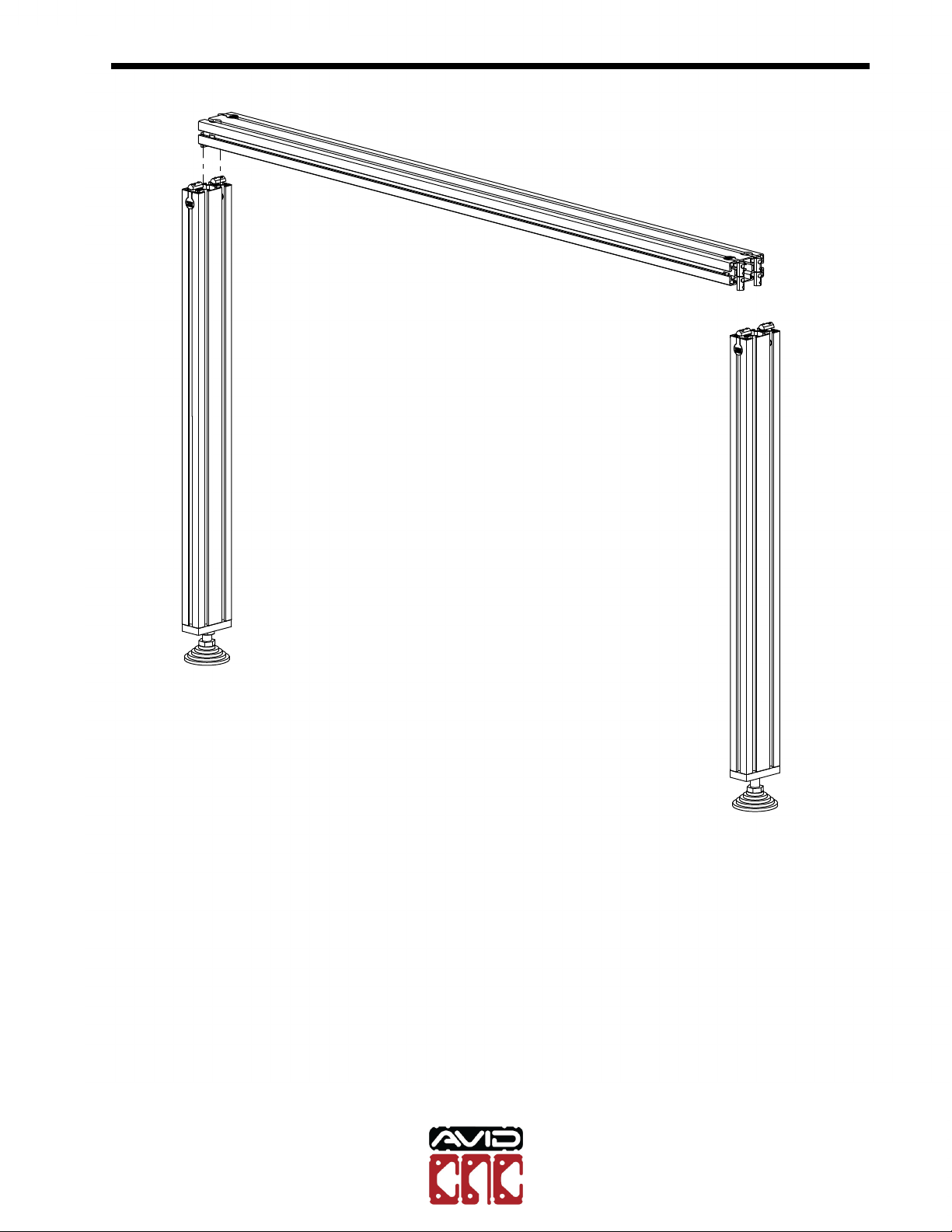
•Use a section of 1250mm Leg Extrusion to join two of the 750 mm Extrusion sec-
tions.
PRO Series 4848 Assembly
Version 2018Q4.1
Copyright©2018 CNC Router Parts LLC.
All Rights Reserved. 12
PRO4848 CNC
Assembly Instructions
16.1 Model Revision
Version 2018Q4.3
© 2020 Avid CNC
All Rights Reserved

PRO Series 4848 Assembly 1.1. TABLE LEG ASSEMBLY
6.5"
•Position the crossmember 6.5" (160mm) from the bottom of the leg.
PRO Series 4848 Assembly
Version 2018Q4.1
Copyright©2018 CNC Router Parts LLC.
All Rights Reserved. 13
PRO4848 CNC
Assembly Instructions
16.1 Model Revision
Version 2018Q4.3
© 2020 Avid CNC
All Rights Reserved
PRO Series 4848 Assembly 1.1. TABLE LEG ASSEMBLY
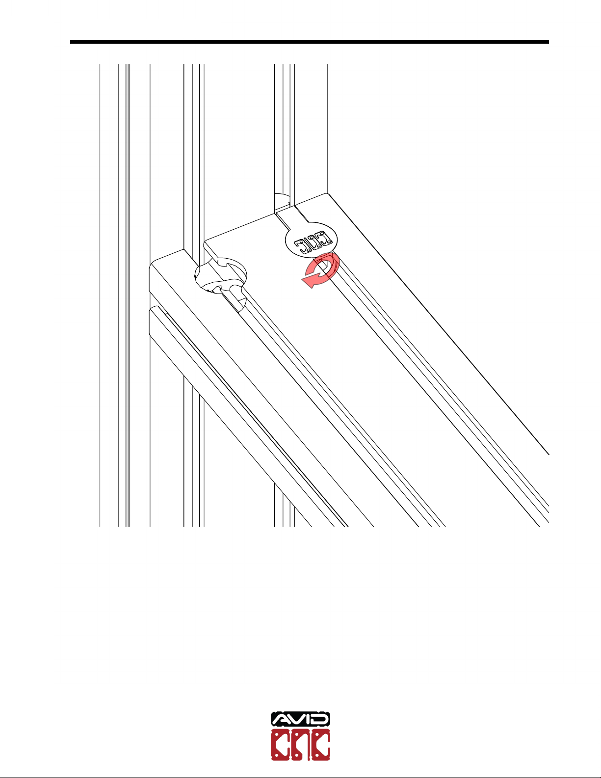
•Tighten all 8 of the anchor fasteners in the crossmember.
Note: For assembling anchor fastener connections, an M6 ball-end allen wrench
is required. An M6 ball-end driver attachment for a drill or impact driver can make
assembly more efficient.
PRO Series 4848 Assembly
Version 2018Q4.1
Copyright©2018 CNC Router Parts LLC.
All Rights Reserved. 14
PRO4848 CNC
Assembly Instructions
16.1 Model Revision
Version 2018Q4.3
© 2020 Avid CNC
All Rights Reserved

PRO Series 4848 Assembly 1.1. TABLE LEG ASSEMBLY
M8 x 14mm Hex Cap Bolt
M8 Roll In T-Nut
CRP813-01 Leg Kit Gusset
•Attach a leg gusset to a leg as indicated.
PRO Series 4848 Assembly
Version 2018Q4.1
Copyright©2018 CNC Router Parts LLC.
All Rights Reserved. 15
PRO4848 CNC
Assembly Instructions
16.1 Model Revision
Version 2018Q4.3
© 2020 Avid CNC
All Rights Reserved

PRO Series 4848 Assembly 1.1. TABLE LEG ASSEMBLY
!
•Partially tighten the highlighted fasteners.
Note: The top of the gusset should be roughly flush with the top of the extrusion.
PRO Series 4848 Assembly
Version 2018Q4.1
Copyright©2018 CNC Router Parts LLC.
All Rights Reserved. 16
PRO4848 CNC
Assembly Instructions
16.1 Model Revision
Version 2018Q4.3
© 2020 Avid CNC
All Rights Reserved
PRO Series 4848 Assembly 1.1. TABLE LEG ASSEMBLY
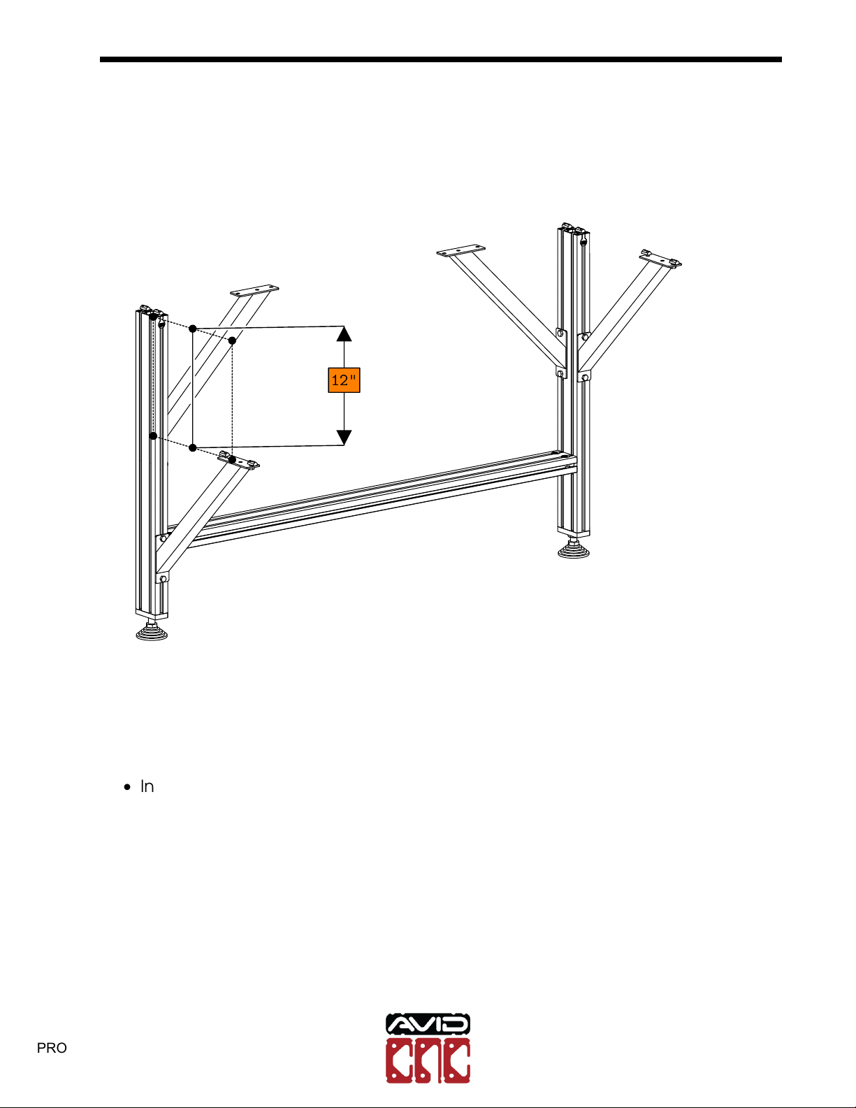
12"
•Install 3 additional gussets to the leg assembly as indicated.
Note: Do not prethread t-nuts into the inside gussets at this time.
Note: One gusset should be lowered by about 12" (300mm) to accomidate the
electronics mounting bar.
Note: Do not prethread t-nuts into the inside gussets at this time.
PRO Series 4848 Assembly
Version 2018Q4.1
Copyright©2018 CNC Router Parts LLC.
All Rights Reserved. 17
PRO4848 CNC
Assembly Instructions
16.1 Model Revision
Version 2018Q4.3
© 2020 Avid CNC
All Rights Reserved

PRO Series 4848 Assembly 1.1. TABLE LEG ASSEMBLY
•Repeat the previous steps with the remaining gussets and extrusion sections.
Note: Only two of the three leg sets should have a lowered gusset. The lowered
gussets should be on opposite legs as indicated.
PRO Series 4848 Assembly
Version 2018Q4.1
Copyright©2018 CNC Router Parts LLC.
All Rights Reserved. 18
PRO4848 CNC
Assembly Instructions
16.1 Model Revision
Version 2018Q4.3
© 2020 Avid CNC
All Rights Reserved
PRO Series 4848 Assembly 1.1. TABLE LEG ASSEMBLY
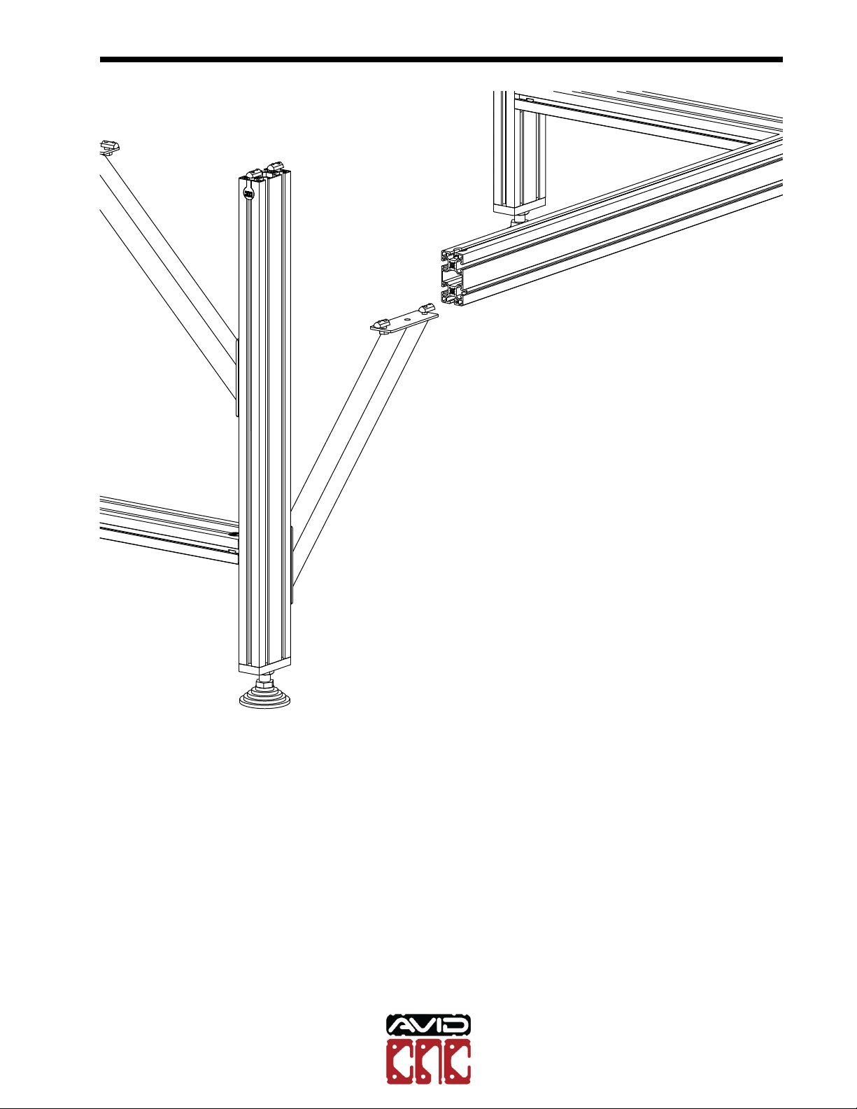
•Slide the 1440mm length of leg extrusion onto the lowered gussets as indicated.
PRO Series 4848 Assembly
Version 2018Q4.1
Copyright©2018 CNC Router Parts LLC.
All Rights Reserved. 19
PRO4848 CNC
Assembly Instructions
16.1 Model Revision
Version 2018Q4.3
© 2020 Avid CNC
All Rights Reserved

PRO Series 4848 Assembly 1.1. TABLE LEG ASSEMBLY
•Leave some space between the electronics mounting bar and the legs.
PRO Series 4848 Assembly
Version 2018Q4.1
Copyright©2018 CNC Router Parts LLC.
All Rights Reserved. 20
PRO4848 CNC
Assembly Instructions
16.1 Model Revision
Version 2018Q4.3
© 2020 Avid CNC
All Rights Reserved
Table of contents


