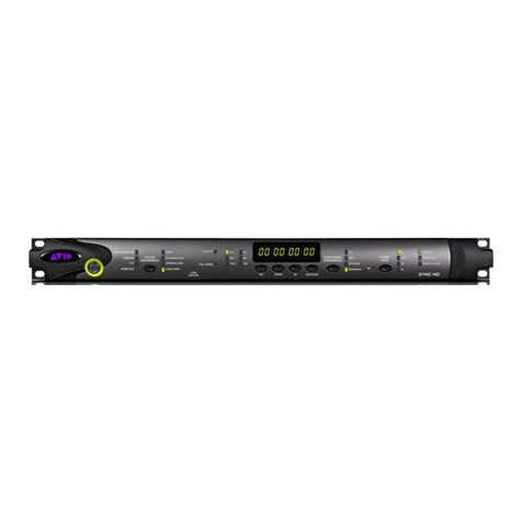
Avid Technology SYNC HD User manual

SYNC™HD Guide

Legal Notices
This guide is copyrighted ©2011 by Avid Technology, Inc.,
(hereafter “Avid”), with all rights reserved. Under copyright
laws, this guide may not be duplicated in whole or in part
without the written consent of Avid.
003, 96 I/O, 96i I/O, 192 Digital I/O, 192 I/O, 888|24 I/O,
882|20 I/O, 1622 I/O, 24-Bit ADAT Bridge I/O, AudioSuite,
Avid, Avid DNA, Avid Mojo, Avid Unity, Avid Unity ISIS,
Avid Xpress, AVoption, Axiom, Beat Detective,
Bomb Factory, Bruno, C|24, Command|8, Control|24, D-
Command, D-Control, D-Fi, D-fx, D-Show, D-Verb, DAE,
Digi 002, DigiBase, DigiDelivery, Digidesign,
Digidesign Audio Engine, Digidesign Intelligent Noise
Reduction, Digidesign TDM Bus, DigiDrive, DigiRack,
DigiTest, DigiTranslator, DINR, DV Toolkit, EditPack, Eleven,
HD Core, HD Process, Hybrid, Impact, Interplay, LoFi,
M-Audio, MachineControl, Maxim, Mbox, MediaComposer,
MIDI I/O, MIX, MultiShell, Nitris, OMF, OMF Interchange,
PRE, ProControl, Pro Tools M-Powered, Pro Tools,
Pro Tools|HD, Pro Tools LE, QuickPunch, Recti-Fi,
Reel Tape, Reso, Reverb One, ReVibe, RTAS, Sibelius,
Smack!,SoundReplacer,SoundDesigner II,Strike,Structure,
SYNC HD, SYNC I/O, Synchronic, TL Aggro, TL AutoPan,
TL Drum Rehab, TL Everyphase, TL Fauxlder, TL In Tune,
TL MasterMeter,TL Metro,TL Space,TL Utilities, Transfuser,
Trillium Lane Labs, Vari-Fi Velvet, X-Form, and XMON are
trademarks or registered trademarks of Avid Technology, Inc.
Xpand!isRegisteredin theU.S.PatentandTrademarkOffice.
All other trademarks are the property of their respective
owners.
Product features, specifications, system requirements, and
availability are subject to change without notice.
Guide Part Number 9329-65169-00 REV A 10/11
Documentation Feedback
At Avid, we are always looking for ways to improve our
documentation. If you have comments, corrections, or
suggestions regarding our documentation, email us at

Contents iii
Chapter 1. Introduction . . . . . . . . . . . . . . . . . . . . . . . . . . . . . . . . . . . . . . . . . . . . . . . . . . . . . . . . . 1
SYNC Peripheral Features. . . . . . . . . . . . . . . . . . . . . . . . . . . . . . . . . . . . . . . . . . . . . . . . . . 2
System Requirements and Compatibility. . . . . . . . . . . . . . . . . . . . . . . . . . . . . . . . . . . . . . . . 3
Registration. . . . . . . . . . . . . . . . . . . . . . . . . . . . . . . . . . . . . . . . . . . . . . . . . . . . . . . . . . . . . 4
About This Guide. . . . . . . . . . . . . . . . . . . . . . . . . . . . . . . . . . . . . . . . . . . . . . . . . . . . . . . . . 4
Conventions Used in This Guide. . . . . . . . . . . . . . . . . . . . . . . . . . . . . . . . . . . . . . . . . . . . . . 4
About www.avid.com . . . . . . . . . . . . . . . . . . . . . . . . . . . . . . . . . . . . . . . . . . . . . . . . . . . . . . 5
Chapter 2. Installation and Configuration . . . . . . . . . . . . . . . . . . . . . . . . . . . . . . . . . . . . . . . . . . 7
Hardware Connections. . . . . . . . . . . . . . . . . . . . . . . . . . . . . . . . . . . . . . . . . . . . . . . . . . . . . 7
MachineControl . . . . . . . . . . . . . . . . . . . . . . . . . . . . . . . . . . . . . . . . . . . . . . . . . . . . . . . . . . 9
Synchronization and Timecode Connections to Machines, Decks, and Other Devices. . . . . . . 9
Software Installation. . . . . . . . . . . . . . . . . . . . . . . . . . . . . . . . . . . . . . . . . . . . . . . . . . . . . . 12
Emulating a SYNC I/O . . . . . . . . . . . . . . . . . . . . . . . . . . . . . . . . . . . . . . . . . . . . . . . . . . . . 13
Configuring a SYNC Peripheral from Pro Tools . . . . . . . . . . . . . . . . . . . . . . . . . . . . . . . . . . 14
MachineControl Configuration . . . . . . . . . . . . . . . . . . . . . . . . . . . . . . . . . . . . . . . . . . . . . . 20
Software Configuration for the SYNC Setup Software Utility. . . . . . . . . . . . . . . . . . . . . . . . . 20
Troubleshooting. . . . . . . . . . . . . . . . . . . . . . . . . . . . . . . . . . . . . . . . . . . . . . . . . . . . . . . . . 21
Chapter 3. SYNC Peripheral Hardware and Software. . . . . . . . . . . . . . . . . . . . . . . . . . . . . . . . 23
SYNC Peripheral Front Panel. . . . . . . . . . . . . . . . . . . . . . . . . . . . . . . . . . . . . . . . . . . . . . . 23
SYNC Peripheral Back Panel . . . . . . . . . . . . . . . . . . . . . . . . . . . . . . . . . . . . . . . . . . . . . . . 26
SYNC Setup Software Utility. . . . . . . . . . . . . . . . . . . . . . . . . . . . . . . . . . . . . . . . . . . . . . . . 28
Chapter 4. Using SYNC Peripherals. . . . . . . . . . . . . . . . . . . . . . . . . . . . . . . . . . . . . . . . . . . . . . 33
SYNC Peripheral Controls in Pro Tools, SYNC Setup Software Utility, and the Front Panel . . 34
Front Panel Generator/Parameter Switches . . . . . . . . . . . . . . . . . . . . . . . . . . . . . . . . . . . . 35
Clock References and Options . . . . . . . . . . . . . . . . . . . . . . . . . . . . . . . . . . . . . . . . . . . . . . 36
Positional Reference and Options. . . . . . . . . . . . . . . . . . . . . . . . . . . . . . . . . . . . . . . . . . . . 43
Compensating for Timecode Offsets. . . . . . . . . . . . . . . . . . . . . . . . . . . . . . . . . . . . . . . . . . 49
Generating & Regenerating Timecode . . . . . . . . . . . . . . . . . . . . . . . . . . . . . . . . . . . . . . . . 49
Contents

SYNC HD Guideiv
Generating a Window Dub. . . . . . . . . . . . . . . . . . . . . . . . . . . . . . . . . . . . . . . . . . . . . . . . . 56
Sync Status Indicators in the Edit Window . . . . . . . . . . . . . . . . . . . . . . . . . . . . . . . . . . . . . 58
Chapter 5. Additional Operational Information. . . . . . . . . . . . . . . . . . . . . . . . . . . . . . . . . . . . . 59
Front Panel Generator/Parameter Controls. . . . . . . . . . . . . . . . . . . . . . . . . . . . . . . . . . . . . 59
Using Fader Start . . . . . . . . . . . . . . . . . . . . . . . . . . . . . . . . . . . . . . . . . . . . . . . . . . . . . . . 66
Calibrating the SYNC Peripheral Oscillator. . . . . . . . . . . . . . . . . . . . . . . . . . . . . . . . . . . . . 66
Restoring Factory Settings. . . . . . . . . . . . . . . . . . . . . . . . . . . . . . . . . . . . . . . . . . . . . . . . . 68
Managing and Selecting Video Inputs . . . . . . . . . . . . . . . . . . . . . . . . . . . . . . . . . . . . . . . . 69
Appendix A. Additional Synchronization Information. . . . . . . . . . . . . . . . . . . . . . . . . . . . . . . 71
Video and VITC Signals . . . . . . . . . . . . . . . . . . . . . . . . . . . . . . . . . . . . . . . . . . . . . . . . . . 71
LTC Signals . . . . . . . . . . . . . . . . . . . . . . . . . . . . . . . . . . . . . . . . . . . . . . . . . . . . . . . . . . . 72
Auto-Switch LTC/VITC . . . . . . . . . . . . . . . . . . . . . . . . . . . . . . . . . . . . . . . . . . . . . . . . . . . 72
Digital Clock Signal Types. . . . . . . . . . . . . . . . . . . . . . . . . . . . . . . . . . . . . . . . . . . . . . . . . 73
Bi-Phase/Tach . . . . . . . . . . . . . . . . . . . . . . . . . . . . . . . . . . . . . . . . . . . . . . . . . . . . . . . . . 74
Pilot Tone. . . . . . . . . . . . . . . . . . . . . . . . . . . . . . . . . . . . . . . . . . . . . . . . . . . . . . . . . . . . . 75
Appendix B. Technical Specifications. . . . . . . . . . . . . . . . . . . . . . . . . . . . . . . . . . . . . . . . . . . . 77
Appendix C. Wiring Diagrams and Pin Assignments . . . . . . . . . . . . . . . . . . . . . . . . . . . . . . . 85
LTC Connectors . . . . . . . . . . . . . . . . . . . . . . . . . . . . . . . . . . . . . . . . . . . . . . . . . . . . . . . . 85
Bi-Phase/GPI/Pilot Pin Diagram. . . . . . . . . . . . . . . . . . . . . . . . . . . . . . . . . . . . . . . . . . . . . 86
Bi-phase/Tach OptoCoupler Input . . . . . . . . . . . . . . . . . . . . . . . . . . . . . . . . . . . . . . . . . . . 87
GPI Relay Outputs . . . . . . . . . . . . . . . . . . . . . . . . . . . . . . . . . . . . . . . . . . . . . . . . . . . . . . 88
GPI (TTL)/MTC Outputs . . . . . . . . . . . . . . . . . . . . . . . . . . . . . . . . . . . . . . . . . . . . . . . . . . 89
GPI (opto) Inputs. . . . . . . . . . . . . . . . . . . . . . . . . . . . . . . . . . . . . . . . . . . . . . . . . . . . . . . . 90
Connector Pin Assignments. . . . . . . . . . . . . . . . . . . . . . . . . . . . . . . . . . . . . . . . . . . . . . . . 91
SYNC Peripheral Cable Pin Assignments. . . . . . . . . . . . . . . . . . . . . . . . . . . . . . . . . . . . . . 93
Bi-phase/Tach/GPI/Pilot Port Interfacing Notes. . . . . . . . . . . . . . . . . . . . . . . . . . . . . . . . . . 94
Appendix D. Compliance Information . . . . . . . . . . . . . . . . . . . . . . . . . . . . . . . . . . . . . . . . . . . . 95
Environmental Compliance . . . . . . . . . . . . . . . . . . . . . . . . . . . . . . . . . . . . . . . . . . . . . . . . 95
EMC (Electromagnetic Compliance). . . . . . . . . . . . . . . . . . . . . . . . . . . . . . . . . . . . . . . . . . 96
Safety Compliance . . . . . . . . . . . . . . . . . . . . . . . . . . . . . . . . . . . . . . . . . . . . . . . . . . . . . . 97
Index . . . . . . . . . . . . . . . . . . . . . . . . . . . . . . . . . . . . . . . . . . . . . . . . . . . . . . . . . . . . . . . . . . . . . . 99

Chapter 1: Introduction 1
Chapter 1: Introduction
This guide covers operation of Avid®multipur-
pose SYNC peripherals (SYNC HD®and
SYNC I/O®) for Avid Pro Tools|HD®and
HD Native®systems.
SYNC peripherals support all Pro Tools®sample
rates, and synchronize to most major timecode
and clock reference standards used in audio,
video, film, and multimedia production.
SYNC peripherals can also be used as standalone
synchronization devices.
SYNC Peripherals with Pro Tools
Systems
(Avid Pro Tools|HD or HD Native Hardware
Required)
With a Pro Tools system with Avid
Pro Tools|HD or HD Native hardware, SYNC pe-
ripherals provide highly accurate lock to time-
code. Most SYNC peripheral settings are avail-
able directly from within Pro Tools.
SYNC Peripherals in Standalone Mode
SYNC peripherals can be used as standalone
synchronization converters, timecode genera-
tors, clock generators and timecode character
generators. Throughout this guide, the term
standalone refers to systems using a SYNC pe-
ripheral, but not using Pro Tools to communi-
cate to the SYNC peripheral.
When used as a standalone device (or in “Stand-
alone mode”), a SYNC peripheral is connected to
timecode or clock signals, and is configured
from the front panel. Optionally, while in Stand-
alone mode, a SYNC peripheral can be con-
trolled remotely from a Windows computer us-
ing the SYNC Setup software utility.
SYNC Setup Software Utility
(Windows Only)
In standalone mode, a SYNC peripheral con-
nected to a supported Windows computer can be
controlled using the SYNC Setup software util-
ity.

SYNC HD Guide2
SYNC Peripheral Features
SYNC peripherals support all Pro Tools sample
rates (44.1, 48, 88.2, 96, 176.4, and 192 kHz).
The SYNC HD supports both industry standard
SD (standard definition) and HD (high-defini-
tion) video reference rates. The SYNC I/O sup-
ports SD video reference rates only.
SYNC peripherals provide the following features
with Pro Tools:
Supported Positional Reference Sources
•LTC
•VITC
• Serial Timecode
•Bi-phase/Tach
Supported Clock Reference Sources
•LoopSync
•VideoReference
• SD reference rates
• HD reference rates (SYNC HD only)
•CompositeVideoInput
•WordClock
• AES/EBU (DARS per AES-11 standard)
•PilotTone
•InternalCrystal
•Bi-phase/Tach
•LTC
Output and Generation
•LoopSync
• Avid Super Clock (256x sample clock)
•WordClock(1xsampleclock)
•AES/EBUnullclock(AES“digitalblack”)
• VITC (if a video input is present)
•LTC
• MIDI Timecode (MTC)
• Dual 9-pin Sony P-2 protocol ports (only one
can be active at a time), for limited serial deck
control with MachineControl software option
for Pro Tools.
Other Features
• Front panel controls and a large LED display
of timecode and parameters
• Integrated control from Pro Tools
• Timecode Character Generator
• Fader start, provided through GPI output, for
remote transport control from select Pro Tools
fader movement
• Standalone remote control through SYNC
Setup software utility (Windows only)
• Field-updatable firmware
•SYNCI/OEmulationforlegacysoftwaresup-
port (SYNC HD only)

Chapter 1: Introduction 3
Controlling SYNC Peripherals in
Standalone Mode
If you are using a SYNC peripheral in Stand-
alone mode, you can control it with the SYNC
Setup software utility (Windows only), or with
the switches on the front panel of the SYNC pe-
ripheral.
The SYNC Setup software utility (Windows
only) gives you access to all SYNC peripheral
controls. The front panel provides the same con-
trols, except for the following:
• Variable Speed Override (VSO)
• Window dub parameters: While you can
turn the Window dub on or off from the
front panel, you cannot configure its dis-
play parameters without Pro Tools or the
SYNC Setup software utility.
System Requirements and
Compatibility
SYNC Peripherals with Pro Tools
To use a SYNC peripheral with Pro Tools, the
following is required:
• A qualified Pro Tools system with Avid
Pro Tools|HD or HD Native hardware
• An available DigiSerial port on the system’s
core card (HD Accel Core, HD Core, or
HD Native)
• An 8-pin to 8-pin serial cable (included) to
connect the SYNC peripheral to the DigiSerial
port on a Pro Tools core card
SYNC Setup Software Utility
(Windows Only)
The optional SYNC Setup software utility re-
quires the following:
• A qualified Windows computer.
• An available COM port or serial port on the
computer to connect to the SYNC peripheral.
(You cannot run the SYNC Setup software util-
ity through the DigiSerial port on Pro Tools
cards.)
• A non-standard 9-pin to 8-pin cable is re-
quired to connect the SYNC peripheral to a
COM port or serial port on a Windows com-
puter. Wiring instructions for making the re-
quired cable are in Appendix C, “Wiring
Diagrams and Pin Assignments.”
Compatibility Information
Avid can only assure compatibility and provide
support for hardware and software it has tested
and approved.
For complete system requirements and a list of
qualified computers, operating systems, hard
drives, and third-party devices, visit:
www.avid.com/compatibility
See “SYNC Peripheral Controls in
Pro Tools, SYNC Setup Software Utility,
and the Front Panel” on page 34.
If you use a custom serial cable between
Pro Tools and the SYNC peripheral, be sure
the cable supports hardware handshaking.
The maximum supported length for this ca-
ble is 100 ft.
For more information, see “Wiring Dia-
grams and Pin Assignments” on page 85.
The computer requirements for the SYNC
Setup software utility are different from the
computer requirements for Pro Tools. You
can run the SYNC Setup software utility
from slower Windows computers.

SYNC HD Guide4
Registration
Review the enclosed Registration Information
Card and follow the instructions on it to quickly
register your purchase online. By registering,
you become eligible to receive the following:
• Technical support information
• Software update and upgrade notices
• Hardware warranty information
About This Guide
This guide assumes:
• You understand the basics of synchroniza-
tion and timecode
• You know how to operate devices that send
or receive timecode, such as a video deck
• You have an understanding of the timecode
requirements for your projects
This Guide covers use of the SYNC HD and the
SYNC I/O with Pro Tools version 10.0 and
higher.
For versions of Pro Tools lower than 7.3,
the SYNC HD can be set to emulate a
SYNC I/O. See our website (www.avid.com)
for a version of the SYNC I/O Guide that
applies to your system.

Chapter 1: Introduction 5
Conventions Used in This
Guide
All of our guides use the following conventions
to indicate menu choices and key commands:
:
The names of Commands, Options, and Settings
that appear on-screen are in a different font.
The following symbols are used to highlight
important information:
About www.avid.com
The Avid website (www.avid.com) is your best
online source for information to help you get the
most out of your Pro Tools system. The follow-
ing are just a few of the services and features
available.
Product Registration
Register your purchase
online.
Support and Downloads
Contact Avid Customer
Success (technical support); download software
updates and the latest online manuals; browse
the Compatibility documents for system re-
quirements; search the online Knowledge Base
or join the worldwide Pro Tools community on
the User Conference.
Training and Education
Study on your own using
courses available online or find out how you can
learn in a classroom setting at a certified
Pro Tools training center.
Products and Developers
Learn about Avid
products; download demo software or learn
about our Development Partners and their plug-
ins, applications, and hardware.
News and Events
Get the latest news from Avid
or sign up for a Pro Tools demo.
Convention Action
File > Save Choose Save from the
File menu
Control+N Hold down the Control key
and press the N key
Control-click Hold down the Control key
and click the mouse button
Right-click Click with the right
mouse button
User Tips are helpful hints for getting the
most from your system.
Important Notices include information that
could affect your data or the performance of
your system.
Shortcuts show you useful keyboard or
mouse shortcuts.
Cross References point to related sections in
this guide and other Pro Tools guides.

SYNC HD Guide6

Chapter 2: Installation and Configuration 7
Chapter 2: Installation and Configuration
Hardware Connections
The following are the primary hardware connec-
tions on a SYNC peripheral:
•ACPower
• Serial to a DigiSerial port on a Pro Tools core
card (HD Accel Core, HD Core, or HD Native),
or a serial port on a Windows computer
• Clock to Pro Tools audio interfaces
• 9-pin to external machines (requires the
Pro Tools MachineControl Software option)
• Synchronization, including positional and
clock references to and from remote machines
AC Power
SYNC peripheral AC connectors accept a stan-
dard AC power cable. SYNC peripherals are auto
power-selecting (100V to 240V) and will auto-
matically work with a standard modular cable to
connect to AC power receptacles in any country.
Serial Connections
Serial to Pro Tools Core Card
Pro Tools systems require a serial connection
between the SYNC peripheral and a Pro Tools
core card.
To connect a SYNC peripheral to a Pro Tools core
card:
1 Make sure power is off on all equipment.
2 Connect one end of the included serial cable to
the SYNC peripheral Host Serial port.
3 Connect the other end to the DigiSerial port
on your Pro Tools core card.
Do not use the DigiSerial port on any other
Pro Tools card in your system.

SYNC HD Guide8
Serial Connections in Standalone Mode
for the SYNC Setup Software Utility
(Windows Only)
To use the optional SYNC Setup software utility
to communicate with a standalone SYNC pe-
ripheral, you need a serial connection from the
SYNC peripheral to a supported Windows com-
puter. (For compatibility information, see “Sys-
tem Requirements and Compatibility” on
page 3.)
To connect a SYNC peripheral to a Windows
computer for the SYNC Setup software utility:
1 Purchase or make the required 9-pin to 8-pin
cable. For wiring details, see “SYNC Setup Soft-
ware Utility Cable” on page 93.
2 Make sure power is off on all equipment.
3 Connect the SYNC peripheral Host Serial port
to an available serial or COM port on your com-
puter.
4 Restore power to the SYNC peripheral, and re-
start your computer.
Clock for Pro Tools
Audio Interfaces
The SYNC peripheral must be connected to all
HD interfaces in the Loop Sync chain.
Connecting Loop Sync for Pro Tools HD
Audio Interfaces
SYNC peripherals support Loop Sync, and can
serve as Loop Sync Master. Loop Sync is a dedi-
cated clock loop for synchronizing multiple
Pro Tools HD interfaces (including the SYNC
peripheral).
To connect a SYNC peripheral to Pro Tools HD
interfaces:
1 Using a BNC cable, connect the Loop Sync Out
of the SYNC peripheral to the Loop Sync In of
your primary HD audio interface.
2 Using a second BNC cable, connect the SYNC
peripheral Loop Sync In to the Loop Sync Out of
your HD interface.
When using more than one HD audio interface,
make the SYNC peripheral the first and last unit
in the Loop Sync chain.
The SYNC Setup software utility will not
control the SYNC peripheral through the
DigiSerial port.
Loop Sync connections for SYNC peripheral and
96 I/O
Loop Sync in an expanded Pro Tools system
MTC OUT
HOST SERIAL
AC 100-240V, 50-60HZ, .5A 30W
VIDEO REF 9-PIN OUT 2
9-PIN OUT 1
WORD CLOCK (1x,256x)
VIDEO
L
T
C
I
N
A
E
S
I
N
A
E
S
O
U
T
L
T
C
O
U
T
IN
OUT
IN
OUT
IN
OUT
LOOP SYNC
INTERNALLY
TERMINATED
BI-PHASE / TACH / GPI / PILOT
SERIAL NUMBER
964530300294856
Loop Sync
SYNC peripheral
96 I/O Interface
MTC OUT
HOST SERIAL
AC 100-240V, 50-60HZ, .5A 30W
VIDEO REF 9-PIN OUT 2
9-PIN OUT 1
WORD CLOCK (1x,256x)
VIDEO
L
T
C
I
N
A
E
S
I
N
A
E
S
O
U
T
L
T
C
O
U
T
IN
OUT
IN
OUT
IN
OUT
LOOP SYNC
INTERNALLY
TERMINATED
BI-PHASE / TACH / GPI / PILOT
SERIAL NUMBER
964530300294856
SYNC peripheral
HD Interfaces

Chapter 2: Installation and Configuration 9
MachineControl
On MachineControl-enabled Pro Tools systems,
SYNC peripherals support limited Serial Deck
Control only. For full use of MachineControl op-
tion features, a direct serial connection to the
host Pro Tools computer is required.
Serial Deck Control Mode
(Non-Linear Decks Only)
A limited degree of Serial Deck Control mode is
available through a connection to the 9-pin
ports on the SYNC peripheral. For full Serial
Deck Control, a direct serial connection to the
host Pro Tools computer is required.
To connect an external deck to a SYNC peripheral:
Connect a standard 9-pin cable from one of
the 9-pin Out ports on the SYNC peripheral to
the 9-pin connector of the external deck.
As many as two decks can be connected to the
two 9-pin Out ports on the SYNC peripheral.
You can control one deck at a time, switching
between them from within Pro Tools. These
ports on the SYNC peripheral support all Ma-
chineControl modes except 9-Pin Remote (Deck
Emulation) mode.
9-Pin Remote Deck Emulation
Mode
9-Pin Remote Deck Emulation mode requires a
direct serial connection to the host computer.
Synchronization and
Timecode Connections to
Machines, Decks, and Other
Devices
The following sections describe connections re-
quired for different applications. For more in-
formation on timecode applications, see
Appendix A, “Additional Synchronization In-
formation.”
Connecting a Video Source
This section describes connections required
when using house video reference (SD or HD).
To have the SYNC peripheral resolve to house
sync:
Connect the house video reference, black
burst, or tri-level sync source to a Video Ref port
on the SYNC peripheral.
To have the SYNC peripheral resolve directly to an
incoming SD video signal:
Connect the SD video signal to the SYNC pe-
ripheral Video In port.
Due to performance limitations, this
configuration should be used primarily
with non-linear decks.
For more information on MachineControl
connections and operation, see the
MachineControl Guide.
The Video Ref ports are a non-terminated
loop-through connection. If the second
Video Ref port is not used, then you must
terminate it using the included 75-ohm
BNC terminator.

SYNC HD Guide10
Character Generator for Timecode
Window Dub
SYNC peripherals can generate a timecode win-
dow dub on SD signals coming into the Video In
port.
To use the SYNC peripheral Timecode Character
Generator to make a window burn:
1 Connect an SD video signal to the SYNC pe-
ripheral Video In port.
2 Connect the SYNC peripheral Video Out port
to other video devices, ensuring that the signal
is terminated by the last device in the chain.
Connecting LTC
SYNC peripherals provide LTC input and output
connectors.
To input LTC to a SYNC peripheral:
Connect the LTC signal from your machine,
synchronizer or other source to the SYNC pe-
ripheral LTC In port.
To output LTC from a SYNC peripheral:
Connect the SYNC peripheral LTC Out port to
your external devices.
Connecting Word Clock Devices
SYNC peripherals have Word Clock input and
output ports, which can be used simultaneously.
Use Word Clock when you want the SYNC pe-
ripheral to lock to 1x clock from DAT machines,
DA-88s, and similar digital devices.
Pro Tools HD audio interfaces each have their
own Word Clock inputs, which provide addi-
tional clock options and flexibility. Refer to
Pro Tools documentation for details.
To input Word Clock to a SYNC peripheral:
Connect Word Clock from the master Word
clock signal or device to the SYNC peripheral
Word Clock In.
To supply Word Clock from a SYNC peripheral:
Connect the SYNC peripheral Word Clock Out
to the Word Clock input of a digital device.
Make sure the SYNC peripheral Word Clock Out
port is configured to 1x for Word Clock.
Word Clock contains no positional information.
If you want devices to play or record in sync,
you’ll still need to provide them with a
positional reference.
For SYNC HD only, even when you have an
HD video reference signal connected to the
Video Ref connector, you can still connect an
SD video signal to the Video In connector to
provide a window dub.
SYNC peripherals can generate timecode to
provide positional reference to other de-
vices. See “Generating & Regenerating
Timecode” on page 49.

Chapter 2: Installation and Configuration 11
Connecting AES/EBU Devices
To input AES/EBU clock reference to a SYNC
peripheral:
Connect the device’s AES/EBU output to the
SYNC peripheral AES/EBU input.
To supply AES/EBU clock reference from a SYNC
peripheral:
Connect the SYNC peripheral AES/EBU output
to the AES/EBU reference input on a DAT ma-
chine or other digital device. (AES/EBU clock
does not support 176.4 kHz or 192 kHz sample
rates.)
Connecting MIDI Timecode
Devices
The SYNC peripheral MTC Out port supplies
MIDI timecode, derived from conversion (from
LTC, VITC or Bi-Phase) or from MTC genera-
tion, to synchronize MTC-compatible consoles,
sequencers, lighting systems, and other devices.
MIDI timecode from the MTC Out port always
matches the timecode address displayed on the
SYNC peripheral front panel. To supply MTC
from the SYNC peripheral to another MTC-com-
patible device, connect the device as described
below.
To connect an MTC-compatible device to receive
MTC from a SYNC peripheral:
Connect the SYNC peripheral MTC Out port to
the appropriate MIDI input on the device, using
a standard MIDI cable.
Pro Tools and MTC
Pro Tools receives MTC from SYNC peripherals
through its connection to the SYNC peripheral
Host Serial port. This signal does not include
standard MIDI timecode, but is instead a high-
quality, proprietary timecode signal designed
for Pro Tools. A MIDI Interface is not required
for Pro Tools to receive MTC.
MTC is output whenever the SYNC peripheral is
generating timecode. This MTC output can be
muted when timecode (LTC) is idle. See “MTC
Output and Idle Muting” on page 56 for details.

SYNC HD Guide12
Software Installation
The following sections provide instructions to
install software required to use a SYNC periph-
eral with Pro Tools or with the standalone
SYNC Setup software (Windows only).
SYNC Peripherals with
Pro Tools
All software required to use SYNC peripherals is
installed with Pro Tools software.
Updating SYNC Peripheral
Firmware
SYNC peripheral firmware is updated from the
DigiTest application.
To update SYNC Peripheral firmware:
1 Confirm that the SYNC peripheral is properly
connected to your computer in one of the follow-
ing ways:
• If it is connected to a Pro Tools system, it
should be connected to a DigiSerial Port on
an HD Accel Core, HD Core, or HD Native
card.
• If it is connected to a Windows computer
without Pro Tools, it should be connected
to the COM 1 port on the computer with a
standard serial cable.
2 Ensure that Pro Tools is not running.
3 Launch the Avid DigiTest application.
4 Click SYNC Firmware.
5 If you are using a DigiSerial Port connection,
make sure you have selected the HD Accel Core,
HD Core, or HD Native card from the pop-up
menu.
6 Select the type of port connection for the
SYNC peripheral (DigiSerial Port or COM Port).
7 Select the Synchronizer Type that you are up-
dating (SYNC HD or SYNC I/O).
8 Click Begin Update.
9 Locate the firmware file you want to use, and
click Open.
10 Follow the on-screen instructions to power
cycle the SYNC peripheral while holding the Set
button.
11 Wait for the firmware update to complete. Do
not power off the SYNC peripheral while the up-
date is in progress.
12 When the update is complete, follow any on-
screen instructions.
13 Click Quit to quit the DigiTest application.
The availability of SYNC peripheral features
depends on the version of Pro Tools software
you are running. For details on features
available with your version of Pro Tools,
visit www.avid.com.

Chapter 2: Installation and Configuration 13
SYNC Peripherals with SYNC
Setup Software Utility
(Windows Only)
When using a SYNC peripheral in Standalone
mode, it can be controlled remotely using the
SYNC Setup software utility. Updates to this
utility can be downloaded from www.avid.com.
To install the SYNC Setup software utility on
Windows:
1 Make sure the SYNC peripheral is connected to
a serial or COM port on your computer. See “Se-
rial Connections in Standalone Mode for the
SYNC Setup Software Utility” on page 8.
2 Insert the installer disc containing the latest
SYNC Setup software, or navigate to its location
if you downloaded an update.
3 Launch the installer and follow the on-screen
instructions.
Emulating a SYNC I/O
(SYNC HD Only)
If you are using a SYNC HD with Pro Tools 7.4
or higher, Pro Tools will automatically recognize
the SYNC HD.
If you are using a SYNC HD with Pro Tools
version 7.3 or lower, set the SYNC HD to emulate
a SYNC I/O.
To set a SYNC HD to emulate a SYNC I/O:
1 Press Set, and use the Up and Down switches to
display “Device ID” (dEuicE id).
2 Press Set. The LED Timecode Display shows
the current Device ID for the unit: “SYNC HD”
(SYncHD)or“SYNCI/O”(SYncIO).
3 Press the Up or Down switches to toggle the
Device ID to read “SYNC I/O” (SYnc IO).
4 Press Set.

SYNC HD Guide14
Configuring a SYNC
Peripheral from Pro Tools
Pro Tools HD software provides configuration
controls that establish communication between
Pro Tools and the SYNC peripheral.
Loop Sync
SYNC peripherals support the Loop Sync feature
for connecting Pro Tools HD interfaces. A SYNC
peripheral can be configured as the Clock Source
(Loop Master) in order to provide Loop Sync
master clock to the rest of your Pro Tools HD in-
terfaces.
Pro Tools automatically recognizes if a SYNC
peripheral is connected to the DigiSerial port
when Pro Tools is launched. When Pro Tools
recognizes the SYNC peripheral, it automati-
cally configures the Device and Port settings for
it in the Peripherals dialog.
To check communication between Pro Tools and a
SYNC peripheral:
1 After installing Pro Tools and connecting the
SYNC peripheral, launch Pro Tools.
2 Choose Setup > Peripherals, and click the Syn-
chronization tab.
3 Under Synchronization Device, select Enable
SYNC HD (for a SYNC HD) or Enable SYNC Pe-
ripheral (for a SYNC I/O).
Pro Tools scans the DigiSerial port and checks
the SYNC peripheral firmware.
If you need to update your firmware, use the
DigiTest application installed with Pro Tools.
See “Updating SYNC Peripheral Firmware” on
page 12.
For system requirements and Loop Sync
connection instructions, see Chapter 1,
“Introduction.”
SYNC peripheral settings in the Peripherals dialog

Chapter 2: Installation and Configuration 15
Configuring a SYNC Peripheral
in the Session Setup Window
When a SYNC peripheral is connected through
Loop Sync and enabled in the Peripherals dialog,
its settings become available in the SYNC Setup
and Timecode Settings sections of the Session
Setup window.
Clock Source
When connected and configured in the Loop
Sync chain, the SYNC peripheral appears along
with any Pro Tools HD interfaces in the Clock
Source pop-up menu, located in the Session
Setup window.
The Clock Source can be any device in the Loop
Sync chain. This lets you use any digital input
source available on any Pro Tools HD interface
(including the SYNC peripheral) simply by se-
lecting that device and source from the
Clock Source pop-up menu.
Clock Reference
The selected Clock Source device determines
your choices for clock reference.
When Clock Source is a SYNC peripheral
When a SYNC peripheral is set to be the Clock
Source, it is the Loop Master. Clock, Positional
Reference, and Video Format selectors become
active in the SYNC Setup section of the Session
Setup window.
SYNC peripheral Clock Reference choices in-
clude:
•Internal/VSO
•VideoIn
•VideoReference(SD)
• Video Reference (HD) (SYNC HD Only)
•LTC
•Bi-Phase
•PilotTone
•AES/EBU
•WordClock
•LoopSync
Session Setup window
See the Pro Tools Reference Guide for more
information on the Session Setup Window.
SYNC peripheral selected as Clock Source in the
Session Setup window
Session
settings
SYNC
Setup
Timecode
Settings
Clock Source
Clock Source
SYNC Setup controls in the Session Setup window

SYNC HD Guide16
When the SYNC peripheral is not the selected
Clock Source device, the Clock Reference menu
in the SYNC Setup section switches to Loop
Sync.
To choose a Clock Reference:
Select an available clock source from the
Clock Reference pop-up menu in the Session
Setup window.
The Clock Source pop-up menu follows your se-
lection of the SYNC peripheral for Clock Refer-
ence by automatically switching to the SYNC
setting. (You can also choose the SYNC periph-
eral as Clock Source first, then select a Clock
Reference.)
To choose a different Loop Sync device as the
Clock Source:
Select a different Loop Sync device and Clock
Source from the Clock Source pop-up menu in
the Session Setup window.
When Clock Source is an HD I/O
When a Pro Tools audio interface is providing
the Clock Source, it will be the Loop Master.
Clock Source options are available directly from
the Clock Source menu, based on the configura-
tion of that interface in the Hardware Setup di-
alog. Choices can include AES, S/PDIF, Optical,
or Word Clock.
Ref Present, Locked and Speed Cal
Indicators
The Ref Present, Locked and Speed Cal indica-
tors in the Session Setup window display syn-
chronization status of the SYNC peripheral. The
Locked and Speed Cal indicators mirror the
same LEDs on the front panel.
Ref Present
The Ref Present indicator lights
when a valid video signal is present on the Video
Ref connectors.
Locked
The Locked indicator stays lit when the
SYNC peripheral is locked to the selected clock
reference. The Locked indicator flashes if the se-
lected clock reference source is missing or out of
lockable frequency range.
For LTC clock reference, multiple choices
are available from the LTC sub-menu. See
“LTC and Clock Reference” on page 39.
Choosing a Clock Reference
Choosing a Clock Source (HD OMNI shown)
See the User Guide that came with your
system for more information on configuring
audio interfaces.
Ref Present, Locked and Speed Cal Indicators
In Pro Tools HD, these indicators are also
displayed in the Transport and Edit windows.
For more information, see “Sync Status Indi-
cators in the Edit Window” on page 58.
Other manuals for SYNC HD
1
This manual suits for next models
1
Table of contents
Other Avid Technology Control Unit manuals