Avid Technology CNC Rotary Axis Use and care manual

Avid CNC Rotary Axis
Table Top Installation & Calibration Instructions
Version 2019Q4.2
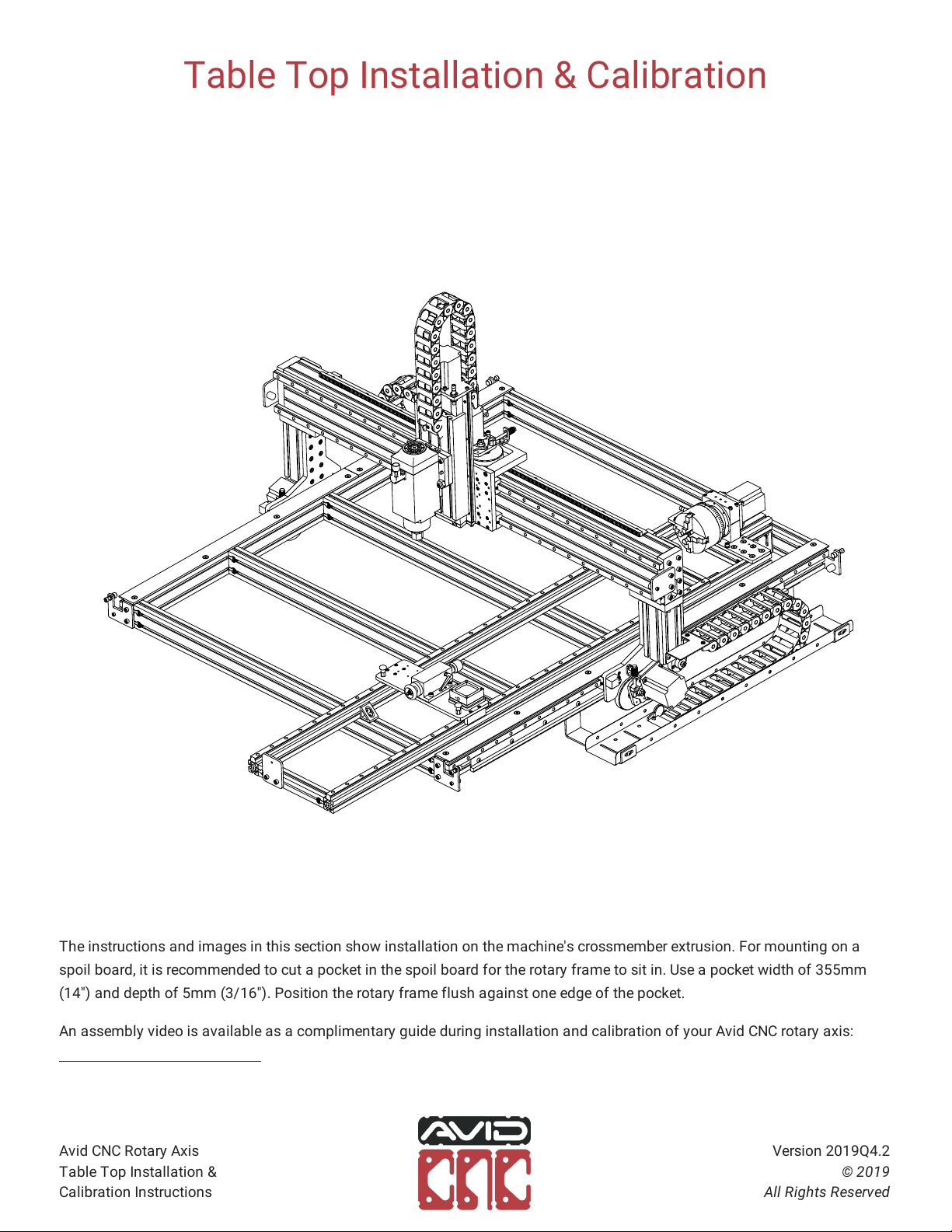
Table Top Installation & Calibration
The instructions and images in this section show installation on the machine's crossmember extrusion. For mounting on a
spoil board, it is recommended to cut a pocket in the spoil board for the rotary frame to sit in. Use a pocket width of 355mm
(14") and depth of 5mm (3/16"). Position the rotary frame flush against one edge of the pocket.
An assembly video is available as a complimentary guide during installation and calibration of your Avid CNC rotary axis:
https://youtu.be/dJZ4IF69yu0
Avid CNC Rotary Axis
Table Top Installation &
Calibration Instructions
Version 2019Q4.2
© 2019
All Rights Reserved


Parts and Tools Required
The following parts and tools will be used in Section 1.1 for installation on PRO CNC machines
QTY Part/Description Packaged In
1 CRP831-01, Bumper Plate CRP195-00-PRO-SHORT
4 40-4332 Mounting Bracket CRP195-00-PRO-SHORT
10 M8 Roll-in T-Nut CRP195-00-PRO-SHORT
2 M8 x 30mm Socket Head Cap Screw CRP195-00-PRO-SHORT
8 M8 x 16mm Button Head Cap Screw CRP195-00-PRO-SHORT
1 4080 Extrusion, 140mm (5-1/2") CRP195-00-PRO-SHORT
1 CRP190-19, Headstock Mounting Bracket CRP195-00-PRO-SHORT
2 M8 x 16mm Socket Head Cap Screw CRP195-00-PRO-SHORT
1 M12 Proximity Sensor Cable, 20' CRP190-00-BASE
1 NEMA 34 Motor Cable, 20' Rotary Electronics
1 CRP195-00-FAST: CRP195-00-PRO-SHORT
- (2) 40 Series Anchor Fastener
- (8) M8 Roll-in T-Nut
- (6) M8 x 16mm Socket Head Cap Screw
Remaining parts from this kit used in Section 1.3
Note: Rotary frames 1850mm (72") and longer will use parts packaged in CRP195-00-PRO-LONG. This kit includes an additional (4) 40-4332
mounting brackets with fasteners.
Required Tools:
- 6mm Ball-End Allen Wrench
- 5mm Allen Wrench
- Tape Measure
Avid CNC Rotary Axis
Table Top Installation &
Calibration Instructions
Version 2019Q4.2
© 2019
All Rights Reserved

1.1.1 Installation Steps
1.1.1.1
Attach a bumper plate to the tailstock end of the rotary frame as indicated.
M8 Roll-in T-Nut
CRP831-01, Bumper Plate
M8 x 16mm Socket Head Cap Screw
65mm (2-1/2")
Avid CNC Rotary Axis
Table Top Installation &
Calibration Instructions
Version 2019Q4.2
© 2019
All Rights Reserved


1.1.1.4
Attach the headstock mounting bracket to the extrusion as indicated.
M8 Roll-in T-Nut
M8 x 16mm Socket Head Cap Screw
CRP190-19, Mounting Bracket
Assembly Note
Position the bracket flush with the end of the 4080 extrusion.
Avid CNC Rotary Axis
Table Top Installation &
Calibration Instructions
Version 2019Q4.2
© 2019
All Rights Reserved


1.1.1.10
Install an additional four brackets along the middle of the rotary frame, leaving the fasteners loose.
Rotary Length Option
This step is only applicable for rotary frame lengths 1850mm (72") and longer.
78
6
5
Assembly Note
These mid-support brackets will not be tightened until the Mid-Support Calibration section.
Avid CNC Rotary Axis
Table Top Installation &
Calibration Instructions
Version 2019Q4.2
© 2019
All Rights Reserved
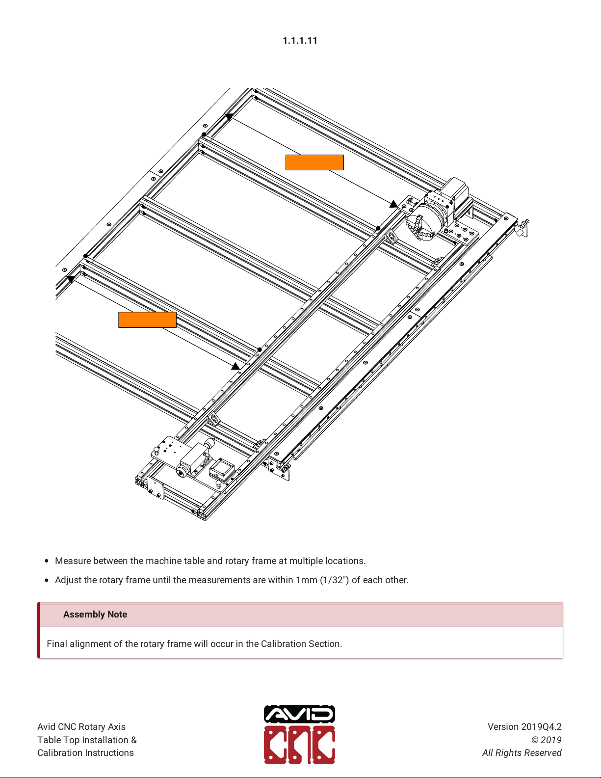
1.1.1.11
Measure between the machine table and rotary frame at multiple locations.
Adjust the rotary frame until the measurements are within 1mm (1/32") of each other.
MEASURE
MEASURE
Assembly Note
Final alignment of the rotary frame will occur in the Calibration Section.
Avid CNC Rotary Axis
Table Top Installation &
Calibration Instructions
Version 2019Q4.2
© 2019
All Rights Reserved


1.1.2 Motor & Sensor Connections
1.1.2.1
Attach the sensor and motor cable to the control box as indicated (Plug and Play Control Systems purchased prior to
October 2019 will use the "X+" sensor port).
Motor Cable
M12 Proximity Sensor Cable
"A" Sensor Port
"A" Motor Port
Assembly Note
For PRO machines purchased prior to 2019, an M12 splitter is required to connect the X+ and X- limit switches to the X- port
on the control box.
Avid CNC Rotary Axis
Table Top Installation &
Calibration Instructions
Version 2019Q4.2
© 2019
All Rights Reserved


Parts and Tools Required
The following parts and tools will be used in Section 1.2 for installation on Benchtop machines
QTY Part/Description Packaged In
1 CRP831-01, Bumper Plate CRP195-00-BTP
4 40-4332 Mounting Bracket CRP195-00-BTP
10 M8 Roll-in T-Nut CRP195-00-BTP
2 M8 x 30mm Socket Head Cap Screw CRP195-00-BTP
8 M8 x 16mm Button Head Cap Screw CRP195-00-BTP
1 4080 Extrusion, 122mm (4-3/4") CRP195-00-BTP
1 CRP190-19, Headstock Mounting Bracket CRP195-00-BTP
2 M8 x 16mm Socket Head Cap Screw CRP195-00-BTP
1 M12 Proximity Sensor Cable, 20' CRP190-00-BASE
1 NEMA 34 Motor Cable, 20' Rotary Electronics
1 CRP195-00-FAST: CRP195-00-BTP
- (2) 40 Series Anchor Fastener
- (8) M8 Roll-in T-Nut
- (6) M8 x 16mm Socket Head Cap Screw
Remaining parts from this kit used in Section 1.3
Note: Benchtop Standard installation parts will be packaged in CRP195-00-SHORT and does not include the 4080 extrusion, CRP190-19, or
CRP195-00-FAST.
Required Tools:
- 6mm Ball-End Allen Wrench
- 5mm Allen Wrench
- Tape Measure
Avid CNC Rotary Axis
Table Top Installation &
Calibration Instructions
Version 2019Q4.2
© 2019
All Rights Reserved

1.2.1 Installation Steps
1.2.1.1
Attach a bumper plate to the tailstock end of the rotary frame as indicated.
M8 Roll-in T-Nut
CRP831-01, Bumper Plate
M8 x 16mm Socket Head Cap Screw
65mm (2-1/2")
Avid CNC Rotary Axis
Table Top Installation &
Calibration Instructions
Version 2019Q4.2
© 2019
All Rights Reserved
Other manuals for CNC Rotary Axis
2
Table of contents
Other Avid Technology Industrial Equipment manuals


