PI L-412 211E1 Series User manual

L412UM0003EN ‒ 10/24/2022
User Manual
L-412.XX9211E1[B] HIGH-LOAD LINEAR STAGE
MOTION | POSITIONING

Contents
1 Legal Information.........................................................................................................4
2 About this Document..................................................................................................5
2.1 Objective and Target Group..............................................................................5
2.2 Explanation of Symbols....................................................................................5
2.2.1 Typographic Conventions................................................................. 5
2.2.2 Symbols Used.................................................................................... 5
2.3 Figures................................................................................................................6
2.4 Other Applicable Documents............................................................................6
2.5 Downloading Manuals...................................................................................... 6
3 Safety............................................................................................................................8
3.1 Intended Use......................................................................................................8
3.2 General Safety Instructions.............................................................................. 8
3.3 Organizational Measures.................................................................................. 8
3.3.1 User Manual....................................................................................... 8
3.3.2 General Personnel Qualification.......................................................9
4 Product Description................................................................................................... 10
4.1 Model Overview...............................................................................................10
4.2 Product Labeling..............................................................................................10
4.2.1 Type Plate..........................................................................................11
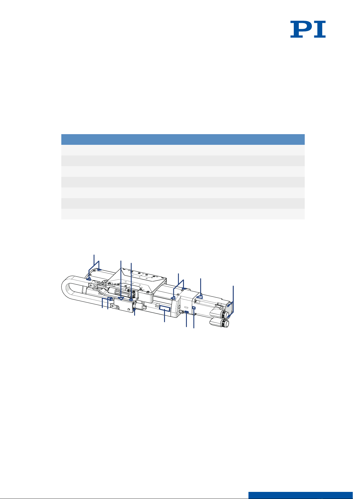
4.3 Overview.......................................................................................................... 12
4.3.1 Base Body.........................................................................................12
4.3.2 Drive..................................................................................................12
4.3.3 Holding Brake...................................................................................13
4.3.4 Drag Chain........................................................................................13
4.3.5 Purge Air System............................................................................. 13
4.4 Direction of Motion..........................................................................................15
4.5 Scope of Delivery.............................................................................................15
4.6 Suitable Electronics......................................................................................... 15
5 Unpacking.................................................................................................................. 17
6 Installation..................................................................................................................18
6.1 Mounting the L-412.xx9211E1......................................................................... 18
6.1.1 Mounting the L-412.xx9211E1 from Above.................................... 18
6.2 Connecting the L-412.xx9211E1 to the Protective Earth Conductor ............ 19
6.3 Mounting the Load.......................................................................................... 21
6.4 Connecting the L-412.xx9211E1...................................................................... 22
7 Startup and Operation.............................................................................................. 24
7.1 Starting and Operating the L-412.xx9211E1...................................................24
CONTENTS L412UM0003EN ‒ 10/24/2022
2MOTION | POSITIONING

8 Maintenance...............................................................................................................26
8.1 Maintenance Run.............................................................................................26
8.2 Lubricating....................................................................................................... 26
8.3 Cleaning............................................................................................................26
8.4 Moving the Motion Platform by Hand........................................................... 27
9 Troubleshooting......................................................................................................... 28
10 Transportation............................................................................................................29
11 Customer Service Department.................................................................................30
12 Technical Data............................................................................................................ 31
12.1 Specifications...................................................................................................31
12.1.1 L-412.xx9211E1[B].............................................................................31
12.1.2 Reference Switch Specifications.....................................................33
12.1.3 Limit Switch Specifications............................................................. 34
12.1.4 Holding Brake Specifications.......................................................... 34
12.1.5 Temperature Sensor Specifications............................................... 34
12.2 Maximum Ratings........................................................................................... 34
12.3 Ambient Conditions and Classifications........................................................34
12.4 Dimensions...................................................................................................... 35
12.5 Commutation Encoder.................................................................................... 36
13 Old Equipment Disposal........................................................................................... 37
14 European Declarations of Conformity......................................................................38
15 Appendix.................................................................................................................... 39
15.1 Pin Assignment................................................................................................39
15.1.1 Drive Connector............................................................................... 39
15.1.2 Motor Encoder Connector...............................................................40
15.1.3 Sensor Connector............................................................................ 41
16 Glossary......................................................................................................................42
CONTENTS L412UM0003EN ‒ 10/24/2022
3MOTION | POSITIONING

1 Legal Information
The following company names and brands are registered trademarks of Physik Instrumente
(PI) GmbH & Co. KG:
PI®, PIC®, NanoCube®, PICMA®, PIFOC, PILine®, NEXLINE®, PiezoWalk®, PicoCube®,
PiezoMove, PIMikroMove, NEXACT®, Picoactuator®, PInano®, NEXSHIFT®, PITOUCH®,
PIMag®, PIHera, Q-Motion®
The patents held by PI can be found in our list at https://www.physikinstrumente.com/en/
about-pi/patents.
© 2022 Physik Instrumente (PI) GmbH & Co. KG, Karlsruhe, Germany. The text, photographs,
and drawings in this manual are protected by copyright. With regard thereto, Physik
Instrumente (PI) GmbH & Co. KG reserves all rights. The use of any text, images and
drawings is permitted only in part and only when indicating the source.
Original instructions
First print: 10/24/2022
Document number: L412UM0003en, ASt
Subject to change. This manual is superseded by any new release. The latest respective
release is available for download on our website (www.pi.ws).
Publisher:
PI miCos GmbH
Freiburger Strasse 30
79427 Eschbach
Germany
www.pi.de
Customer service department:
Physik Instrumente (PI) GmbH & Co. KG
Auf der Roemerstrasse 1
76228 Karlsruhe
Germany
www.pi.de
1 LEGAL INFORMATION L412UM0003EN ‒ 10/24/2022
4MOTION | POSITIONING

2 About this Document
2.1 Objective and Target Group
This user manual contains the information needed for the intended use of the L-412.xx9211E1
and L-412.xx9211E1B (hereafter referred to as L-412.xx9211E1 or L-412).
Basic knowledge of closed-loop systems, motion control concepts, and applicable safety
measures is assumed.
2.2 Explanation of Symbols
This chapter explains the symbols and markings used by PI in their user manuals.
2.2.1 Typographic Conventions
Symbol / label Meaning
1.
2.
Action consisting of one or several steps with strict sequential order
► Action consisting of one or more steps without relevant sequential or-
der
■ Lists
p. 5 Cross-reference to page 5
RS-232 Label on the product indicating an operating element (example: RS-232
interface socket)
Start > Settings
Menu path in the PC software (example: to open the menu,
Start
and
Settings
must be clicked successively)
POS? Command line or a command from PI's General Command Set (GCS)
(example: command to get the axis position)
Device S/N
Parameter name (example: parameter where the serial number is stor-
ed)
5Value that must be entered or selected via the PC software
2.2.2 Symbols Used
Symbol / label Meaning
Hazard symbol for a hot surface
Risk of crushing
General hazard symbol
2 ABOUT THIS DOCUMENT L412UM0003EN ‒ 10/24/2022
5MOTION | POSITIONING

DANGER
Dangerous situation
Failure to comply could lead to death or serious injury.
►Precautionary measures for avoiding the risk.
WARNING
Dangerous situation
Failure to comply could lead to serious injury.
►Precautionary measures for avoiding the risk.
CAUTION
Dangerous situation
Failure to comply could lead to minor injury.
►Precautionary measures for avoiding the risk.
NOTICE
Dangerous situation
Failure to comply could lead to material damage.
►Precautionary measures for avoiding the risk.
Information
Additional information on the L-412.xx9211E1 that can affect your application.
2.3 Figures
For better understandability, the colors, proportions and degree of detail in illustrations can
deviate from the actual circumstances. Photographic illustrations may also differ and must
not be seen as guaranteed properties.
2.4 Other Applicable Documents
The devices and software tools that are mentioned in this documentation are described in
separate manuals.
Document num-
ber
Document type Product
G901M0003 User manual G-901.R519[x]
On request Manual User manual for the ACS electronics
On request Manual User manual for the ACS user software
The latest versions of the user manuals can be downloaded (p. 6) at www.pi.ws.
2.5 Downloading Manuals
Information
If a manual is missing or problems occur with downloading:
►Contact our customer service department (p. 30).
2 ABOUT THIS DOCUMENT L412UM0003EN ‒ 10/24/2022
6MOTION | POSITIONING

Downloading Manuals
1. Open the website www.pi.ws.
2. Search the website for the product number (e.g., L-412).
3. Click the corresponding product to open the product detail page.
4. Click the Downloads tab.
➔The manuals are shown under
Documentation
.
5. Click the desired manual and fill out the inquiry form.
➔The download link will then be sent to the email address entered.
2 ABOUT THIS DOCUMENT L412UM0003EN ‒ 10/24/2022
7MOTION | POSITIONING

3 Safety
3.1 Intended Use
The L-412.xx9211E1 is a laboratory device as defined by DIN EN 61010-1. It is intended for
indoor use and use in an environment that is free of dirt, oil, and lubricants.
In accordance with its design, the L-412.xx9211E1 is intended for positioning, adjusting and
shifting loads in one axis at various velocities. The L-412.xx9211E1 is not intended for
applications in areas, in which a failure would present severe risks to human beings or the
environment.
If the L-412.xx9211E1 does not have a holding brake, it is only intended for operation with a
horizontally aligned motion axis.
The intended use of the L-412.xx9211E1 is only possible when completely mounted and
connected. The thermal protection sensor built into the L-412.xx9211E1's motor must be
evaluated and monitored. The L-412.xx9211E1 must be operated with suitable electronics.
The electronics are not in the scope of delivery of the L-412.xx9211E1.
The L-412.xx9211E1 may not be used for purposes other than those stated in this user
manual. The L-412.xx9211E1 may only be used in compliance with the technical
specifications and instructions in this user manual.
3.2 General Safety Instructions
If the protective earth conductor is missing or not properly connected, risk of dangerous
touch voltages on the L-412.xx9211E1 in the event of malfunction or failure of the system. If
there are touch voltages, touching the L-412.xx9211E1 can cause serious injuries or even
death by electric shock.
►Connect the L-412.xx9211E1 to a protective earth conductor before startup (p. 19).
►Do not remove the protective earth conductor during operation.
►If the protective earth conductor has to be removed temporarily (e.g., for modification),
reconnect the L-412.xx9211E1 to the protective earth conductor before restarting.
Mechanical forces can destroy the L-412.xx9211E1.
►Avoid knocks that affect the L-412.xx9211E1.
►Do not drop the L-412.xx9211E1.
The L-412.xx9211E1 is built according to state-of-the-art technology and recognized safety
standards. Improper use of the L-412.xx9211E1 may result in personal injury and/or damage
to the L-412.xx9211E1.
►Use the L-412.xx9211E1 only for its intended purpose and when it is in perfect condition.
►Read the user manual.
►Eliminate any malfunctions that may affect safety immediately.
The operator is responsible for installing and operating the L-412.xx9211E1 correctly.
3.3 Organizational Measures
3.3.1 User Manual
►Always keep this user manual available with the L-412.xx9211E1. The latest versions of the
user manuals can be downloaded (p. 6) at www.pi.ws.
3 SAFETY L412UM0003EN ‒ 10/24/2022
8MOTION | POSITIONING

►Add all information from the manufacturer such as supplements or technical notes to the
user manual.
►If you give the L-412.xx9211E1 to a third party, also include this user manual as well as
other relevant information provided by the manufacturer.
►Only use the device on the basis of the complete user manual. Missing information due to
an incomplete user manual can lead to serious or fatal injuries and damage to equipment.
►Only install and operate the L-412.xx9211E1 after you have read and understood this user
manual.
3.3.2 General Personnel Qualification
The L-412.xx9211E1 may only be installed, started up, operated, maintained, and cleaned by
authorized and appropriately qualified personnel.
3 SAFETY L412UM0003EN ‒ 10/24/2022
9MOTION | POSITIONING

4 Product Description
4.1 Model Overview
High-load linear stage, synchronous servo motor to 320 V; travel ranges from 52 to
610 mm (see table); 400 N load capacity; 300 mm/s maximum velocity; ball screw;
incremental rotary encoder, 20000 counts/rev resolution, A/B quadrature, RS-422;
incremental linear encoder, 20 µm sensor signal period, sin/cos, 1 V peak-peak; 116
mm width; drag chain
L-412.xx9211E1B: with electromagnetic safety brake
Product number Travel range
L-412.039211E1[B] 52 mm (2")
L-412.059211E1 [B] 102 mm (4")
L-412.099211E1[B] 204 mm (8")
L-412.139211E1[B] 305 mm (12")
L-412.179211E1[B] 407 mm (16")
L-412.219211E1[B] 508 mm (20")
L-412.259211E1[B] 610 mm (24")
4.2 Product Labeling
1
1
3
12
4
2
4
5
4
6
4
Figure 1: Product labeling on the L-412.xx9211E1
4 PRODUCT DESCRIPTION L412UM0003EN ‒ 10/24/2022
10 MOTION | POSITIONING

1
1
3
12
4
2
4
5
4
6
4
Figure 2: Product labeling on the L-412.xx9211E1B
1. Warning symbol: Risk of crushing
2. Warning symbol: ESD-sensitive components
3. Warning symbol: Hot surface
4. Connector labels
5. Type plate
6. Protective earth connector
4.2.1 Type Plate
Figure 3: Type plate of the L-412.xx9211E1
1. Data matrix code (example; contains the serial number)
2. Product number (example)
3. Serial number (example), individual for each L-412.xx9211E1
4. Warning and conformity symbols (old equipment disposal (p. 37), CE mark (p. 38))
4 PRODUCT DESCRIPTION L412UM0003EN ‒ 10/24/2022
11 MOTION | POSITIONING

4.3 Overview
1
7
5
34
2
6
98
Figure 4: Elements of the L-412.xx9211E1[B]
1. Base body
2. Motion platform
3. Drive
4. L-412.xx9211E1B: Holding brake
5. Drive and rotary encoder connector
6. Purge air connector
7. Linear encoder connector
8. Grease nipple for relubricating the drive screw
9. Drag chain
4.3.1 Base Body
The base body is the basis of the positioner. The L-412.xx9211E1 is mounted onto a surface
via the base body (p. 18).
The base body comprises the following subassembly (subassemblies):
Reference switch
The reference switch (p. 33) is a sensor whose fixed position serves as the reference point
for incremental sensor signals.
Limit switches
The limit switches (p. 34) are sensors at each end of the travel range that enable the
electronics to abort motion in order to prevent the motion platform from colliding with the
mechanical hard stop.
Incremental linear encoder
The L-412.xx9211E1's linear encoder is an incremental sensor: It measures the position of the
motion platform relative to a known reference point. Linear encoders measure the actual
position directly. Therefore, drive errors such as nonlinearity, backlash or elastic deformation
cannot influence position measuring.
4.3.2 Drive
The drive generates the force that is required for the dynamics of the L-412.xx9211E1.
4 PRODUCT DESCRIPTION L412UM0003EN ‒ 10/24/2022
12 MOTION | POSITIONING

Figure 5: Drive with holding brake of the L-412
The drive comprises the following subassembly or subassemblies:
Motor
The motor generates the force required to move the fixed load.
The motor of the L-412.xx9211E1 has a commutation encoder. For information on coding,
refer to "Commutation Encoder" (p. 36).
In the case of the L-412.xx9211E1, overheating is prevented using temperature
sensors (p. 34).
Drive screw
The drive screw converts the rotary motion of the drive to linear motion of the motion
platform.
Rotary encoder
The rotary encoder measures the motor shaft's angle of rotation. This signal can be used by
suitable electronics for commutating the motor .
4.3.3 Holding Brake
For L-412.xx9211E1B models:
The holding brake blocks the drivetrain at rest.
The holding brake is designed for holding only and is not suitable for continuous braking
during operation.
The holding brake blocks in a zero voltage state.
4.3.4 Drag Chain
The drag chain (also: energy chain or energy supply chain) guides and protects the
L-412.xx9211E1's flexible cables and lines.
4.3.5 Purge Air System
The purge air system protects the drive and guides of the L-412.xx9211E1 against
surrounding dust.
The purge air system comprises the following subassembly (subassemblies):
4 PRODUCT DESCRIPTION L412UM0003EN ‒ 10/24/2022
13 MOTION | POSITIONING

Passive dust protection
The passive dust protection consists of covering strips that seal the openings on the side of
the L-412.xx9211E1's base body and therefore reduces the amount of dust that can penetrate.
Active dust protection
The active dust protection consists of a purge air connector on the base body of the
L-412.xx9211E1, which creates a slight overpressure in the L-412.xx9211E1 and therefore
reduces the amount of dust that can penetrate.
4 PRODUCT DESCRIPTION L412UM0003EN ‒ 10/24/2022
14 MOTION | POSITIONING

4.4 Direction of Motion
Figure 6: Bewegungsrichtung des L-412 bei positiver Kommandierung
4.5 Scope of Delivery
Product number Description
L-412.xx9211E1 Linear stage according to the order (p. 10)
For L-412.xx9211E1 with xx = 03, 05, 09, 13:
L412B0048
Mounting kit for mounting the
L-412.xx9211E1, consisting of
■10 socket head screws, ISO 4762 M6×30
■2 dowel pins, ISO 2338 4h8×12
■10 flat washers, ISO 7092, D11 d6.4 h1, 6
mm
For L-412.xx9211E1 with xx = 17, 21, 25:
L412B0049
Mounting kit for mounting the
L-412.xx9211E1, consisting of
■16 socket head screws, ISO 4762 M6×30
■2 dowel pins, ISO ISO 2338 4h8×12
■16 flat washers, ISO 7092, D11 d6.4 h1, 6
mm
MP187EK Short instructions for positioners with elec-
tric motors to 320 V
4.6 Suitable Electronics
The L-412.xx9211E1 must be connected to suitable electronics that supply the necessary
voltage for operating and if required, to evaluate the sensor and limit switch signals. The
following electronics are suitable:
Product number Description
G-901.R519[x] ACS controller with ACS driver module, 2 / 3 / 4 axes, intermediate cir-
cuit voltage 96 V / 2000 W
On request ACS modular controller
Also compatible with other 3rd-party controllers and servo drivers
Note that the cables required for connecting the L-412.xx9211E1 to the electronics must be
ordered separately.
4 PRODUCT DESCRIPTION L412UM0003EN ‒ 10/24/2022
15 MOTION | POSITIONING

5 Unpacking
Unpacking the L-412.xx9211E1
1. Unpack the L-412.xx9211E1 with care. Hold the L-412.xx9211E1 by its base body only.
2. If the L-412.xx9211E1 was supplied with ESD protective caps on the connectors: Do not
remove the ESD protective caps.
3. Compare the contents with the scope of delivery according to the contract and the
delivery note.
4. Inspect the contents for signs of damage. If any parts are damaged or missing, contact
our customer service department (p. 30) immediately.
5. Keep all packaging materials in case the product needs to be returned.
5 UNPACKING L412UM0003EN ‒ 10/24/2022
17 MOTION | POSITIONING

6 Installation
6.1 Mounting the L-412.xx9211E1
CAUTION
Risk of crushing by moving parts!
Risk of minor injuries from crushing between the moving parts of the L-412.xx9211E1 or the
load and a fixed part or obstacle.
►Use safeguards to protect limbs in areas where they could be caught by moving parts.
►Maintain the safety distances according to DIN EN ISO 13857 when installing protective
structures.
NOTICE
Damage due to collisions!
Collisions can damage the L-412.xx9211E1, the load to be moved, and the surroundings.
►Make sure that collisions are not possible between the L-412.xx9211E1, the load to be
moved, and the surroundings in the motion range of the L-412.xx9211E1.
►Do not place any cables or other objects in areas where they could be caught by moving
parts.
NOTICE
Damage due to mechanical stress on the cable!
The cable will break from excessive bending or crushing. A broken cable will lead to failure
of the L-412.xx9211E1 or damage to the L-412.xx9211E1 or the electronics.
►Install the L-412.xx9211E1 so that the cable cannot be bent or crushed too strongly.
6.1.1 Mounting the L-412.xx9211E1 from Above
Overview
Figure 7: Mounting the L-412.xx9211E1 onto an underlying surface
Tools and Accessories
■Mounting kit for mounting the L-412.xx9211E1 (p. 15)
6 INSTALLATION L412UM0003EN ‒ 10/24/2022
18 MOTION | POSITIONING

■Suitable torque wrench
Requirements
✓You have read and understood the general safety instructions (p. 8).
✓You have provided a suitable underlying surface with the holes necessary for the screws
and if required, locating pins. For the position and depth required for the holes, see
"Dimensions" (p. 35).
■The surface flatness is ≤ 2 μm.
■For applications with large temperature fluctuations: The surface should have the
same or similar thermal expansion properties as the L-412.xx9211E1.
✓You have accounted for the space required to route cables according to regulations and
without bending them.
■The cable routing does not obstruct the motion of the L-412.xx9211E1.
■The cable does not rub against sharp edges during movements of the L-412.xx9211E1.
Mounting the L-412.xx9211E1 from above
1. Optional: Insert the locating pins into the corresponding holes in the underlying surface.
2. Align the L-412.xx9211E1 on the underlying surface so that the corresponding mounting
holes in the L-412.xx9211E1 and underlying surface are in line.
3. Put the L-412.xx9211E1 onto the underlying surface so that the locating pins can be
inserted into the corresponding locating holes of the L-412.xx9211E1.
4. If necessary: Allow access to the mounting holes in the base body of the L-412.xx9211E1.
Possible measures:
■Starting and operating the positioner (p. 24) temporarily, and commanding the
motion platform to a suitable position
■Moving the platform by hand (p. 27)
5. Tighten all screws in the mounting holes.
Recommended torque: 3 Nm
6. If necessary: Repeat steps 4 and 5 for all concealed mounting holes.
7. Check that the L-412.xx9211E1 is sitting firmly on the underlying surface.
6.2 Connecting the L-412.xx9211E1 to the Protective Earth Conductor
The L-412.xx9211E1 must be connected to the protective earth conductor via the drive
connector: For this purpose, the protective earth connector on the motor plug on the drive
electronics side must be connected to an earth connection.
If the load needs to be connected to the protective earth conductor, the L-412.xx9211E1's
base body must also be connected to the protective earth conductor. In this case, connect
the load and base body to the protective earth conductor separately.
The following description offers an example of how to connect the protective earth
conductor to the base body of the L-412.xx9211E1.
6 INSTALLATION L412UM0003EN ‒ 10/24/2022
19 MOTION | POSITIONING

DANGER
Risk of electric shock if the protective earth conductor is not connected!
If the protective earth conductor is missing or not properly connected, risk of dangerous
touch voltages on the L-412.xx9211E1 in the event of malfunction or failure of the system. If
there are touch voltages, touching the L-412.xx9211E1 leads to serious injuries or death by
electric shock.
►Connect the L-412.xx9211E1 to a protective earth conductor before startup.
►Do not remove the protective earth conductor during operation.
►If the protective earth conductor has to be removed temporarily (e.g., for modifications),
reconnect the L-412.xx9211E1 to the protective earth conductor before restarting.
Information
►Pay attention to the applicable standards for connecting the protective earth conductor.
Overview
Figure 8: Protective earth connector on the L-412.xx9211E1
1. Protective earth connector on the L-412.xx9211E1 indicated by the protective earth symbol
2. Lock washer
3. Flat washer
4. Cable lug of the protective earth conductor
5. Screw, M4×8 ISO 7045
Tools and Accessories
■Suitable protective earth conductor:
■Cable cross section ≥ 0.75 mm2
■Contact resistance <0.1 Ω at 25 A at all points relevant for attaching the protective earth
conductor
■Suitable screwdriver
■Optional: Suitable aid (e.g., liquid adhesive) for securing the screw connection
Requirements
✓You have read and understood the general safety instructions (p. 8).
Connecting the L-412.xx9211E1's Base Body to the Protective Earth Conductor
1. If necessary, attach a suitable cable lug to the protective earth conductor.
2. Attach the cable lug of the protective earth conductor to the protective earth connector of
the L-412.xx9211E1 as shown in the illustration.
3. Tighten the screw with a torque of 1.2 Nm to 1.5 Nm.
6 INSTALLATION L412UM0003EN ‒ 10/24/2022
20 MOTION | POSITIONING
This manual suits for next models
3
Table of contents
Other PI Industrial Equipment manuals

PI
PI S-340 Manual

PI
PI L-417 9232B Series User manual

PI
PI L-417 9054B Series User manual

PI
PI VT-80 User manual

PI
PI L-412.XX9025E1B Series User manual

PI
PI NEXACT Stage N-565 Series User manual

PI
PI L-412.039211E0 User manual

PI
PI L-417 9025E1B Series User manual

PI
PI L-412 9054 Series User manual

PI
PI L-412 9232B Series User manual