Avid Water Systems KLX2 Series Quick start guide

First Sales, LLC
12630 US Highway 33 N
Churubusco, IN 46723
Phone (260) 693-1972 Fax (260) 693-0602
KLX2-KLX2E Instruction Manual 190117.docx
KLX2 & KLX2E Series
Catalytic Filter System
Installation Instructions and Owner’s Manual

1
Pre-installation Instructions
Page 2
General Installation
Page 4
Installation Instructions
Page 5
KLX2 Timer Operation
Page 8
KLX2E Display and Operation
Page 10
KLX2E Setting Time of Day
Page 11
KLX2E Additional Programming
Page 12
Specifications
Page 13
Component Parts Breakdown & List
Page 14
KLX2 Control Valve Breakdown
Page 15
KLX2 Control Valve Parts List
Page 16
KLX2E Control Valve Breakdown
Page 17
KLX2E Control Valve Parts List
Page 18
Troubleshooting
Page 19
Control Valve Wiring Diagram
Page 21
Ten Year Limited Warranty
Page 22
Table of Contents

2
Description of the iron filtration system
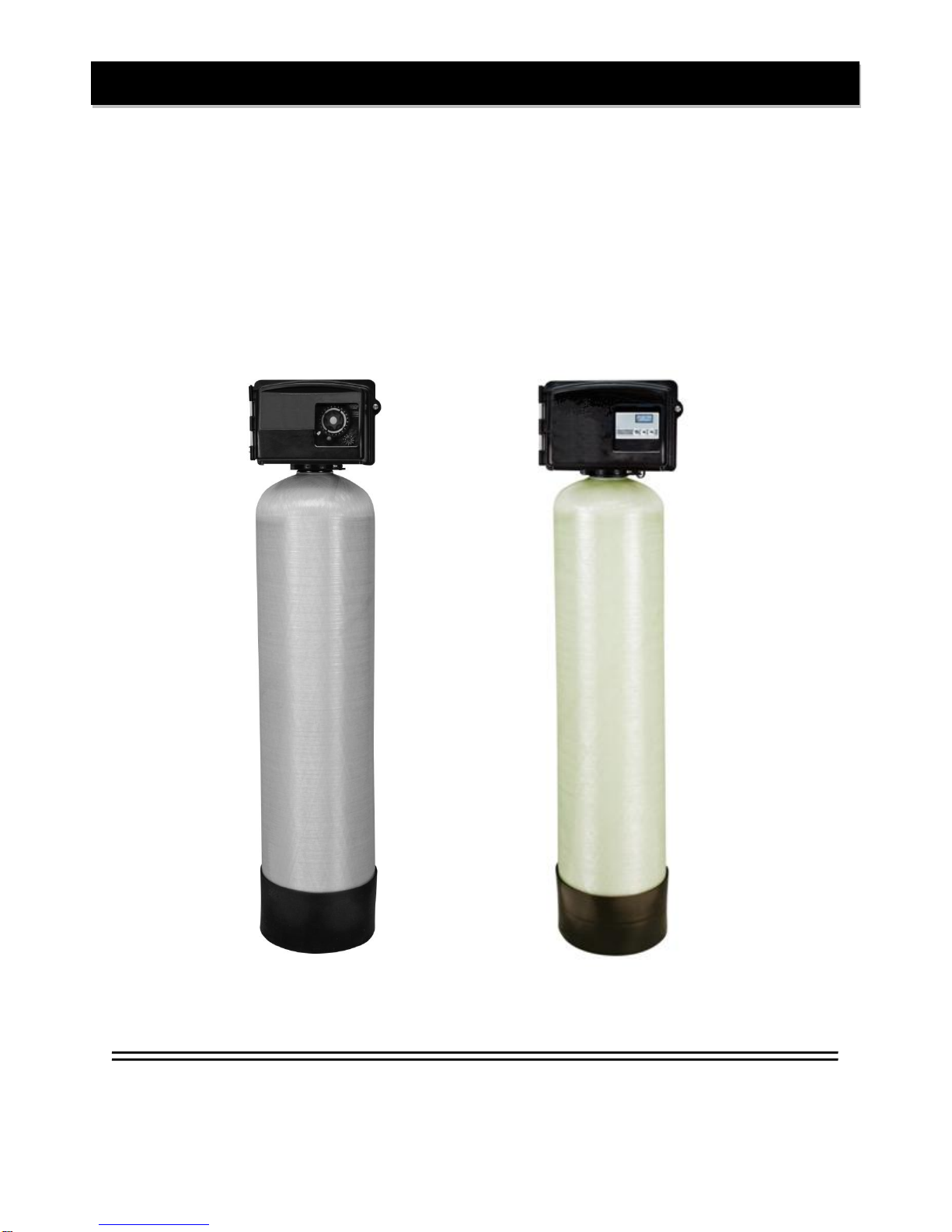
The KLX2 catalytic filtration system includes a single filtration tank with a pocket of air and a backwashing
control valve. Incoming water flows into the control valve and is directed into the filtration tank. Exposure to the
air in this tank will start oxidizing the iron which is then trapped by the media. The iron/sulfur-free water then
returns to the control valve where it is directed into the service lines.
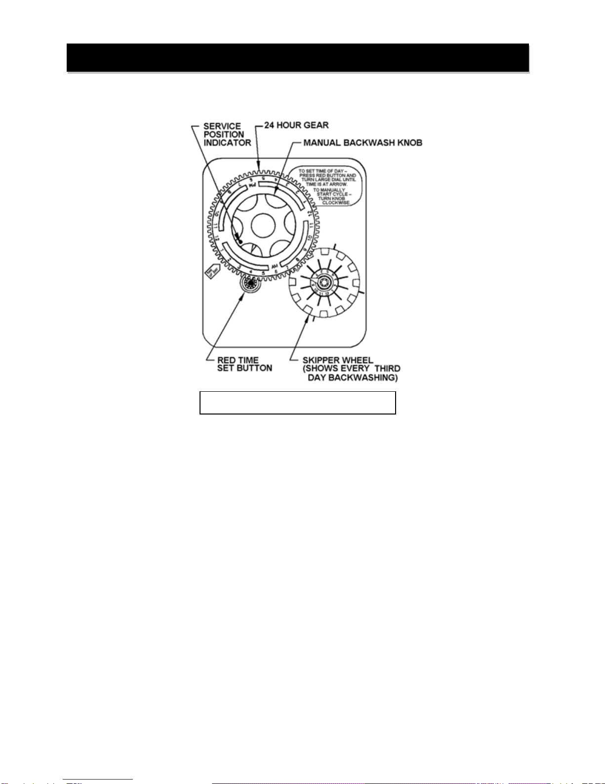
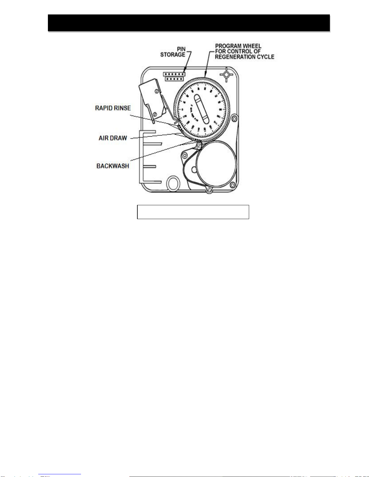
Periodically the control valve will go through a backwash cycle. This cycle will typically begin at 1:00 A.M.
flushing the accumulated iron to the drain. Part of this backwashing process includes an air draw cycle which
will replenish the pocket of air in the filter tank and prepare the unit for the next period of service.
Water Quality
While the KLX2 filter will perform under a variety of water qualities there are a few things that need to be
considered to ensure satisfactory performance. The water should be tested to determine the concentration, or
levels of the items listed below.
pH - A measurement of the acidity of the water. pH is reported on a scale from 0 to 14. Neutral water has a pH
of 7.0, lower values indicate acidic water. The KLX2 catalytic filter performs best when the pH is 7.0, or higher.
pH values below 7.0 require a special media blend in the filter in order to elevate the pH for proper iron
oxidation.
Iron - A naturallyoccurring metallic element. Iron concentrations in excess of 0.3 milligrams/liter (mg/l) combine
with oxygen causing orange or red (rust) stains on plumbing fixtures. Iron naturally exists in some water
sources in either clear water (ferrous) state, red water (ferric) state or bacterial form. The KLX2 catalytic filter
can reduce any of these forms of iron.
Manganese - A naturally occurring metallic element. Manganese concentrations as low as 0.05 milligrams/liter
(mg/l) can combine with oxygen to cause dark brown or black staining on fixtures. Additionally, manganese can
cause an odor in the water similar to a “rotten egg” smell. The KLX2 catalytic filter reduces manganese as well
as iron, however, manganese oxidation requires the pH of the water to be elevated to 8.2 or higher.
Tannin - A naturally occurring humic acid. Tannin is an acid caused by water passing through decaying
vegetation. Coffee and Tea are prime examples of tannin in water. As hot water passes over the coffee beans,
or tea leaves, the tannin is extracted causing color and flavor in the water. Tannin concentrations as low as 0.3
milligrams per liter can cause a yellow discoloration in the water and may interfere with the KLX2 filter’s long-
term abilityto function properly as the media becomes coated with the tannic acid.
Hydrogen Sulfide - A naturally occurring gas. Hydrogen sulfide, more commonly referred to as sulfur gas,
causes a distinct odor similar to “rotten eggs.” Due to its gaseous nature, hydrogen sulfide must be tested at the
well site within 1 minute of drawing the sample. If a water sample has been sitting for a while the sulfur gas will
dissipate and cause the hydrogen sulfide test to be lower than the actual concentration. If sulfur is present, the
filter should be set to backwash more frequently to prevent the gas from building up.
Pre-installation Instructions

3
Water Supply
Unlike other iron filters that do not use chemicals to oxidize the iron, the KLX2 catalytic filter does not require
additional devices such as air compressors, venturis, solenoids, pressure switches or pressuretanks. This filter
will function properly when the water supply is furnished by a jet pump (5 gpm minimum), submersible pump,
variable speed (constant pressure) pump or community water supply. As with all other filter systems, however,
it is imperative that the well pump provides enough flow rate for the filter to adequately backwash. In order to
ensure sufficient backwash flow rate the following pumping rate test should be performed prior to installing the
iron filter.
1. Make certain no water is being drawn in the house.
2. Open spigot nearest pressure tank.
3. When well pump starts, close spigot and measure time (in seconds) to refill pressure tank (well pump
turns back off). This is Cycle Time.
4. Using a container of known volume, draw water from pressure tank and measure how manygallons
until the pump turns back on again. This is Draw Down.
5. Calculate pumping rate bydividing draw down by cycle time and multiplying by 60.
Draw Down (gallons)
X
60
=
Pumping Rate (gallons per minute)
Cycle Time (seconds)
Example: Draw down is 8 gallons
Cycle time is 65 seconds
Location Considerations
The proper location to install the KLX2 filter will ensure optimum filter performance and satisfactory water
quality. The following factors should be considered in selecting the location of the iron filter.
1. The filter should be installed after the pressure tank (private well system only).
2. The filter should be installed as close as possible (preferably within 15’) to an adequate floor or
laundry drain capable of handling the backwash cycle volume and flow rate (refer to unit
specifications).
3. All water conditioning equipment should be installed prior to the water heater. Water temperatures
exceeding 100°F can damage the internal components of the control valve and filter tank. An
expansion tank may need to be installed in the line to the water heater in order to allow for thermal
expansion and comply with local plumbing codes.
4. The filter should not be subject to freezing temperatures.
5. The filter should be installed before a water softener (if required).
6. Never install a cartridge type filter prior to the KLX2 iron filter. Any cartridge or in-line filter (if
desired) should be installed after KLX2 filter. This will prevent restricting the water flow and
pressure available for backwash.
7. Appliances requiring extended periods of continuous or high flow water use (i.e. geothermal heat
pumps, swimming pools, lawn irrigation, outside hose bibs, etc.) should bypass the filter and a
spring check valve should be installed on the filter inlet to prevent backflow of air from the filter tank
(see installation diagram Fig. 1).
8 gallons
X
60
=
7.4 gpm (gallons per minute)
65 seconds
Pre-installation Instructions (cont.)

4
GENERAL INSTALLATION & SERVICE WARNINGS
The water conditioner is not designed to support the weight of plumbing.
Do not use Vaseline, oils, other hydrocarbon lubricants or spray silicone anywhere. A silicone lubricant may be
used on black “O” Rings. This will allow ease of installation and decrease chance of rolling from the bypass and
tank connections. Avoid any type of lubricants, including silicone, on red or clear lip seals.
Do not use pipe dope or other sealants on threads. Teflon®tape must be used on the threads of the drain line
connection. Teflon®tape is not used on any connection where “O” Ring seals are used
NOTE: If the plumbing system is used as the ground leg of the electric supply, continuity should be maintained
byinstalling ground straps around any non-conductive plastic piping or bypass used in the installation.
Make sure the filter is not installed backwards. The filter will not function properly if installed backwards and filter
media may be forced into the water lines. Arrows molded into the valve body and into the bypass indicate the
direction of flow.
Typical Installation
Water
Heater
Water Softener
KLX2/KLX2E
Filter
UntreatedWater
UntreatedWaterfor
geothermal heat pumps,
swimming pools lawn
irrigation, etc.
Cold softened water
Hot softened water
FilteredHardWater
FIGURE 1: Typical Installation
Spring Check
Valve
Grounding Strap
FIGURE 3: Bypass Valve
FIGURE 2: KLX2/KLX2E Top View
Outlet to service
DLFC RetainerClip
Drain Line Elbow
General Installation
Inlet from water supply

5
STEP 1: If media is already loaded in filter tank proceed to Step 4. Otherwise, place red pipe cap (if
provided) or a piece of tape over the end of the distributor tube to prevent media from entering
the distributor tube during media filling. Make sure the distributor tube is centered and not
suspended off the bottom of the tank by gravel (pre-loaded).
STEP 2: Use the fill funnel provided to add the provided media to the filter tank. Do not overfill the tank.
At least 14” of freeboard (empty space) is required at the top of the media tank to allow for
proper bed expansion during backwash.
STEP 3: Clean any media out of the tank threads and remove pipe cap or tape from distributor tube.
STEP 4: If the control valve is already installed on the filter tank; unscrew the control valve. Using a
garden hose or bucket and media funnel; fill the mineral tank with water to allow the media
time to saturate.
STEP 5: Make sure control valve pilot tube and tank thread o-rings are lubricated with silicone lubricant
and screw the control valve onto the filter tank.
STEP 6: Shut off water at main supply. Relieve pressure by opening nearest faucet. On private well
systems, turn off power to pump and drain pressure tank. SHUT OFF POWER OR FUEL
SUPPLY TO WATER HEATER.
STEP 7: Cut main supply line as required to fit plumbing to inlet and outlet of bypass valve. DO NOT
PLUMB INLET AND OUTLET BACKWARDS. Piping should support control valve in an
upright position. Do not apply heat to any fitting attached to the bypass or control valve.
STEP 8: Use the provided drain line tubing (NO VINYL TUBING) to run drain line from control valve
discharge fitting to floor drain or sump pit capable of handling the backwash rate of the filter
(refer to specifications and flow rate on page 12). DISCHARGE END OF THE DRAIN LINE
MUST BE FIRMLY SECURED! Failure to properly secure the drain line will result in the drain
line “whipping” and possibly flooding the area causing water damage. There must be an air
gap at the end of the drain line to prevent siphoning of waste water and meet plumbing code.
Total length of drain line should be 15’ or less. AVOID OVERHEAD DRAINS.
Installation Instructions

6
STEP 9: Be sure the bypass valve is in the “BYPASS” position (see figure 3, page 4).
Plug the power cord(KLX2) or transformer (KLX2E) into a non-switched electrical outlet.
Open main supply valve or turn on power to the pump or private well system. Check for leaks
and correct as needed.
STEP 10: KLX units require you to set the current time of day by depressing the red Time Set Button
(Figure 4a) and turning the 24 Hour Gear (Figure 4a) to the desired time (note AM and PM).
For the KLX2E unit see page 11 for Setting Time of Day.
STEP 11: Time of Regeneration is factory set to 1:00 A.M. To adjust the time of regeneration on KLX2
units (if needed):
a) Unplug control valve from electrical outlet
b) Locate three screws (Figure 4b, page 6) behind the Manual Backwash Knob
(Figure 4a, Page 6) by pushing the red Time Set Button (Figure 4a, page 6) and
rotating the 24 Hour Gear (Figure 4a, page 6) until each screw appears in the cut out
portion of the Manual Backwash Knob.
c) Loosen each screw slightly to release pressure on the 24 Hour gear time plate.
Continued on next page…
KLX2 BACKWASH TIMER
CONTROL
FIGURE 4a: Timer in Service Position
FIGURE 4b: Adjusting Time of Regeneration
Installation Instructions (cont.)

7
d) Continue depressing the red Time Set Button and rotate the 24 Hour Gear to
expose the Regeneration TimePointer (Figure 4a, page 6) in the cut out portion of the
Manual Backwash Knob. Keep the Regeneration Time Pointer visible in the cut out
while rotating only the time plate until the desired time of regeneration (note AM and
PM) is aligned with the Regeneration Time Pointer. NOTE: subtract 136 minutes from
the desired time for the start of backwash to determine where the Regeneration Timer
Pointer should point.
e) Continue depressing the red Time Set Button and rotate the 24 Hour Gear along
with the Time Plate until each screw has been exposed in the cut out portion of the
Manual Backwash Knob and re-tightened. DO NOT OVERTIGHTEN. Make certain
that the backwashing filter DOES NOT regenerate at the same time with any other
water treatment equipment.
Time of Regeneration for KLX2E units can be changed (factory set for 1:00 AM). To change
refer to Additional Programming on page 13.
STEP 12: Advance control valve to backwash position:
KLX2 Slowlyrotate the Manual Backwash Knob (see Fig. 4a) clockwise until two clicks are
heard. This is the “BACKWASH” position.
KLX2E Press and hold down the center “ADVANCE” button until “GO TO BW” appears on
the screen (see Fig. 6, page 11). Wait until the valve reaches the backwash position before
going to STEP 11 (a countdown timer willappear on the display).
Unplug the control valve from the electrical outlet to keep it in the backwash position.
STEP 13: Refer to Figure 3 (page 4) for appropriate bypass valve operation. Rotate bypass lever of
stainless steel bypass ¼ of the way to “Service” allowing unit to fill slowly. You should hear
water trickling into the mineral tank. Filling the mineral tank in this position will force any
trapped air to the drain. When all air has been purged from the system and only water is
running to the drain, slowly open the bypass valve fully to the service position and
allow the unit to backwash until the drain water is clear of any cloudiness due to media
fines.
STEP 14: Plug the control valve back into the electrical outlet and allow it to complete the remainder of
the regeneration cycles automatically. Please verifythe unit draws air during the air drawcycle
byfeeling for suction at the end of the white check valve attached to the control valve.
STEP 15: Turn power or fuel supply back on to water heater.
Installation Instructions (cont.)

8
How to set Time of Day:
1. Press and hold the red button to disengage the drive gear.
2. Turn the large 24 hour gear until the actual time of day is at the time of daypointer.
3. Release the red button to again engage the drive gear.
How to set the Days of Backwash:
1. Rotate the skipper wheel until the number 1 is at the red pointer.
2. Each number represents a day. The number bythe red pointer is tonight.
3. Slide the metal tabs outward on the desired days of regeneration.
The KLX2 Filter should be set to backwash a minimum of every third day.
How to Manually Initiate a Backwash Cycle:
1. Grab the manual regeneration knob and turn clockwise.
2. The drive gear will engage the program wheel and make a complete revolution through the
backwash cycle.
3. The backwash knob will make a complete revolution and return to the home position after the
backwash cycle.
KLX2 Timer Operation
FIGURE 4: Front of Timer Assembly

9
How to Change the Length of Backwash Cycles:
All cycles have been factory set and should not need adjustment. If local conditions require different
cycle lengths, however, the following procedures should be followed. The end of the program wheel has been
used for backwash cycles to minimize the amount of time that pressure will be applied to the air draw check
valve.
1. Grasp top left corner of timer assembly and pull to swing timer open and expose the program
wheel.
2. Remove program wheel from timer by squeezing retaining lugs in center of program wheel.
Maneuver program wheelaway from micro switch arms and timer assembly.
3. RAPID RINSE cycle may be lengthened byadding pins at the end of the program wheel. Each pin
represents 2 minutes of rapid rinse time. The rapid rinse time MUST onlybe increased byshifting
both the backwash pins and air draw holes an equal number of positions counter-clockwise on the
program wheel.
4. AIR DRAW cycle maybe lengthened byincreasing the number of holes between the two sets of
pins. Each hole represents 2 minutes of air draw time. The air draw time MUST onlybe increased
bymoving the backwash pins counter-clockwise on the program wheel. Ensure that lengthening
the air draw time does not decrease either the backwash or rapid rinse times.
5. BACKWASH cycle maybe lengthened by adding pins in a counter-clockwise direction to first set of
pins on program wheel. Each pin willequal 2 minutes of backwash time. Ensure that adding pins
does not decrease air draw time.
6. Reinstall the program wheel on the retaining lugs bymaneuvering past the micro switch arms.
7. Close and latch the timer assembly. Ensure that the retainer snaps into the hole in the backplate
and all electrical wiring is ABOVE the timer post.
FIGURE 5: Back of Timer Assembly
KLX2 Timer Operation (cont.)

10
SET BUTTON
1. Press and hold “Set Button”for 5 seconds to enter Programming Mode.
2. When valve is in Programming Mode, press “Set Button”to confirm setting and advance to next
menu option.
ADVANCE BUTTON
1. Press and hold “Advance Button”for 5 seconds to initiate an immediate regeneration cycle.
2. Press and release “Advance Button”during a regeneration cycle to immediatelyadvance the valve
to the next step in the regeneration process.
3. When the valve is in Programming Mode, press the “Advance Button”to move the cursor.
UP BUTTON
1. When the valve is in the Programming Mode, press “Up Button”to adjust setting.
KLX2E Display and Operation
Advance Button
FIGURE 6: Display Panel

11
Enter Programming Mode:
Press and Hold the SET Button for 5 seconds.
KLX2E Setting Time of Day
Use Up Button to set current hour
Use Up Button to set current minute
Use Up Button to set AM/PM
Exit Programming Mode

12
Press and HOLD the UP button for 5 seconds to enter the programming mode.
KLX2E Additional Programming
Use Up Button to set frequency of regeneration. KLX units must be regenerated at
least every 3 days.
Use Up Button to set the hour for time-of-regeneration. NOTE: Factory setting is
1:00 AM.
Use Up Button to set minutes for time-of-regeneration.
Use Up Button to set AM or PMfor time-of-regeneration.
The DEFAULT setting is not used for KLX units and must be set to OFF.
Use Up Button to set length of BACKWASH cycle. (factory set for 8 minutes)
Use Up Button to set length of AIR DRAW cycle. (factory set for 14 minutes)
Use Up Button to set length of BRINE REFILL cycle. Not usedon KLXunits
(factory set for 0 minutes)
Use Up Button to set length of FAST RINSE cycle. (factory set for 8 minutes)
Use Up Button to set the CONTROL TYPE to TC (time clock, factory default).

13
KLX2E-10
KLX2E-15
KLX2E-20
KLX2E-30
MEDIA VOLUME, cu. ft.
1.0
1.5
2.0
3.0
GRAVEL UNDERBED, lbs.
20
20
30
50
SERVICE FLOW RATES, gpm
Continuous
3
4
5
9
Peak
5
6
8
13
PRESSURE LOSS1, psi
@ Continuous Flow Rate
5
5
7
10
@ Peak Flow Rate
8
8
11
15
REGEN. FLOW RATES, gpm
Backwash
7.0
9.0
10.0
16.0
Air Draw and Slow Rinse
0.9
0.9
0.9
0.9
Rapid Rinse
7.0
9.0
10.0
16.0
SERVICE PIPE SIZE, in.
1
1
1
1
FACTORY REGEN. SETTINGS
Backwash, minutes
8
8
8
8
Air Draw & Rinse, minutes
14
14
14
14
Rapid Rinse, minutes
8
8
8
8
Total Water Used, gallons
125
157
173
269
DIMENSIONS, in.
Mineral Tank (diameter x height)
10 x 54
12 x 48
13 x 54
16 x 65
Overall, length x width x height, in.
12x 15 x 64
12x 15 x 58
13x 15 x 64
16x 16 x 75
GENERAL REQUIREMENTS:
Water Temperature: 40° F –100° F
Water Pressure: 30 psi –100 psi
Electrical Requirements: 110V/60Hz
KLX2-10
KLX2-15
KLX2-20
KLX2-30
MEDIA VOLUME, cu. ft
1.0
1.5
2.0
3.0
GRAVEL UNDERBED, lbs.
20
20
30
50
SERVICE FLOW RATES, gpm
Continuous
3
4
5
9
Peak
5
6
8
13
PRESSURE LOSS1, psi
@ Continuous Flow Rate
5
5
7
10
@ Peak Flow Rate
8
8
11
15
REGEN. FLOW RATES, gpm
Backwash
7.0
9.0
10.0
16.0
Air Draw and Slow Rinse
0.9
0.9
0.9
0.9
Rapid Rinse
7.0
9.0
10.0
16.0
SERVICE PIPE SIZE, in.
1
1
1
1
FACTORY REGEN. SETTINGS
Backwash, minutes
8
8
8
8
Air Draw & Rinse, minutes
14
14
14
14
Rapid Rinse, minutes
8
8
8
8
Total Water Used, gallons
125
157
173
269
DIMENSIONS, in.
Mineral Tank, diameter x height
10 x 54
12 x 48
13 x 54
16 x 65
Overall, length x width x height
12x 15 x 64
12x 15 x 58
13x 15 x 64
16x 16 x 75
Specifications

14
Ref #
Part Number
Description
1
KLX2-10 Vlv AssyW/BP
KLX2E-10 Vlv Assy W/BP
Complete Valve Assy w/ Bypass for:
KLX2-10
KLX2-15, KLX2-20, KLX2-30
KLX2E-10 Vlv Assy W/BP
KLX2E-20 Vlv Assy W/BP
Complete Valve Assy w/ Bypass for:
KLX2E-10
KLX2E-15, KLX2E-20,KLX2E-30
2
D100S-48
D100S-54
D100S-65
Distributor Tube, 1” x 48”, KLX2-15 & KLX2E-15
Distributor Tube, 1” x 54”, KLX2-10, KLX2E-10,
KLX2-20 & KLX2E-20
Distributor Tube, 1” x 65”, KLX2-30 & KLX2E-30
3
MTP1054N
MTP1248N
MTP1354N
MTP1665N-4.0*
Mineral Tank, 10” x 54”, KLX2-10 & KLX2E-10
Mineral Tank, 12” x 48”, KLX2-15 & KLX2E-15
Mineral Tank, 13” x 54”, KLX2-20 & KLX2E-20
Mineral Tank, 16” x 65”, KLX2-30 & KLX2E-30
*(also required: SF4821-2 bushing 2.5” x 4.0”)
4
K05P
½ cubic foot pail catalytic media
(see specifications for recommended volume)
5
QC20
QC50
20 pounds ¼” x 1/8” gravel
50 pounds ¼” x 1/8” gravel
(see specificaitons for recomemnded voume)
6
JG-38CV
3/8” Check Valve
6
1
2
3
4
Component Parts Breakdown & List
5

15
KLX2 Control Valve Breakdown

16
REF #
Part Number
Description
REF #
Part
Number
Description
A
60041SS
Stainless Steel Bypass, 1”
FPT
10
17776
Injector Body Plastic
B
60900-41
Coupling Kit
11
14805
Injector Body Gasket
C
JG-38CV
Check Valve, 3/8” Tube
12
10328
90 Degree Elbow (1/4 Pipe x
3/8 Tube)
D
60011-050ASSY
Brine Valve, 1650 Short
Stem, 0.5 BLFC with Tube
13
12408
7.0 gpm DLFC
(KLX2-10 )
E
60705-70A
7.0 gpm DLFC Elbow
(KLX2-10 )
15
19936
Base Seal (2510)
60705-00A
Blank DLFC Elbow
(KLX2-15, 20 & 30)
16
19322
2510 Adapter Base
F
60121
Seal and Spacer Kit
17
19197
Slip Ring
G
60090
Piston Assembly
18
18303
Tank O-Ring, 2510 Valve
H
FV2510-1PH
Power Head Assembly,
2510 TC with Cover
19
13304
Distributor O-Ring, -121
I
60050-21
Drive Motor Assembly
20
13030
Distributor Retainer
J
60160-10
Drive Cam Assembly, STF
22
13911
Main Drive Gear
K
60304-13
Timer Assembly, 3200,
12 Day, STF, 120/60
23
18743-1
Timer Motor, 120v/60Hz,
2510/5600 Valve
1
14105
Bypass Valve Seal, Single
Lever
24
15320
Micro Switch, Homing
2
13305
Coupling O-Ring, -019
25
10896
Micro Switch, Step
4
10692
Injector cover screw
2510 valve
26
10218
Micro Switch, Drive Motor
5
11893
Injector Cover
27
10909
Connecting Link Pin
6
14805
Injector Body Gasket
28
10338
Roll Pin
7
10913-2
Injector Nozzle, #2, Blue
29
12777
Brine Cam, STF
8
10914-2
Injector Throat, #2, Blue
30
SCA-925
2510 Cover
9
10227
Injector Screen
31
18312
Retainer, Drain
KLX2 Control Valve Parts List

17
KLX2E Control Valve Breakdown

18
REF #
Part Number
Description
REF #
Part
Number
Description
A
60041SS
Stainless Steel Bypass, 1”
FPT
8
10914-2
Injector Throat, #2, Blue
B
60900-41
Coupling Kit
9
10227
Injector Screen
C
60705-70A
7.0 gpm DLFC Elbow
(KLX2E-10)
10
17776
Injector Body Plastic
60705-00A
Blank DLFC Elbow
(KLX2E-30)
11
14805
Injector Body Gasket
D
60121
Seal and Spacer Kit
12
10328
90 Degree Elbow (1/4 Pipe x
3/8 Tube)
E
60090
Piston Assembly
13
12408
7.0 gpm DLFC
(KLX2E-10)
F
FV2510E-1PH
Power Head Assembly,
2510E with Cover
15
19936
Base Seal (2510)
G
60050-23
Drive Motor Assembly
16
19322
2510 Adapter Base
H
60160-10
Drive Cam Assembly, STF
17
19197
Slip Ring
I
60308-13
2510E Timer Assembly
18
18303
Tank O-Ring, 2510 Valve
J
60011-050ASSY
Brine Valve, 1650 Short
Stem, 0.5 BLFC w/tube
19
13304
Distributor O-Ring, -121
K
FE-TRANS
Transformer for 2510E
20
13030
Distributor Retainer
L
JG-38CV
Check Valve, 3/8” tube
26
10218
Micro Switch, Drive Motor
1
14105
Bypass Valve Seal, Single
Lever
27
10909
Connecting Link Pin
2
13305
Coupling O-Ring, -019
28
10338
Roll Pin
4
10692
Injector cover screw
2510 valve
29
12777
Brine Cam, STF
5
11893
Injector Cover
30
SCA-925
2510 Cover
6
14805
Injector Body Gasket
31
18312
Retainer, Drain
7
10913-2
Injector Nozzle, #2, Blue
KLX2E Control Valve Parts List

19
PROBLEM
CAUSES
SOLUTIONS
Excessive pressure
drop through filter
A) Filter not
backwashing
B) Filter bed loaded
with sand
C) Insufficient
backwash
D) “Cementing” or
“Channeling”
E) Control Valve
plugged with debris
1) Check timer motor or control board and
replace if faulty
2) Ensure uninterrupted power supply
3) Check Backwash frequency setup
4) Verify sediment being removed is less
dense than the filter media and install a
“Spin-Down” type sediment filter ahead of
the filter to remove wellsand
5) Increase frequencyof backwash
6) Increase length of backwash and rinse
cycles
7) Verify adequate pumping rate for backwash
8) Probe media bed to check for “Cementing”
9) Check drain line for restriction: frozen,
plugged, kinked, exceeds 15’, overhead
installation, flexible drain line, drain line
diameter too small
10) Disassemble and clean control valve
Water is colored
from the tap
A) Leaking bypass
valve
B) Internal valve leak
C) Distributor not
seated properly in
control valve
D) Water usage flow
rate exceeds filter
specifications
E) Insufficient
backwash
1) Verify bypass valve is in service position
and inspect seal, replace if needed
2) Replace spacers and seals
3) Verify distributor tube seated securely in
control valve body
4) Verify actual water usage flow rates against
system specifications
5) Verify adequate pumping rate for backwash
6) Increase frequencyof backwash
7) Increase length of backwash and rinse
cycles
Clear water turns
colored after drawn
A) Insufficient air draw
B) Plugged injector or
injector screen
C) Open or leaking
bypass valve
D) pH too low
1) Verifyair draw check valve is functioning
properly and replace if needed
2) Check drain line for restriction: frozen,
plugged, kinked, exceeds 15’, overhead
installation, flexible drain line, drain line
diameter too small
3) Verify adequate pumping rate for backwash
4) Increase air draw time
5) Remove and clean injector & screen
6) Verify bypass valve is in service position
and inspect seal, replace if needed
7) Test pH. Must be 7.0 or higher or 8.2 or
higher if Manganese is present
(also see next troubleshooting section)
KLX media fails to
raise pH sufficiently
A) Water usage flow
rate is too high to
provide adequate
contact time
B) Additional steps are
needed to effectively
raise pH
1) Verify actual water usage flow rates against
system specifications
2) Install a chemical feed pump system ahead
of the filter with Soda Ash
Troubleshooting
This manual suits for next models
1
Table of contents
Popular Water Dispenser manuals by other brands

Everpure
Everpure CGHE1 Installation & operating guide

Follett
Follett Symphony Plus C/E12CI425A-LI Operation and service manual

Oase
Oase FiltoMatic CWS operating instructions

Niagara
Niagara 65 IB AC EC Installation, use and maintenance handbook

Runxin
Runxin RL-R50 user manual

NatureWater
NatureWater SOFT-HT1B operating instructions