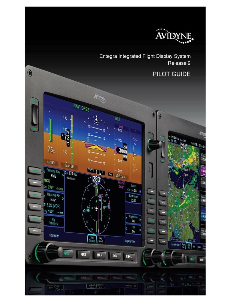
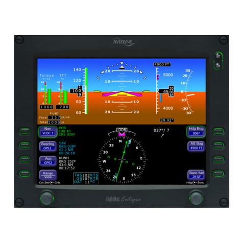
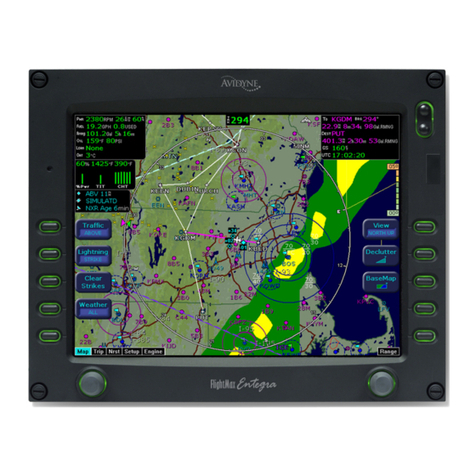
Avidyne Envision EXP5000 Manual

600-00157-000 Rev. 06
EXP5000
Primary Flight Display
Pilot’s Guide


600-00157-000 Rev. 06 -i- Entegra EXP5000 PFD
Document Revision History
This document is applicable to Software Part Numbers:
●530-00194-000 - Rel 7.0.X, Landscape PFD, No RVSM
●530-00200-000 - Rel 7.1 & later, Landscape PFD, With RVSM
●530-00200-001, and -002 - Rel 7.1 & later, Landscape PFD, No
RVSM
All materials are copyrighted including images that represent this software.
Copyright 2008 Avidyne Corporation. All rights reserved.
Date Revision Description
Oct. 12, 2006 00 Released per ECO-06-230
Oct. 18, 2006 01 Released per ECO-06-238
Aug. 8, 2007 02 Updated per ECO-07-254
Oct. 3, 2007 03 Updated per ECO-07-352
May 21, 2008 04 Updated per ECO-08-131
June 27, 2008 05 Updated per ECO-08-199
August 29, 2008 06 Updated per ECO-08-249

Entegra EXP5000 PFD -ii- 600-00157-000 Rev. 06
This page intentionally left blank.

600-00157-000 Rev. 06 -iii- Entegra EXP5000 PFD
Table of Contents
1Introduction.............................................................. 1
Notes and Warnings .................................................................... 1
2EXP5000 System Overview..................................... 3
EXP5000 Overview ..................................................................... 3
EXP5000 Upper Half Display ...................................................... 5
EXP5000 Lower Half Display .................................................... 11
EXP5000 Buttons and Knobs .................................................... 15
3Flying with the EXP5000........................................ 25
Introduction................................................................................ 25
Starting the EXP5000 ................................................................ 26
Startup Settings ......................................................................... 29
Setting Up the HSI..................................................................... 30
Using GPS/VHF Systems with the EXP5000 ............................ 32
Using the S-TEC 55X Autopilot with the EXP5000.................... 33
Using the S-TEC 1500 Autopilot with the EXP5000 .................. 39
Using the S-TEC IntelliFlight 2100 Autopilot with the EXP5000 42
Using Other Autopilots with the EXP5000 (PFD 530-00200-() soft-
ware only) .................................................................................. 46
Precision Flying with EXP5000.................................................. 50
Using the EXP5000 for Approaches.......................................... 52
4Invalid Sensors and Error Conditions ................. 57
Invalid Air Data .......................................................................... 58
Invalid Heading.......................................................................... 59
Crosscheck Monitor................................................................... 60
Warmstart Conditions ................................................................ 61
Recoverable Attitude ................................................................. 62
Invalid Attitude & Heading ......................................................... 63
Nav Source Crosscheck ............................................................ 64
Loss of Communication with Autopilot....................................... 65
5Using Dual PFDs.................................................... 67
Selecting the ADAHRS Source ................................................. 67
Synchronized and Non-synchronized Controls ......................... 69
Pilot Priority Switch.................................................................... 71
Dual PFD Error Conditions ........................................................ 72
Entegra EXP5000 PFD -iv- 600-00157-000 Rev. 06
Copyright....................................................................................75
AVIDYNE EXCLUSIVE LIMITED WARRANTY
and LIMITATIONS ON LIABILITY..............................................76
Software License .......................................................................79

600-00157-000 Rev. 06 -1- Entegra EXP5000 PFD
1 Introduction
This Pilot’s Guide provides information about the Envision EXP5000
PFD.
1.1 Notes and Warnings
Notes and warnings provide guidance for the use of the EXP5000.
Avidyne strongly suggests that you pay close attention to notes and
warnings for your own safety.
For example:
The instructions and warnings in this manual are not intended to
replace the instructions and warnings for other equipment on your
aircraft. It is critical that you as the pilot in command have a complete
understanding of the warnings, operating instructions, and limitations
for all equipment installed on your aircraft.
Note: Notes provide useful information about how to use the EXP5000
Primary Flight Display.
!
Warnings are prefaced with exclamation points and denote
information that can prevent serious injury or death on the
part of the user.
!
This manual assumes that the reader is an appropriately
licensed pilot. Avidyne strongly recommends that you use the
EXP5000 only under VFR conditions until you are very familiar
with the EXP5000.
If you have questions, please contact Avidyne at 800-284-
3963 (800-AVIDYNE) or +1-781-402-7400 before operating
with the Envision PFD under IFR conditions.
!
When using the EXP5000, be sure to cross-check the data
displayed against other data sources for accuracy including
other flight deck instruments and charts.

Notes and Warnings
Entegra EXP5000 PFD -2- 600-00157-000 Rev. 06
This page intentionally left blank.

600-00157-000 Rev. 06 -3- Entegra EXP5000 PFD
2 EXP5000 System Overview
This section contains the following information:
●EXP5000 Overview, page 3
●EXP5000 Upper Half Display, page 5
●EXP5000 Lower Half Display, page 11
●EXP5000 Buttons and Knobs, page 15
2.1 EXP5000 Overview
This section provides an overview of the Envision EXP5000.
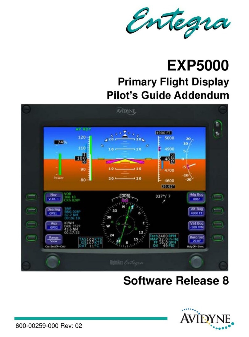
Figure 1. The Envision EXP5000 PFD
1) Brightness Control (BRT/DIM)—Allows you to adjust the
display brightness. Press the top button to brighten the display;
press the bottom button to dim it. The default brightness is 75%.
1
6
3 3
2
4
5
6

EXP5000 Overview
Entegra EXP5000 PFD -4- 600-00157-000 Rev. 06
2) Upper Half Display—The upper half of your EXP5000 displays
information about your aircraft attitude, autopilot status (when
equipped), navigation and more. This section includes the
following:
■Autopilot annunciations
■Attitude Direction Indicator (ADI)
■Airspeed Indicator (ASI)
■Altimeter
■Vertical Speed Indicator (VSI)
For information about the data displayed on the upper section of
the EXP5000, see Section 2.2, "EXP5000 Upper Half Display" on
page 5.
3) Buttons—Buttons allow you to display new information or
change the display. Button labels change to reflect the current
environment.
4) Lower Half Display—Displays the Horizontal Situation Indicator
(HSI) and other details about direction, windspeed, and flight
plans. The HSI can display a moving map to help you determine
your exact location. For more information, see Section
2.3, "EXP5000 Lower Half Display" on page 11.
5) Air Data Block—Contains air data information, including true
airspeed, ground speed, and outside air temperature (if an OAT
sensor is installed).
6) Left and Right Knobs—Knobs allow you to change the display
as indicated for the particular settings. The knob labels change to
indicate the active function.
■Left button and knob functions are described in Left Buttons
and Knob, on page 15.
■Right button and knob functions are described in Right
Buttons and Knob, on page 19.

EXP5000 System Overview
600-00157-000 Rev. 06 -5- Entegra EXP5000 PFD
2.2 EXP5000 Upper Half Display
Figure 2. EXP5000 Upper Half Display Symbols
Upper Half Display
The upper portion of the EXP5000 contains the following information:
1) Autopilot Annunciations—If your aircraft is equipped with an S-
TEC 55SR, 55X, or Intelliflight 2100 autopilot, autopilot
annunciations will appear across the top of the PFD. For
information on the annunciations, see the POH for your autopilot.
2) Airspeed Tape— Indicates the airspeed. The display range is
either:
■20 kts to 300 kts if using air data from the internal ADAHRS,
or
■40 kts to 500 kts if using air data from an external source.
The box at the top of the tape displays the current value of the
IAS Bug. The minor/major graduations are either 2 knots/10
5 4
2
3
6
8 7
9
10
13
11
14
12
1

EXP5000 Upper Half Display
Entegra EXP5000 PFD -6- 600-00157-000 Rev. 06
knots or 5 knots/20 knots as configured for your aircraft by the
avionics installer. Major graduations are labeled. Likewise, the
airspeed tape ranges are set for your aircraft by the avionics
installer. The airspeed tape has the following color bands:
3) Airspeed Window—Displays current indicated airspeed in knots.
Hash marks are displayed below 20 knots.
4) Skid/Slip Indicator—The black trapezoid is centered under the
roll pointer in coordinated flight. Full scale deflection is the width
of the trapezoid.
5) Bank Angle Indicator—The bank angle indicator is composed of
an inverted white triangle and an upright white triangular Roll
Pointer. The upright white triangle points to the current bank
angle. Graduations are at 0, 10, 20, 30, 45, and 60 degrees.
(Note that the 0 and 45 degree marks are inverted triangles).
6) Pitch Ladder—The pitch ladder is marked as follows:
■Every 2 1/2° within the range of ± 20°.
■Every 5° from +20° to +50° and -20° to -30°.
■10° graduations of the pitch ladder have bar ends that point
toward the horizon line.
Band
Color
Meaning
Red VNE or VMO (depending on aircraft type) up to top of the
airspeed tape.
Yellow VNO up to VNE (For VNE aircraft).
Green ■VS up to VNO (For VNE aircraft).
■VS up to VMO/MMO (For VMO aircraft).
White VSO up to VFE.
Red 20 kts up to VSO.
This red band is removed during takeoff.
(Twin engine only) One engine inoperative VSpeeds are
indicated by lines across the airspeed tape, as follows:
Blue ■VYSE —Best Climb Rate, One-Engine Inoperative
Red ■ VMCA—Minimum Controllable Airspeed, One-Engine Inop.

EXP5000 System Overview
600-00157-000 Rev. 06 -7- Entegra EXP5000 PFD
■±90° is represented by small circles.
■Large chevrons, described in Section 3.7 Precision Flying
with EXP5000, are only visible at excessive pitch angles and
point toward the horizon (above +50° and below -30°).
7) Aircraft Reference Symbol (ARS)—The ARS is fixed on the
display and provides a reference from which you can determine
aircraft attitude. The EXP5000 can be configured as one of two
different symbols:
■Yellow Delta—The Delta
ARS displays in aircraft
for which Flight Director
is supported. The yellow
outriggers are used with the ARS symbol to provide a
reference for wings level flight.
■Flying W—The flying W displays in
aircraft for which Flight Director is
not supported.
8) Flight Director Steering Command Bars—Displays the
accuracy of the pilot or autopilot tracking the autopilot
commands. The pilot or autopilot is to steer the airplane toward
the command bars until the ARS is tucked into the steering
command bars. For more information about Flight Director, see
the appropriate autopilot section:
■Using the S-TEC 55X Autopilot with the EXP5000, page 33.
■Using the S-TEC 1500 Autopilot with the EXP5000, page 39.
■Using the S-TEC IntelliFlight 2100 Autopilot with the
EXP5000, page 42.
■Using Other Autopilots with the EXP5000 (PFD 530-00200-()
software only), page 46.
9) Horizontal Deviation Indicator (HDI)—Displays when:
■The NAV source is VLOC.
Note: The Flight Director steering command bars display only when
Flight Director is enabled and available and the aircraft is configured to
display the Delta ARS symbol.

EXP5000 Upper Half Display
Entegra EXP5000 PFD -8- 600-00157-000 Rev. 06
■The localizer signal has been received.
Or (if used with Garmin 400W/500W navigator)
■The Nav source is GPS
■GPS horizontal deviation data has been received
The source of the HDI data is displayed immediately to the right
of the HDI (e.g., LOC, ILS or GPS). If the localizer signal is lost,
the HDI is replaced with a red X and the source letters turn red. If
GPS data is lost, the HDI is removed from the display.
To remove the HDI, change either the NAV source or the VOR/
LOC frequency.
10) Altitude Tape—Displays baro-corrected altitude. The display
range is either:
■-1,000 feet to 35,000 feet if using air data from the internal
ADAHRS, or
■-1,000 feet to 53,000 feet if using air data from an external
source.
The box at the top of the tape displays the current value of the Alt
Bug. In general, each minor graduation represents 20 feet and
each 100 foot graduation is labeled. For higher power aircraft,
each minor graduation represents 100 feet and each 500 foot
graduation is labeled. These settings are set by the installer and
may differ for your aircraft.
11) Altitude Window—Displays the current baro-corrected altitude.
12) Vertical Deviation Indicator (VDI)—Displays when:
■The Nav source is VLOC
■The ILS Glidescope signal has been received
■The VDI is not displayed for back course localizer
approaches
Or (if used with Garmin 400W/500W navigator)
■The Nav source is GPS
■GPS vertical deviation data has been received
To remove the VDI display, change either the NAV Source or the
localizer frequency.

EXP5000 System Overview
600-00157-000 Rev. 06 -9- Entegra EXP5000 PFD
13) Vertical Speed Indicator (VSI)—Displays the vertical speed in
Feet per Minute (fpm). The VSI generally shows ±2,000 fpm VSI
scale. Scale graduations display every 100 fpm between ±1,000
fpm. For higher power aircraft, the VSI shows ±3,000 fpm VSI
scale. Scale graduations display every 200 fpm between ±2,000
fpm. These settings are set by the installer and may differ for your
aircraft.
When vertical speed is above scale limits, a digital readout of the
current vertical speed is displayed on the appropriate end of the
VSI scale. The maximum displayed value of the digital readout is
either:
■±4,000 fpm if using air data from the internal ADAHRS, or
■±10,000 fpm if using air data from an external source.
14) Radar Altimeter Indicator—If your aircraft is equipped with a
radar altimeter, the Radar Altimeter indicator displays the current
altitude above ground level (up to 2500 ft. AGL) and the currently-
set decision height. Set the decision height for the radar altimeter
using the DH Alert button, described in Right Buttons and Knob,
on page 19.
EXP5000 Display Options
The following display options are set during installation:
Horizon Heading Reference Marks
Horizon Heading Reference Marks provide heading information on
the ADI. If Horizon Heading Reference Marks are installed on your
EXP5000, the marks and labels appear at each quadrant (N, E, S, W)
and mid-quadrant (NE, SE, SW, NW). The reference pointer for the
Heading Marks is the apex of the ARS.

EXP5000 Upper Half Display
Entegra EXP5000 PFD -10- 600-00157-000 Rev. 06
Labeled VSpeeds
Vx and VY labels are shown at the correct airspeeds for the Best
Angle of Climb speed (VX) and Best Rate of Climb speed (VY). VX
and VY are adjusted based on density altitude, as described in the
Airspeeds for Normal Operations section of your aircraft Pilot
Operating Handbook. Additionally, the VG label displays at the Best
Glide airspeed as listed in the Airspeeds for Emergency Operations
section of your aircraft POH.
At some altitudes, the characters marking the VSpeeds may overlap
and may be partially obscured.
Barometer Units
Barometer units can be displayed in In-Hg (Inches of mercury [default]), Mb
(Millibars), or hPa (Hectopascals). The average sea-level pressure is
29.92 in-hg or 1013.25 mb or hPa.
Aircraft Reference Symbol
Delta or Flying W. See the discussion of the Aircraft Reference
Symbol in Section 2.2, "EXP5000 Upper Half Display" on page 5 for
more information.
Note: If your aircraft POH lists Best Glide airspeeds for multiple gross
weights, VG is displayed as a range between the highest and lowest Best
Glide airspeed. Make sure you consult the POH for the correct Best Glide
airspeed for a particular gross weight.
Note: The VSpeeds for your aircraft were entered by the installer. There is
a small chance that, due to installer error, the VSpeed configuration will not
be valid. In this case, an Invalid VSpeeds message displays on the
Airspeed Tape. If this message displays, do not use the VSpeed information
on the PFD, and contact your installer as soon as practical.
Note: VX and VY speeds depend on settings made during installation.
Depending on your aircraft and installation settings, the VX and VY speeds
may not vary with density altitude.

EXP5000 System Overview
600-00157-000 Rev. 06 -11- Entegra EXP5000 PFD
2.3 EXP5000 Lower Half Display
The lower half of your EXP5000 provides navigation information, PFD
control softkeys, and air data.
The Horizontal Situation Indicator (HSI) displays as either a full 360°
circle or as a 120° arc (See Figure 4 on page 12). All lower-half
display features can appear in either the 360° or the 120° arc EHSI
views.
Figure 3. EXP5000 Lower Half Display Symbols
1) Magnetic Heading—A numeric indication of current aircraft
magnetic heading.
2) Rate of Turn Indicator—The tip of the blue rate of turn indicator
displays the current rate of turn. The indicator is marked for 1/2
and full standard rate of turn. An arrowhead indicates a value
beyond 1 1/2 standard rate. For more information, see the
Section , "Using Trend Indicators" on page 51.
1
23
5
6
4
12
7
11
8

EXP5000 Lower Half Display
Entegra EXP5000 PFD -12- 600-00157-000 Rev. 06
3) Wind Vector—Displays the current wind speed and wind
direction. The arrow indicates the direction of the wind relative to
the current aircraft heading.
➥After you turn, there will be a lag of several seconds in
updating current wind speed and direction.
The wind vector on the HSI is very useful in any phase of flight
where you need to take winds aloft into account. You can use a
combination of the wind vector and projected track line in
navigation tasks.
4) HSI—The Horizontal Situation Indicator (HSI) can be viewed as
either a full 360° circle or as a 120° arc. The EHSI views are
shown in Figure 4:
Figure 4. EHSI Views
5) Projected Track Line—The dashed gray projected track line
originates from the aircraft present position symbol and
terminates at the triangle along the outer edge of the compass
rose. It displays a projection of the current ground track of the
aircraft.
Note: Under very light wind conditions or when wind speed cannot be
calculated, wind data will be replaced by dashes.
360° View
120° Arc View
9
10
13
14

EXP5000 System Overview
600-00157-000 Rev. 06 -13- Entegra EXP5000 PFD
➥To take the guesswork out of determining proper crab angles
for wind corrections, align the projected track line with the
desired course.
6) Bearing Pointer—The blue dual-line bearing pointer is
associated with the Bearing source and displays the current
bearing to the Bearing waypoint (GPS 1 or GPS 2) or to the
station (VLOC 1 or VLOC 2). A bearing pointer does not display if
you tune the VLOC source to an ILS or LOC station.
7) Course Deviation Indicator (CDI)—The green single-line CDI
displays deviation from the set or desired course.
8) To-From Flag—The small green arrow indicates whether you are
heading to or from the current VOR or GPS waypoint. If you are
heading to the VOR, the arrow points the direction you are flying.
If from, the arrow points towards your most recent VOR or
waypoint.
9) HSI Moving Map—Displays up to a maximum of 15 waypoints
and labels from the active flight plan. The active leg of the flight
plan is depicted in magenta, and all other legs of the flight plan
are depicted in white. The moving map will also display waypoints
and labels of an approach and hold.
10) HSI Map Range—When the moving map is selected for display
on the HSI via the View knob, the outer and inner rings of the
compass rose are labeled with range in nautical miles. Outer ring
ranges are 2, 5, 10, 20, 50, 100, and 200 NM.
11) Compass Rose—In both the 360° view and 120° arc view, the
minor graduation marks represent 5 degrees, major graduation
marks represent 10 degrees, with every 30 degrees labeled. The
outer edge of the compass rose is marked with reference marks.
12) Air Data Block—This data block is configurable and may
contain:
■True Airspeed (TAS) in knots
■Ground Speed (GS) in knots
■OAT (Outside Air Temperature) in degrees F or C as
configured
Note: In dual-PFD equipped aircraft, differences between the two wind
vectors during light winds are normal.

EXP5000 Lower Half Display
Entegra EXP5000 PFD -14- 600-00157-000 Rev. 06
13) MSG Annunciator—Illuminates when there is a message on the
GPS navigator.
14) WPT Annunciator—Illuminates when the GPS navigator detects
the approaching of a waypoint.
Table of contents
Other Avidyne Avionic Display manuals

Avidyne
Avidyne IFD550 User manual

Avidyne
Avidyne Entegra EXP5000 Installation and operating instructions

Avidyne
Avidyne Entegra EX5000 User manual

Avidyne
Avidyne FlightMax EX5000 Manual

Avidyne
Avidyne Entegra Manual

Avidyne
Avidyne IFD5 Series User manual

Avidyne
Avidyne Entegra EXP5000 Manual

Avidyne
Avidyne IFD550 Manual

Avidyne
Avidyne IFD440 User manual

Avidyne
Avidyne IFD440 Manual