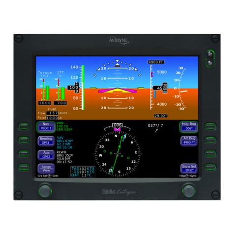
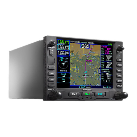
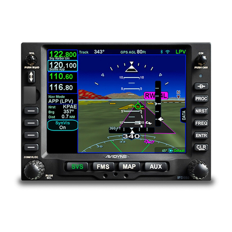
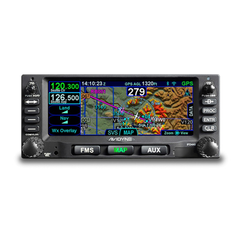
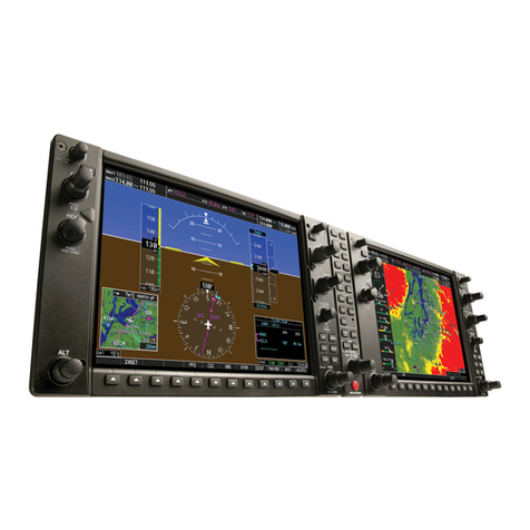
Avidyne IFD550 Manual


Revision History
Revision
Date of Release
Reason for Release
00
April 2015
Initial Release of document that
coincided with Software
Release 10.1.0.0
01
July 2015
Optimizations for black and
white printing
02
November 2015
Corrected several errors and
added some additional
descriptions
03
December 2016
Update to accompany Software
Release 10.2.0.0
04
March 2017
Formatting changes to improve
printed copies
05
February 2018
Update to accompany Software
Release 10.2.1.0
06
March 2018
Added network connection
description 10.2.1.0
07
April 2019
Update to accompany Software
Release 10.2.3.1. Combined
all IFD500 series products into
one document
08
September 2021
Update to accompany Software
Release 10.3.0.2

IFD500 Series Pilot Guide
Table of Contents 1
TABLE OF CONTENTS
1System Overview...............................................................1-1
INTENDED FUNCTION.......................................................1-2
IFD540 .............................................................................1-2
IFD510 .............................................................................1-3
IFD550 .............................................................................1-4
IFD545 .............................................................................1-5
FUNCTIONAL OVERVIEW .................................................1-8
BASIC CONCEPTS...........................................................1-10
Page Keys......................................................................1-10
Line Select Keys............................................................1-10
Right Knob Labeling.......................................................1-11
Color Philosophy............................................................1-11
GENERAL IFD OPERATIONS ..........................................1-13
IFD540 & IFD550 Bezel Layout.....................................1-13
IFD510 & IFD545 Bezel Layout.....................................1-13
Power Control ................................................................1-16
Brightness Controls........................................................1-17
Start-Up Sequence ........................................................1-18
Database Currency States.............................................1-21
Page Layout and Formats..............................................1-23
Com-Nav †.....................................................................1-25
Frequency List †............................................................1-34
Transponder Control and Display..................................1-36
Direct-To Operations......................................................1-39
Function Keys ................................................................1-41
Touch Screen.................................................................1-43
Operations with Wireless Devices .................................1-47
Dual IFD Operations ......................................................1-52
SBAS vs Non-SBAS Operations....................................1-56
Interaction With External Devices..................................1-57
Before Takeoff Techniques............................................1-58
2SVS Subsystem ‡...............................................................2-1
SYNTHETIC VISION PAGE ................................................2-2
Synthetic Vision With Datablocks ....................................2-6
Synthetic Vision Obstacles ..............................................2-7
Synthetic Vision Terrain Awareness..............................2-11
SVS Forward Looking Terrain avoidance (FLTA)..........2-12
Flying Approaches with Synthetic Vision.......................2-14
SVS Page Variations .....................................................2-21
Operational Limits of the ARS .......................................2-23

IFD500 Series Pilot Guide
2 Table of Contents
3FMS Subsystem .................................................................3-1
FPL (FLIGHT PLAN) TAB....................................................3-2
FMS Basic Concepts .......................................................3-2
Creating a New Flight Plan..............................................3-9
Previewing Flight Plans..................................................3-10
Selecting a Departure ....................................................3-11
Inserting A Waypoint......................................................3-15
Inserting an Airway ........................................................3-15
Deleting A Waypoint ......................................................3-17
Editing A Waypoint.........................................................3-18
Adding Altitude Constraints............................................3-18
Direct-To........................................................................3-19
Entering And Intercepting A Radial................................3-23
Deleting A Flight Plan ....................................................3-24
Creating A Holding Pattern............................................3-25
Circular Orbits................................................................3-26
Deleting A Holding Pattern.............................................3-28
Editing A Holding Pattern...............................................3-28
Activating a Flight Plan ..................................................3-29
Flight Plan Sequencing..................................................3-29
Lateral Offsets................................................................3-30
Flight Plan Discontinuities..............................................3-31
Enroute Descents ..........................................................3-33
Entering An Arrival and Approach .................................3-36
Visual Approaches.........................................................3-40
Activating A Leg.............................................................3-43
Use of the Map FPL Split Page .....................................3-44
Chart Access..................................................................3-45
INFO TAB ..........................................................................3-47
ROUTE TAB ......................................................................3-51
Creating A New Route...................................................3-52
Editing a Route ..............................................................3-52
Naming A Route.............................................................3-52
Copying A Route............................................................3-53
Inverting A Route ...........................................................3-55
Activating A Route .........................................................3-56
Deleting A Route............................................................3-57
WPT (USER WAYPOINTS) TAB.......................................3-58
Creating A User Waypoint .............................................3-58
Naming A User Waypoint...............................................3-59
Deleting A User Waypoint..............................................3-59
Designating A User Waypoint As An Airfield.................3-59
NRST (NEAREST) TAB.....................................................3-62

IFD500 Series Pilot Guide
Table of Contents 3
4Map Subsystem..................................................................4-1
MAP TAB .............................................................................4-2
Map Controls....................................................................4-2
Other Map Features.........................................................4-6
Fuel Range Rings ..........................................................4-10
Decluttering The Map.....................................................4-12
Map Panning..................................................................4-13
Graphical Flight Planning (“Rubber Banding”)...............4-14
Altitude Constraints On Map..........................................4-16
Map Information Pop-Up Boxes.....................................4-16
Datalink Weather Overlays And Operations..................4-18
Datalink Radar ...............................................................4-21
Weather Overlays On Map ............................................4-25
TFR................................................................................4-28
Indications Of Data Age.................................................4-29
Weather Radar Selection For Map Overlay...................4-30
Traffic Display ................................................................4-32
Traffic Sensor Control....................................................4-40
Terrain Awareness.........................................................4-42
Forward Looking Terrain Avoidance (FLTA)..................4-45
Altitude Callout...............................................................4-47
TAWS.................................................................................4-47
Premature Descent Alert (PDA).....................................4-50
Excessive Descent Rate (EDR).....................................4-51
Negative Climb Rate / Altitude Lost After Takeoff .........4-52
TAWS Inhibit Control .....................................................4-53
TAWS Self-Test.............................................................4-53
Degraded Or No TAWS Conditions...............................4-53
HELICOPTER TAWS (HTAWS)........................................4-54
SYNTHETIC VISION (SVS) / TAWS TAB.........................4-57
Flight Plan Display.........................................................4-59
TAWS Control................................................................4-63
Self-Test.........................................................................4-64
CHART TAB.......................................................................4-65
Directory List..................................................................4-65
European Visual Approach, Landing And Area Charts .4-66
Chart Extent Box............................................................4-67
Hot Links To Charts .......................................................4-68
Chart Views....................................................................4-69
Taxi Charts/Airport Diagrams.........................................4-70
Lighting...........................................................................4-71
Watermarking / Expired Data.........................................4-72
Disabling Charts.............................................................4-72

IFD500 Series Pilot Guide
4 Table of Contents
Updating Charts.............................................................4-72
RADAR TAB ......................................................................4-73
VIDEO TAB........................................................................4-80
5Aux Subsystem..................................................................5-1
AUDIO TAB..........................................................................5-2
Volume Control ................................................................5-2
Satellite Radio Tuning......................................................5-4
Com Presets †.................................................................5-6
UTIL (UTILITIES) TAB.........................................................5-8
Timers..............................................................................5-8
Calculators.....................................................................5-12
Electronic Checklist........................................................5-17
SETUP TAB.......................................................................5-22
Category Structure.........................................................5-22
Item structure.................................................................5-23
Item editing ....................................................................5-23
Alerts Category ..............................................................5-26
Charts Category.............................................................5-29
Connectivity Category....................................................5-31
Datablocks Category......................................................5-39
Display Category............................................................5-54
FMS Category................................................................5-57
Map Category ................................................................5-62
Radio Category † ...........................................................5-68
SVS Category‡ ..............................................................5-69
Terrain Category............................................................5-70
Time Category ...............................................................5-72
Transponder Category...................................................5-74
Units Category ...............................................................5-75
User profile Category.....................................................5-78
Presets...........................................................................5-79
SYS (SYSTEM) TAB..........................................................5-86
Fuel Management..........................................................5-86
System Status................................................................5-88
ALERT TAB .....................................................................5-100
6Navigation...........................................................................6-1
NAV SOURCE KNOB/BUTTON..........................................6-5
OBS MODE..........................................................................6-9
VOR COURSE DEPICTION †...........................................6-13
ARMED VS ENGAGED/ACTIVE INDICATIONS...............6-14
FMS HOOKS .....................................................................6-15
COURSE CHANGES AND HOLDS...................................6-18

IFD500 Series Pilot Guide
Table of Contents 5
AUTO VLOC TUNING † ....................................................6-19
TRANSITION ALTITUDES/LEVELS..................................6-20
NAVIGATION MODE/CDI SCALE CHANGING ................6-22
APPROACH PROCEDURES ............................................6-23
Automatic mode switching †..........................................6-24
Precision Approaches....................................................6-25
Non-Precision Approaches............................................6-26
Back Course Approaches †...........................................6-26
SBAS Approaches .........................................................6-26
Visual Approaches.........................................................6-30
MISSED APPROACH........................................................6-32
RETRY APPROACH..........................................................6-35
ENROUTE VERTICAL NAVIGATION (VNAV)..................6-36
Allowing Enroute VNAV.................................................6-37
Defining the enroute VNAV altitude target.....................6-37
Defining the descent path..............................................6-38
Vertical Direct-To...........................................................6-39
Enroute VNAV Indications .............................................6-40
RECOMMENDED ICAO EQUIPMENT CODES................6-42
7General................................................................................7-1
CREW ALERTING SYSTEM (CAS) / ALERTS...................7-2
Master Caution Lamp.......................................................7-2
Alert Message Bar ...........................................................7-3
SELF TEST OUTPUT........................................................7-30
SYSTEM FAILURES..........................................................7-31
Power Distribution..........................................................7-31
Loss Of IFD....................................................................7-31
Loss Of Display..............................................................7-32
Loss Of Bezel Controls..................................................7-33
Loss Of Touchscreen Control........................................7-33
Loss Of GPS (Dead Reckoning)....................................7-34
Other Anomalies ............................................................7-35
SUBSCRIPTIONS..............................................................7-36
NIGHT OPERATIONS.......................................................7-37
IFD DISPLAY BRIGHTNESS ........................................7-37
IFD Bezel Brightness .....................................................7-37
Charts Lighting Scheme.................................................7-37
Display Of Terrain On Map............................................7-37
HIGH TEMPERATURE OPERATIONS.............................7-37
COLD TEMPERATURE OPERATIONS............................7-39
LOW POWER OPERATIONS ...........................................7-40
HIGH POWER OPERATIONS...........................................7-41
USE OF GLOVES..............................................................7-42

IFD500 Series Pilot Guide
6 Table of Contents
CHARGING FROM THE USB ...........................................7-44
INTEGRATION WITH THE IFD100 MOBILE APP............7-45
DEMO MODE ....................................................................7-46
DATA TRANSFER TO/FROM EXTERNAL DEVICES......7-49
REGULATORY COMPLIANCE STATEMENTS................7-53
Radio Regulatory Compliance Statements†..................7-53
Déclaration(s) de conformité réglementaire†.................7-54
FIS-B Weather ...............................................................7-55
MAINTENANCE MODE.....................................................7-56
Starting Maintenance Mode at power up.......................7-56
Starting Maintenance Mode from Flight Mode...............7-56
Exiting Maintenance Mode.............................................7-59
DATABASE UPDATES......................................................7-60
SOFTWARE UPDATES ....................................................7-67
DATALOGS DOWNLOAD.................................................7-68
USER DATA BACKUP/RESTORATION PROCEDURE...7-73
Saving User Data...........................................................7-73
Reloading Previously Stored User Data ........................7-74
TRANSFERRING USER WAYPOINTS.............................7-75
Uploading User Waypoints ............................................7-76
Downloading User Waypoints........................................7-78
PAIRING A BLUETOOTH®KEYBOARD...........................7-79
Verification of successful pairing ...................................7-84
CLEANING THE DISPLAY................................................7-86
SLIDE-IN REPLACEMENT DETAILS................................7-87

IFD500 Series Pilot Guide
System Overview 1-1
1 System Overview
All images contained in this manual are for reference use only,
and are subject to change.
Avidyne strongly recommends that pilots use the IFD system only
under VFR conditions until completely familiar with its operation
and use.
Boxed areas marked as NOTE within this manual identify certain
situations or areas of operation having heightened safety
implications. While it is important for the operator to be familiar
with all of the information in the manual, it is essential to the safe
use of the IFD that pilots give careful attention to the material
contained within these NOTEs.
In order to avoid a diversion of attention from the task of safely
taxiing, pilots should avoid performing the described cockpit tasks
while the aircraft is in motion on the ground. It remains the pilot’s
duty to monitor the IFD for proper function upon activation and
during use.
Internal data logs and the storage devices that record and store
data are property of Avidyne.

IFD500 Series Pilot Guide
1-2 System Overview
INTENDED FUNCTION
This manual describes the operation of the Avidyne IFD5xx series
of equipment. Not all capabilities described herein are applicable
to every model in the series. The IFD540 is the basis for
capabilities described in the manual. Differences from the
IFD540 are specifically identified throughout the manual.
IFD540
The Avidyne IFD540 is a GPS, VHF Communication, and VHF
Navigation transceiver whose primary function is to conduct VHF
communication and navigation, and to serve as the primary
navigation system for VFR and IFR VHF and GPS navigation and
instrument flying, provided it is connected to an external
navigation source selection annunciator and a CDI/HSI indicator
that is installed in the required field of view.
IFD540 Integrated Flight Display
Supplemental IFD functions include a moving-map, flight
management system (FMS), electronic charts, checklists, and a
number of timer and calculator types of utilities. Optional IFD
functions include control and display of remote transponders,

IFD500 Series Pilot Guide
System Overview 1-3
weather radar, and external video. The system includes terrain
alerting as well as an option for TAWS (or HTAWS).
IFD510
The Avidyne IFD510 differs from the IFD540 in that there is no
internal VHF transceiver. Its primary function is to conduct GPS
navigation, provided it is connected to an external navigation
source selection annunciator and CDI/HSI indicator that are
installed in the required field of view. The IFD510 cannot be used
to execute terminal area procedures that rely on VHF navigation.
The IFD510 bezel differs physically from the IFD540 in that the
radio controls along the left side of the bezel are absent, the
navigation source selection knob is replaced by an OBS button,
and the volume knob is replaced by a single-function power on/off
button.
IFD510 Integrated Flight Display
DOCUMENTATION CONVENTION
Throughout this document, capabilities that are
not applicable to the IFD510 are identified using
a † symbol.

IFD500 Series Pilot Guide
1-4 System Overview
IFD550
The Avidyne IFD550 is a GPS, VHF Communication, and VHF
Navigation transceiver whose primary function is to conduct VHF
communication and navigation, and to serve as the primary
navigation system for VFR and IFR VHF and GPS navigation and
instrument flying, provided it is connected to an external
navigation source selection annunciator and a CDI/HSI indicator
that is installed in the required field of view.
IFD550 Integrated Flight Display
The IFD550 also provides a synthetic terrain/vision image to
enhance the pilot’s awareness of their spatial position relative to
the terrain, obstacles and known traffic. Pitch, roll, and skid/slip
indicators also aid in attitude awareness. If the system is
receiving a heading input, then heading and rate of turn will be
displayed for additional aircraft state awareness. In degraded
conditions, the synthetic vision view will be replaced with a
traditional blue over brown attitude indication. The attitude
sensing and depiction of the IFD550 provides a non-required
secondary indicator in addition to the required attitude
instruments installed in the aircraft.

IFD500 Series Pilot Guide
System Overview 1-5
DOCUMENTATION CONVENTION
Throughout this document, capabilities that are
applicable only to the IFD550 or IFD545 are
identified using a ‡ symbol.
NOTE
Synthetic Vision Terrain Awareness
The synthetic vision display may not match the
terrain perfectly, but the display provides a
reasonable representation of the terrain in a manner
that does not misrepresent the threat posed by the
terrain. While possibly resolution or field-of-view
limited, the display still adequately portrays the
terrain for terrain awareness.
NOTE
Synthetic Vision is Not for Terrain Avoidance
The synthetic vision display may not be used as the
principal means for terrain avoidance. Synthetic
Vision may not provide the depth/distance cues
necessary for terrain avoidance and should always
be used in conjunction with other flight and
navigation information for terrain avoidance.
IFD545
The Avidyne IFD545 differs from the IFD550 in that there is no
internal VHF transceiver. Its primary function is to conduct GPS
navigation, provided it is connected to an external navigation
source selection annunciator and a CDI/HSI indicator that is
installed in the required field of view. The IFD545 cannot be used
to execute terminal area procedures that rely on VHF navigation.
The IFD545 bezel differs physically from the IFD550 in that the
radio controls along the left side of the bezel are absent, the
navigation source selection knob is replaced by an OBS button,

IFD500 Series Pilot Guide
1-6 System Overview
and the volume knob is replaced by a single-function on/off
button.
IFD545 Integrated Flight Display
The IFD545 also provides a synthetic terrain image to enhance
the pilot’s awareness of their spatial position relative to the
terrain, obstacles and known traffic. Pitch, roll, and skid/slip
indicators also aid in attitude awareness. If the system is
receiving a heading input, then heading and rate of turn will be
displayed for additional aircraft state awareness. In degraded
conditions, the synthetic vision view will be replaced with a
traditional blue over brown attitude indication. The attitude
sensing and depiction of the IFD545 provides a non-required
secondary indicator in addition to the required attitude
instruments installed in the aircraft.

IFD500 Series Pilot Guide
System Overview 1-7
DOCUMENTATION CONVENTION
Throughout this document, capabilities that are
not applicable to the IFD545 are identified using
a † symbol. Also, capabilities that are applicable
only to the IFD550 or IFD545 are identified using
a ‡ symbol.

IFD500 Series Pilot Guide
1-8 System Overview
FUNCTIONAL OVERVIEW
The Avidyne Integrated Flight Display (IFD) system supports the
following functions:
Flight Management System (FMS)
SBAS and non-SBAS GPS Navigation
VHF Communication and Navigation (16W and 10W
variants) †
Synthetic Vision (SVS) ‡
Attitude display ‡
Moving map, including synthetic vision view
Terrain Awareness
Forward Looking Terrain Alerting (FLTA)
Terrain Awareness Warning System (TAWS/HTAWS)
[optional]
Display of datalink weather
ADS-B position and display
Lightning sensor display
Onboard weather radar display [optional]
Video input [optional]
Traffic display
Electronic approach plates
Electronic checklists
Data logging
Crew Alerting System (CAS)
Utilities (e.g. Schedulers, Timers, Calculators)
Multi-touch touch screen control
Multiple IFD operations
Remote transponder control and display
WiFi and Bluetooth®communication
The system has been designed for single-pilot IFR operation and
features a Page and Tab user interface.

IFD500 Series Pilot Guide
System Overview 1-9
Most functions revolve around the page keys that appear across
the bottom edge of the bezel. Each of the pages has associated
tabs, which contain related data, often in different views. These
functions and tabs are covered in detail throughout this reference
manual.
NOTE
Global SBAS Support
Wide area/regional satellite based augmentation
system (SBAS) support provided by the IFD include
WAAS (Continental US, Alaska, Canada and most
of Central America), EGNOS (most of Europe and
North Africa), MSAS (Japan) and GAGNAN (India).
These are regional augmentations of the GPS
satellite constellation and should not be interpreted
as meaning the IFD is compatible with other GNSS
constellation systems such as Galileo (Europe),
GLONASS (Russia), or Compass (China).
NOTE
The TAWS and HTAWS functions provided by the
IFD are compliant with TSO-C151d and TSO-C194,
respectively.

IFD500 Series Pilot Guide
1-10 System Overview
BASIC CONCEPTS
PAGE KEYS
The buttons along the bottom of the IFD bezel are called “page
keys”. Each key is labeled by function:
SVS (Synthetic Vision System) ‡
FMS (Flight Management System)
MAP (Moving Map)
AUX (System Pages)
Each page has a number of associated tabs. Each page key has
a left and right rocker nature to it. Select the page of interest by
pressing either side of the page key and navigate through the
available tabs by pressing the left or right side, in the direction of
the desired tab.
Page Keys (IFD540 and IFD510)
Page Keys (IFD550 and IFD545)
LINE SELECT KEYS
Line Select Keys (LSK), are the buttons found along the left side
of the bezel. These are different from page keys in that they are
labeled on the screen, just inside the bezel adjacent to the
physical button, indicating the function of the LSK. An LSK can
either represent an action or a state.
A State LSK is identified by a title on the first row, shown in blue-
green, and the current state on the second row shown in white.
The title reflects the system function or setting to be affected, and

IFD500 Series Pilot Guide
System Overview 1-11
the state shows the current state of that setting. Pressing the
LSK or touching the label will change to the next state.
An Action LSK is identified by a phrase shown in blue-green.
The phrase is usually in verb-subject form, but there are
exceptions when the verb is omitted (e.g. "Timers"). Pressing the
LSK or touching the label will cause the system to perform the
specified action.
LSK Types
RIGHT KNOB LABELING
The bottom right dual-concentric knob on the IFD is context-
sensitive. Displayed in the lower right corner of the display, the
knob label indicates the function of the knobs and the knob button
on the left and right side, respectively. The symbol used to
represent the knob button is a ring with a center dot.
Right Knob Label Scheme
In the example above, the outer knob scrolls through a list in a
coarse manner and the inner knob scrolls through the same list
stopping at each minor field along the way. Pushing the knob
generates a drop-down menu.
COLOR PHILOSOPHY
There are a few generalities with the use of color that are
consistent across the IFD as described in the table below:

IFD500 Series Pilot Guide
1-12 System Overview
IFD Feature/Function
Color
Page keys
Green - Active
White - Available but not
currently active
Note: AUX can also be Red,
Yellow, or Cyan if there is an
active alert as described later
in this manual
FMS “Fly To” Data (e.g. active
leg of flight plan, To Waypoint
datablock)
Magenta
Active Navigation Data (e.g.
Active Com frequency, Active
Navigation frequency, Active
Navigation Source mode)
Green
Line Select Key Labels
Light Blue-Green
Line Select Key States
White
Other manuals for IFD550
2
This manual suits for next models
3
Table of contents
Other Avidyne Avionic Display manuals

Avidyne
Avidyne FlightMax EX5000 Manual

Avidyne
Avidyne Entegra EXP5000 Installation and operating instructions

Avidyne
Avidyne Entegra EX5000 User manual

Avidyne
Avidyne Entegra Manual

Avidyne
Avidyne Envision EX5000 Manual

Avidyne
Avidyne Envision EXP5000 Manual

Avidyne
Avidyne Entegra Manual

Avidyne
Avidyne IFD550 User manual

Avidyne
Avidyne IFD440 Manual

Avidyne
Avidyne 700-00182 Series Service manual