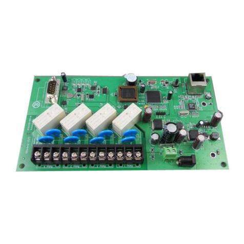
Aviosys IP Power 9223K-A User manual

- 1-
Ref#9223K05260001
IP Power 9223K-A
User Manual
Release Date: 12/7/2011
Manual Version: 1.0
Firmware:

- 2-
Ref#9223K05260001
Warning: Any changes made to this equipment without permission may cause
damages to the device!
IMPORTANT NOTICE
1. IP Power 9223K-A was designed to be used with a protective covering, the user is responsible
for any damages caused from misuse, or use under inappropriate conditions.
2. Please use the power adapter provided by the dealer, the manufacturer is not responsible for
any damage caused from using power adapters not.
3. Do not shake the IP Power 9223K-A in any fashion
4. Please contact the dealer If IP Power 9223K-A is not working properly.
Copyright © 2010 All rights reserved. No part of this publication may be reproduced, stored in a
retrieval system, or transmitted in any form or by any means, electronic, mechanical,
photocopying, recording or otherwise, without the prior written consent of us.
All trademarks and products mentioned in this document are the properties of us.

- 3-
Ref#9223K05260001
Table of Content
2T1.) WELCOME2T ........................................................................................................................4
2TINTRODUCTION2T .........................................................................................................................4
2TMINIMUM SYSTEM REQUIREMENTS2T ...............................................................................................5
2T2.) PRODUCT OVERVIEW2T .......................................................................................................6
2TFEATURES2T ................................................................................................................................6
2TSPECIFICATION2T ..........................................................................................................................6
2TPACKAGE CONTENTS2T ..................................................................................................................7
2T3.) INTERFACE DESCRIPTION2T ..................................................................................................8
2THARDWARE INTERFACE2T ...............................................................................................................8
2T4.) HARDWARE SETUP2T ...........................................................................................................9
2TSETTING UP THE DEVICE2T ..............................................................................................................9
2TNORMALLY CLOSED CIRCUIT (NC) OR NORMALLY OPEN CIRCUIT (NO)2T ........................................................ 9
2TCONNECTING DEVICES TO THE 9223K-A2T ............................................................................................... 10
2TINTERNET ACCESSIBLE SETUP2T ......................................................................................................11
2T5.) IP EDIT SEARCH TOOL2T .....................................................................................................11
2TUSING IP EDIT2T ........................................................................................................................11
2TIP SERVICE2T .............................................................................................................................12
2T6.) WEB INTERFACE2T .............................................................................................................14
2TCONNECTING TO THE 9223K-A2T ..................................................................................................14
2TGPIO CONFIGURATION2T .............................................................................................................14
2TSET I/O2T ........................................................................................................................................... 14
2TDEFINE I/O NAME2T............................................................................................................................. 15
2TSYSTEM SETTINGS2T....................................................................................................................17
2TSYSTEM CONFIGURATION2T ................................................................................................................... 17
2TADVANCE SETUP2T ............................................................................................................................... 17
2TDDNS2T ............................................................................................................................................. 18

- 4-
Ref#9223K05260001
2TE-MAIL2T ............................................................................................................................................ 18
2TCHANGE PASSWORD2T .......................................................................................................................... 19
2TPOWER SCHEDULE2T ............................................................................................................................. 19
2TNETWORK WAKE UP2T .......................................................................................................................... 21
2TLOGOUT2T .......................................................................................................................................... 21
2TINTERNAL TIME2T .......................................................................................................................21
2TDATE/TIME SETTINGS2T ........................................................................................................................ 21
2T7.) CONTROLLING THE DEVICE2T .............................................................................................21
2TCGI HTTP COMMANDS2T ............................................................................................................21
2THELP COMMAND2T .............................................................................................................................. 22
2TSET POWER COMMAND2T ..................................................................................................................... 22
2TREAD POWER COMMAND2T ................................................................................................................... 22
2TRS232 CONTROL2T ....................................................................................................................23
2T8.) FREQUENTLY ASKED QUESTIONS (F.A.Q)2T .........................................................................23

- 5-
Ref#9223K05260001
1.) Welcome
Introduction
The 9223K-A is an industrial grade 4 port bare board relay perfect to power management through an
Ethernet connection. This device can easily integrate with other devices and allow power control with your
integrated system. With the 9223K-A robust design and high quality components it provides an added
incentive to other devices or can be used independently. The 9223K-A brings an economical solution to a
professional industry.

- 6-
Ref#9223K05260001
Minimum System Requirements
CPU Minimum Requirements
Intel(R), Pentium(R), DUAL Core (D),CPU 3.0GHz or equivalent
Operating Systems: WINDOWS Operating Systems (IE5.0+SPI & Firefox)
512 MB system memory or above
10/100 Ethernet switch/hub
Sound Card: DirectX 9.0c compatible sound card
Ethernet network port/card
Network cable
Internet (For remote access) or Ethernet Network (Internal Network use) with some type of Internet
connection, (i.e. ADSL, Cable, Dial up or any other forms of Internet service)
Software
Windows XP Service Pack 2 or above.
Resolution of screen setting: 800x600 or higher

- 7-
Ref#9223K05260001
2.) Product Overview
Features
1. Inrush Current relay design for extra protection.
2. Designed to control T5 fluorescent lighting.
3. Embedded web server – No PC needed to connect.
4. Industrial 4 Port Relay design network controller
5. Accessible with popular web browsers - IE, Google Chrome, Netscape & Firefox.
6. Each relay can support current up to 8Amp
7. Power surge protection design to protect against high voltage power surge.
8. Designed to meet high voltage and current safety standard design and regulation.
9. Reliability and testing certification MBTF +200,000 hrs+
10. RS232 Control by inquiry (OEM projects) for system integration.
11. PCB standard safety design of 5mm soldering distance
12. Network protocols supported: Http, DDNS, DHCP, Virtual and Dynamic IP.
13. SNMP for trap – send message to manage server.
14. SDK (VB & VC) for own software development.
Specification
Power Input:
AC Adaptor Input: 100-240V~0.3A MAX 10-20VA, 50-60Hz
Relay Specs: AC 250V / DC 30V
Weight:
192.6 grams without packaging.
Dimensions (L x H):
16cm x 13cm
Casing:
Bare board
Relay Specification:
Normal Close(NC)
Regular Use: Max. 4A / port
T5 fluorescent light control: 120Watt
Normal Open(NO)
Regular Use: Max. 8A / port
T5 fluorescent light control: 240Watt

- 8-
Ref#9223K05260001
Package Contents
Package
Contents
1.) 9223K-
A Unit x 1
2.) 9223K-
A
Installation
CD
CD will provide manual, software, and documentation on the 9223K-A
3.) AC
Adaptor
(One AC adaptor will be included and will correspond to the countries power standards)
Specs:
Input: 100-250Vac /47-63Hz, 1A
Output: 12Vdc/1A

- 9-
Ref#9223K05260001
3.) Interface Description
Hardware Interface
DC 12V Power Input:
Plug in the Power Adapter to the DC 12V
Power Control
4 Normally Closed (NC) & Normally Open (NO)
Power ports
RJ45 Ethernet:
Plug in the RJ45 Ethernet cable to the Ethernet port
RS232 Port:
For System Integration and Control
RESET
Hold down for two seconds until you hear a long
beep revert to manufacturer default.

- 10-
Ref#9223K05260001
4.) Hardware Setup
*Before setup the device make sure of the following:
1.) Make sure that all the package contents are all included if anything is missing please contact the
store or your distributor.
2.) Make sure the power adaptor is the correct specification.
3.) Make sure that all the cables are working correctly
Setting up the Device
Warning: This part of the procedure can be very dangerous. Please follow instructions carefully or consult
an electrician or someone who is experienced in the field to assist in the part of the procedure. Aviosys is
not responsible for any damages to the device or harm caused by from misuse, incorrect installation, and (or)
dangerous environment.
Normally Closed Circuit (NC) or Normally Open Circuit (NO)
The 9223K-A consists of a total of four relays. Each of the relays on the board has the option to pick whether
this circuit will be normally closed (NC) or normally open (NO).
Each relay can support a voltage up to 240VAC / 30 Vdc. & a current of up to:
Normal Close(NC)
Regular Use: Max. 4A / port
T5 fluorescent light control: 120Watt
Normal Open(NO)
Regular Use: Max. 8A / port
T5 fluorescent light control: 240Watt

- 11-
Ref#9223K05260001
Note:
Please remember that you use normally open or normally closed the output control will either create a open
circuit or a closed circuit.
Device Status
Control Status
Circuit
Normally Closed
On
Open
Normally Open
On
Closed
Connecting devices to the 9223K-A
Warning: This part of the procedure can be very dangerous. Please follow instructions carefully or consult
an electrician or someone who is experienced in the field to assist in the part of the procedure. Aviosys is
not responsible for any damages to the device or harm caused by from misuse, incorrect installation, and (or)
dangerous environment.
When connecting the device it is crucial not to have the power of the 9223K-A connected.
1.) First connect the cables to the 9223K-A. Make sure that you have stripped enough of the cable so
that the contacts can fit into the 9223K-A.
a. During this part you will need to decide whether each relay will start normally open or
normally closed. Once you have decided, carefully unscrew the inputs and place the
contacts into the input area and screw on tightly.
2.) Plug in the network cable RJ45 into the 9223K-A
3.) After correctly installing steps 1 and 2 for the very last step plug in the power cable that came with
9223K-A.

- 12-
Ref#9223K05260001
Internet Accessible Setup
To be able to access the 9223K-A through the internet, the user must port forward on the router. Since each
router is different, please refer to the routers manual on how to port forward the device. Once the device has
been successfully port forwarded the use can connect the device from the internet.
For example
If the 9223K-A
IP Address: 192.168.100.200
Port: 9223
On the router you will need to port forward the IP Address 192.168.100.200 on Port 9223.
5.) IP Edit Search Tool
Using IP Edit
IPEdit is a search tool designed to setup and access the IP Power 9223K-A.
IP Service is an additional feature which searches for the device easily without having to remember long
complicated IP addresses. Instead, this technology allows the user find his or her device through the internet
just by device name.
Note: Please allow the IP Power 9223K-A 1 to load before using IPEdit.
Default IP: 192.168.1.100 (When no DHCP is apparent)
Default Login: admin
Default Password: 12345678
1.) Double click on the IP Edit icon to run the program.

- 13-
Ref#9223K05260001
2.) Open IPEdit and any device in the same network should automatically be detected and listed in the
local devices sections.
Note: If the device is not showing up, please hit the rescan button and wait about 1 minute
3.) Click and highlight the device and the information on the device will populate on the right.
Check to see if the gateway and IP Address match your current network. If not, type in
the correct information and input it into IP Edit. Then hit the submit button to
save changes. Then hit the rescan button to see if the changes have been made.
4.) Then double click on the device in the local device section and an IE web browser will
pop up. If everything is set correction you should be in the login page area.

- 14-
Ref#9223K05260001
IP Service
How to use IP Service on IPEdit:
IP service allows the user to directly connect to his / her device through the internet without having to
remember long confusing IP Address. Instead you only need to remember the name of the device that the
you have selected. Then the user can connect to IP Service, type in the device name, and connect directly
to the device.
Note: In the 9223K-A under the system configuration page, you can select the IP server that you would like
the 9223K-A to go to. You can select from the Aviosys server or the Cloud Server.
1.) Open IP Edit and Select the server that your 9223K-A is designated to.
2.) Hit the green connect button on the top of IPEdit.
3.) Then type in the 9223K-A Name that you have selected for the device and press the search button.
4.) Find your device and double click on the screen and a IE window will pop up connecting to your
device.
Note:It is crucial to have the IP Address of the device port forwarded from the router that you are using
so you can connect to your device from anywhere. Please refer to your routers user manual on how
to port forward your device.

- 15-
Ref#9223K05260001
6.) Web Interface
Connecting to the 9223K-A
After the device has been setup correct it is time to connect to the device.
You can connect to the 9223K-A by using the following methods.
1.) Using IP Edit
a. Open IP Edit and scan for the device. If the device is found double click on the Local
devices section and a IE window should pop up to the login of the device
Default IP: 192.168.1.100
Default Login: admin
Default Password: 12345678:
1.) After you have logged into the device you will be required to install active x controls. If this screen
does not appear make sure you allow active x.
GPIO Configuration
Set I/O
The Set I/O configuration is where most of the live power control is done. From this panel the user can
directly turn off power, set timers and turn power back on.

- 16-
Ref#9223K05260001
PIN I/O
The Pin I/O column is the labels for the ports on the device.
By default the output ports are labeled as Out1, Out2, Out3, & Out 4. To rename these default labels please
see section “Definite I/O Name” for direction.
Note:
Please remember that you use normally open or normally closed the output control will either create a open
circuit or a closed circuit.
Device Status
Control Status
Circuit
Normally Closed
On
Open
Normally Open
On
Closed
Control
The control section allows the user to directly turn on or turn off the device. Select the control that you would
like to execute and hit apply to apply the settings. This will turn the device on or off.
Time
The timer allows the user to set an amount of time before a control is activated. To do this, simply enter the
amount of delay time in seconds you would like the action to occur. Select the On or Off and hit the apply
button. When the timer has reached the time set it will execute your command.
For example if Port 1 is on and I would like to turn it off in 30 sections, the command may look something
like the following.
Note: The maximum number of seconds that can be set on the timer of the device is 9999.
Define I/O Name
Define I/O is the section that allows the user to define the device name, country, and city. As well as the
names of each of the power outputs.

- 17-
Ref#9223K05260001
Device Name Setup
The device name setup is where the device name, country, and city can be set. These fields are optional
and are used with IP Service to easily find the device on the internet.
Simply type in the fields and hit apply to save changes.
Set I/O Name
The Set I/O Name, allows the user to change the name of each of the ports, save the new settings to
memory and restore the names from memory.
To change the name simply type into the New name row and hit the apply button. See example below.
After you hit apply, the current name will change to the new name.
Then if you would like to save it to memory you can push the memory button. This means if the device is set
to default settings, the name of the device will be whatever you have chosen in memory.
To restore a memory name you can click on the GetMemory button.
System Settings
System Configuration
The system configuration page allows the user to configure the system of the 9223K-A. This includes
network information, IP Server, CNT, CGI commands, and the firmware version. Depending on how each
function is being used the user can customize this page and turn off functionality that is not being used at all.

- 18-
Ref#9223K05260001
IP Address:Here is where the user can change the IP Address of the device and port. Also IP Edit can be
used to alter the devices IP Address.
Subnet Mask: Here is where the user can change the IP Address of the device and port. Also IP Edit can
be used to alter the devices IP Address.
Default Gateway: Enter the gateway for the router.
DNS: Enter the DNS information here.
Note: Not having the correct DNS information will affect the NTP and SMTP mail server.
CNT: (Cross Network Technology): This will enable or disable the CNT on the device. CNT is basically a
function that allows the device to work though the network without having to port forward the device. Please
see manual on CNT or IP Power Center for more information on how to use CNT.
DHCP: This will enable or disable the DHCP on the device
Beeper: This will enable or disable the beep on the device
Http Command Verification: This will enable or disable the http commands for the 9223K-A
Release Version: Will provide information on the current firmware for the device
Advance Setup
The advance setup section allows the user to setup SNMP functionality for the 9223K-A. From here you can
select the Manager IP Address, to trap when the output has been triggered, or even send an email with the
output has been triggered.
Manager IP Address: Type in the IP Address of the computer that will be managing the SNMP of the
9223K-A
Trap when DO has triggered: This will send a SNMP trap when the digital Output has been triggered.
Send E-mail when DO has triggered: This will send an E-mail every time the output has been triggered.
DDNS
The DDNS Setup allows the user to setup the 9223K-A with a DDNS server. This way instead of having to
remember long IP Addresses, the user now can easily use a WWW link to connect to the device. This also is

- 19-
Ref#9223K05260001
a good solution for users to have a dynamic IP Address where the IP continually changes and is not
constant.
Note: We recommend using free services like 2Twww.dyndns.com2T for this portion. The device may react
differently to other ddns services.
DDNS Server IP: The DDNS server IP
Your domain: Type in the dyndns domain name
DDNS Username: Enter the DDNS username here
DDNS Password: Enter the DDNS password.
Enable DDNS: When using DDNS make sure that it is enabled.
If user is using a proxy account, you will need to enable it here.
Proxy Enable: Select true of false to enable or disable the proxy server
Proxy IP: The Proxy IP is the IP Address of the Proxy Server
Proxy Port: Enter the port of the proxy server here.
E-mail
The email setup on the 9223K-A allows the user to setup an email account which will be used to notify the
user when certain actions have been activated.
Mail Server: Enter the mail server of email that you are using
Port: Enter the port of the mail server

- 20-
Ref#9223K05260001
Pop3 Server: Enter the pop3 server name
User Name: Enter a valid username for the email server
Password: Enter a password
Sender: Enter the sender email address
Receiver 1, 2, 3: Enter the receiver email address
Subject: Enter a subject line for the email so that the received would be able to identify the email
Mail Body: Enter the information that is in the body of the device
Note: Not all email servers may be compatible with the 9223K-A. Please see the FAQ section of the manual
for a list of compatible Email providers.
Change Password
The change password function, will allow the user to change the current password of the device.
Changing the password of the device:
1.) Type in the old password for the device
2.) Then type in the new password maximum of 8 chararters
3.) Repeat the new password again
4.) Then hit the submit button.
The login required option allows the user to choose whether they would like to disable login capabilities for
the device.
Power Schedule
The power schedule offers flexibility so the user can easily schedule events to control the power of the
device.
Table of contents
Other Aviosys Computer Hardware manuals