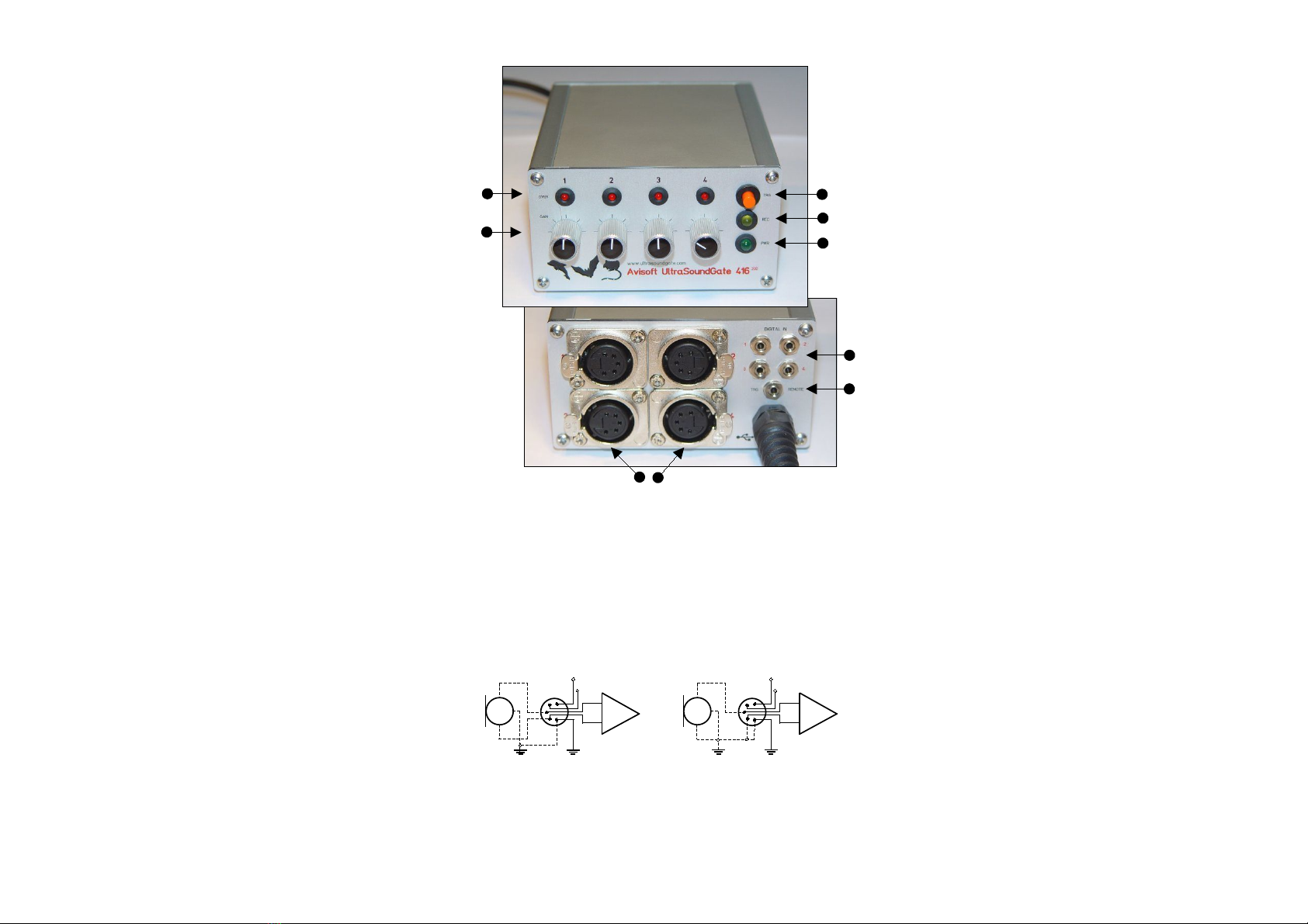
Components of the UltraSoundGate 416-200
7
1
5
4
2
Introduction
Thank you for purchasing UltraSoundGate 416. This device allo s
high-speed data acquisition at sampling rates of up to 750 kHz. In
conjunction ith the accompanying soft are Avisoft-RECORDER
USG, sound-activated direct-to-disk recording and real-time
spectrogram display is supported. The integrated high-quality
analog-to-digital converter ith adaptive anti-aliasing filter provides
best performance. The trigger button supports remote-controlled
harddisk recording. The rugged and compact design and the USB
interface make this device the optimal choice for portable
ultrasound recording in the field.
Getting started
The UltraSoundGate device appears to the PC as a standard audio
recording interface. Therefore, any sound recording application can
be used to operate this device. Ho ever, please note, that only
certain sampling frequencies are supported (see table Sampling rates,
resolutions & oversampling).
The recording soft are Avisoft- ECO DE USG is specifically
adopted to this device and ill support all UltraSoundGate features.
After installation, this soft are can be launched from Start /
Programs / Avisoft / ECO DE USG (rec_usg.exe).
First go to Options / Configuration and select the desired
sampling rate from Input-Device Settings / Sampling rate. Click
Ok. Then click at the Pause button (Monitoring/Pause) and the
Start button (Monitoring/Start). You ill then see the real-time
spectrogram displaying data acquired by the UltraSoundGate. For
details on the operation of the RECORDER soft are see the
Avisoft-RECORDER manual and the section Software Settings in
this guide.
Installation procedure
Hardware Installation
Simply connect the UltraSoundGate to an USB port. An USB Audio
Device and a HID device ill be detected automatically. On the
device, the green POWE LED should light and the amber LED
labeled EC should flash once it is connected to the PC. There is
no further user-interaction required. Only in Windo s 98, the Add
New Hardware Wizard dialog box ill appear and you should
follo the the instructions. To check, hether the device has
successfully been installed you may go to “Start->Settings->Control
Panel->System->Device Manager”. Check the “USB Audio Device”
under “Sound, video and game controllers” and the “Input devices
(Human Interface Device)”. There should appear an “USB-HID
(Human Interface Device)“ representing the trigger button.
Software installation
If you have also purchased the recording soft are “Avisoft-
RECORDER USG”, that is required to use the trigger button, you
ill need to install the Avisoft soft are from the accompanying CD-
ROM. In Windo s 2000 and XP you have to log on as
Administrator. The installation program setup.exe ( hich usually
starts automatically) ill install both the Avisoft-RECORDER and
the SASLab Pro soft are.
8
3
6
1 XL input connectors
The 5-pole XLR input connectors represent the analog inputs of the
recording device and provide po er supply voltages for external
amplifiers and microphones. The connector scheme is as follo s:
2 T G EMOTE
This 2-pole (mono) 2.5 mm mini-jack connector is electrically
connected to the TRIGGER button (5) and allo s connecting an
external trigger. This input is TTL-compatible (there is an internal pull-
up resistor of 10 kOhm to +5V). Pulling this input to ground (e.g. by
closing a s itch) ill activate the internal virtual joystick button.
1
2
3-
+
differential source
4 +5V supply voltage (max current 20 mA)
5 +200V polarization voltage (only model 416-200)
45
+200V
+5V
1
2
3-
+
single-ended source
45
+200V
+5V
3 DIGITAL INs
These 2-pole 2.5mm mini-jack connectors allo to connect external
digital signals. These inputs are TTL-compatible (internal pull-up
resistor of 10 kOhm to +5V). The status of the digital inputs is
stored in the LSB (bit 0) of the 16-bit data ords that are transmitted
over the USB and can be extracted after ards by the Avisoft-
SASLab Pro sound analysis soft are (e.g. for creating labels). The
digital input is not available in the 8-bit recording mode. Once a plug
is connected to this digital input, the available resolution is reduced
to 15 bits (the LSB is discarded).
4 Overload indicators
These red LEDs indicate clipping (over-modulation).
5 T IGGE button
The silver-colored trigger button is represented to the operating
system as a standard joystick button that can be used to start and
stop hard-disk recording in conjunction ith the Avisoft-RECORDER
soft are. To enable this mode of operation, the trigger type
Joystick button1 / USG Button must be selected from the
Configuration dialog (menu Options/Configuration). If the
TRIGGER button is pressed for more than t o seconds, the virtual
joystick button1 ill be activated permanently. This is indicated by
the flashing REC indicator (6). The virtual button1 can then be reset
(stop recording) by pressing the TRIGGER button again (the amber
LED ill be s itched off). This feature may be useful for recording
longer sequences. If this auto-hold behavior is not desired, one of
the other virtual joystick buttons may be used instead:
6 EC indicator
This amber LED ill flash once the device is connected to the PC. It
ill be s itched off permanently hen a sound recording application
is streaming audio data. It ill light again permanently as long as
the TRIGGER button is being pressed (representing the state of the
joystick button). If the TRIGGER button is pressed for more than 2
seconds, it ill start to flash.
7 POWE indicator
This green LED ill light as long as the device is connected to the
USB. In case the computer or HUB is unable to provide the required
supply current (because there are other devices connected or the
batteries of the laptop are empty), this LED ill be s itched off.
8 ecording level controls
These control knobs adjust the analog input recording levels for
each channel.
9 USB connector cable
Connect the UltraSoundGate 416 to a USB 1.1 or USB 2.0 port of a
computer.
button1: represents the state of the button for the first 2 seconds, then auto-hold mode
button2: represents the state of the TRIGGER button (no auto-hold)
button3: represents the inverse state of the TRIGGER button (no auto-hold)
button4 : changes its state each time the TRIGGER button is pressed (toggle mode)