AVLinx AVS 4.1 User manual

www.avlinx.com
Printed in the United States
AVLinx
Instruction Manual
2004 AVLinx Systems LLC
HDTV Switch
ModelAVS 4.1

Safety Precautions
RISK OF ELECTRIC SHOCK
DO NOT OPEN
2 3
Safety Instructions
CAUTION: PLEASE READ AND OBSERVE ALL WARNINGS AND
INSTRUCTIONS GIVEN IN THIS MANUAL.
1. Do not expose this unit to rain or moisture.
2. Do not expose this unit to high heat.
3. Do not install this unit near any heat sources.
4. Do not remove the cover at any time. Refer all servicing to qualified
personnel only.
Introduction Table of Contents
Thank you for your purchase of the AVLinx AVS4.1 HDTV Switch. At AVLinx, we are
motivated by a passion for quality audio/video equipment that fulfills the
technological needs of our customers. Every item we sell is designed to provide
the ultimate in signal integrity, system integration, and user control.
This product has been designed and manufactured to accommodate up to four
HDTV audio and video signal inputs to a single output. For the best results when
using this product, we recommend that you take the time to read through this
manual before you attempt to connect it to any other equipment. This manual will
accustom you to the various system connections and operating features
associated with this product. Keep this manual in a safe place for any future
reference.
In the spaces provided below, record your model and serial number. Refer to these
numbers when trying to acquire information or servicing requirements for this
product.
Model: ___AVS4.1______ Serial Number: _____________________
CAUTION: TO REDUCE THE RISK OF
FIRE OR ELECTRIC SHOCK, DO NOT
DISASSEMBLE. DANGEROUSLY HIGH
VOLTAGES ARE PRESENT INSIDE
THE UNIT. REFER SERVICING TO
QUALIFIED PERSONNEL ONLY.
!
WARNING
RISK OF ELECTRIC SHOCK
DO NOT OPEN
Introduction
Safety Precautions
Safety Instructions
Table of Contents
Identification
Accessories
Front Panel
Back Panel
Remote Control
-Operating Range
-Inserting Batteries
The AVS4.1
Controls
The RS-S232 Communication Port
Connections
Component Video Connections
Analog / Digital Audio Connections
Operations
Changing the Unit’s Power State
-Using the Input Selector Button
-Using the Remote Control
-Using the RS-232 Communication Port
Switching inputs
-Using the Input Selector Button
-Using the Remote Control
-Using the RS-232 Communication Port
Using an Alternate Remote Control
Programming an Input Selector Key
Programming a Power Button
-Power On/Off
-Power On Only
-Power Off Only
Restoring Default Remote Control Codes to the Unit
Troubleshooting
Warranty
Limited Warranty
Limitation of Liability
Servicing
Specifications
Appendices
2
2
2
3
4
4
4
4
5
5
5
6
6
6
6-7
6
6
8-9
8
8
8
8
9
9
9
9
10-12
10
11-12
11
11
12
12
13-14
15
15
15
16
16
17-18

The following items are included with this product:
9V 250mA wall power pack Infrared remote control
4 rubber mounting feet
The following items are optional accessories that can be purchased to accompany
this product:
Rack mount brackets DB9 Cable
Audio/Video Cables
For best results when using this
remote, point the signal
transmitter on the remote control
at the IR sensor window from no
more than 30 feet away and at an
angle of no more than 45
degrees.
45
Accessories
Front Panel
Remote Control - Operating Range
AV L inx
1
3
4

The AVS4.1 comes standard with four component video inputs, each paired with
digital and analog audio connections that pass the full HDTV bandwidth through
the signal paths. The passive switch design for all analog signals minimizes
distortion from active components. The AVS4.1 is also compatible with other high-
end video formats like RGBHV and S-Video with proper cabling.
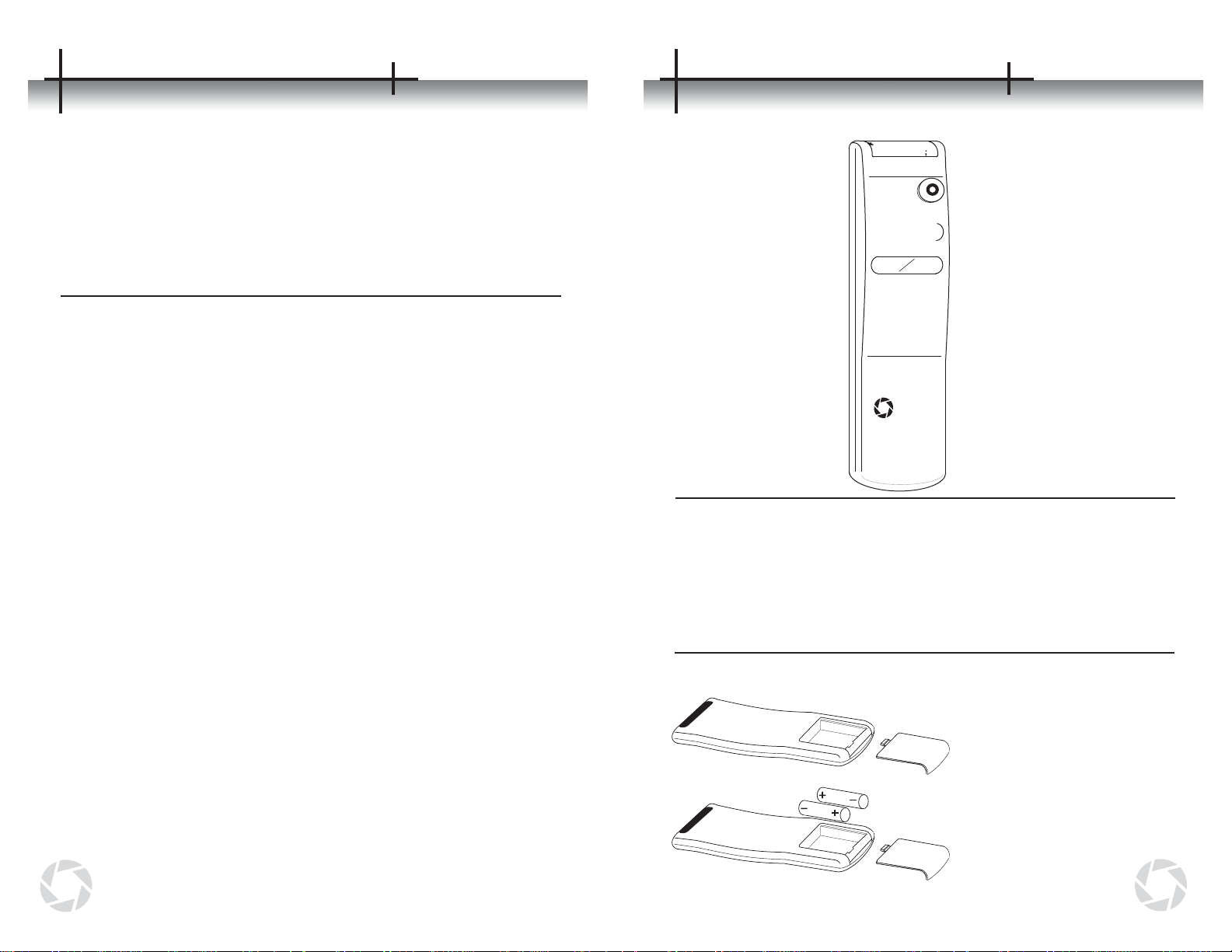
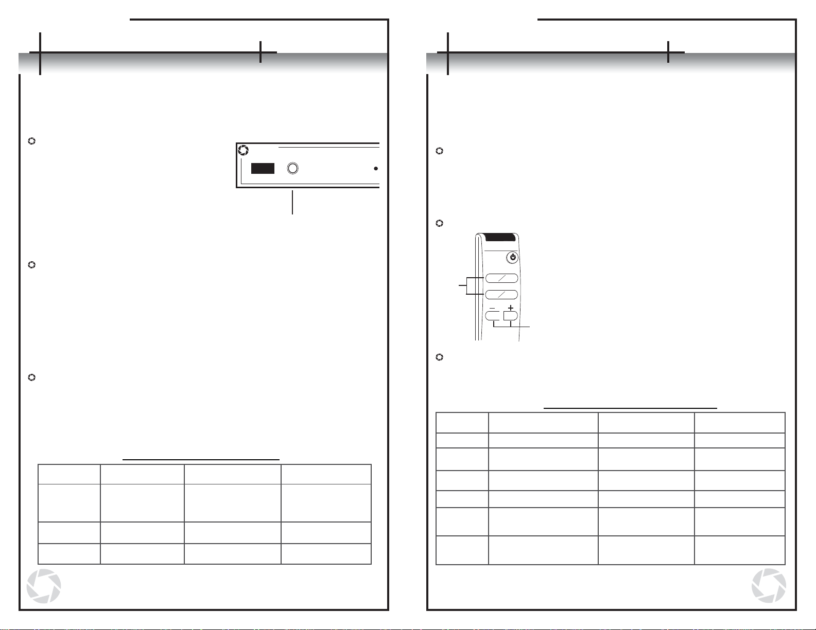
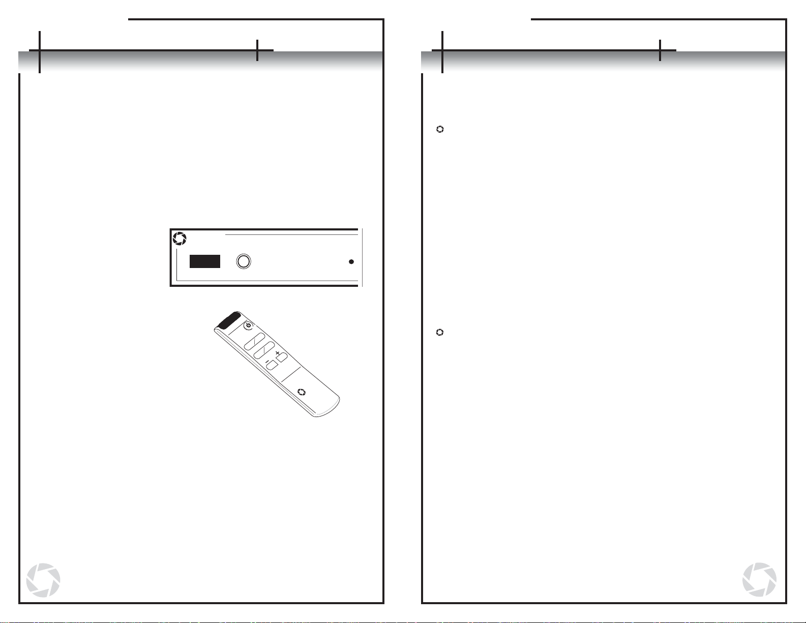
Controls
The unit includes a seven-button custom remote control, as well as controls on
the unit itself, that allow the user to switch easily between up to four high-
bandwidth sources. The AVS4.1 is also programmed with the ability to learn
new codes from other remote controls for executing all of its functions.
RS-232 Communication Port
Aside from standard audio/video inputs on the rear of the unit, the AVS4.1
includes a RS-232 communication port as an optional way of controlling the
unit. It interfaces well with system controllers, such as those made by Crestron
and AMX, or it can simply be connected to a home PC and issued commands
via a terminal program, such as Microsoft HyperTerminal. All the features
accessible through the remote control are also accessible via the RS-232
communication port. For detailed technical information, please see Appendix B
on pages 17-18.
Connections
Connections
The AVS4.1
67
Component Video Connections
The AVS4.1 is designed to switch a variety of audio and video signals, but most
users will choose to use it in a component video application as shown on page 7.
- For this usage, connect the corresponding red (Pr or Cr), green (Y), and
blue (Pb or Cb) outputs of a component video source to the same
connectors on the chosen AVS4.1 input.
- To connect the output of this unit, connect the three component outputs on
the AVS4.1 to the corresponding red (Pr or Cr), green (Y), and blue (Pb or
Cb) inputs of a component receiver (TV, projector, A/V receiver, etc.).
- (NOTE: For component video connections, 75-ohm component video
cable with red, green, and blue labeled connectors must be used. Other
types of cable cannot be used without sacrificing signal quality.)
Analog / Digital Audio Connections
In addition to video signals, the AVS4.1 can be used to simultaneously switch
analog audio or digital audio signals
- Standard analog audio may be connected by matching the red and white
analog audio outputs on the source to the red (R/V) and white (L/H) RCA
connectors on the chosen AVS4.1 input.
- Digital audio may be connected using either digital coax (SPDIF) or
optical (Fiber) formats. The chosen output from the digital audio source is
simply connected to the chosen AVS4.1 digital audio input through the
proper cable type.
- Coax and optical formats transmit the same data over different mediums,
so if a source has both types of outputs the user may choose to use
whichever is more convenient.
- Never connect both a digital coax cable and an optical cable to the same
input number at the same time. Data errors will result. Both types,
though, may have their outputs connected simultaneously if desired.
- (NOTE: For the coaxial digital audio connections, 75-ohm digital audio
cable should always be used. Other types of cable cannot be used
reliably in all situations.)
Other Connections
The AVS4.1 is capable of switching signals for other types of video formats such
as composite, S-Video, and RGBHV. Each of the individual signals in these
formats can be switched through the AVS4.1 using a proper converter to interface
with the RCA jacks at the input and output. Please note that the AVS4.1
does not convert signal formats from one type to another, so each
signal path from all inputs to the corresponding output should use
the same signal format.
Typical Component Video Connections
Input 1
Optical Audio
DC 5V
RS-232
www.AVLinx.com
L/H R/V SPDIF
Pr/R Y/G Pb/B
L/H R/V SPDIF
Pr/R Y/G Pb/B
L/H R/V SPDIF
Pr/R Y/G Pb/B
L/H R/V SPDIF
Pr/R Y/G Pb/B
L/H R/V SPDIF
Pr/R Y/G Pb/B
Output
Input 2 Input 3 Input 4 Output
4321
HDTV Tuner
Satellite Box
DVD Player
Video Game Console
High Definition Television

Switching Inputs
There are three ways to switch inputs on the unit: using the input selector button
on the front panel, using the remote control, and using the RS-232
communication port. An audible click will be heard whenever there is a change in
the power state of the unit.
Using the Input Selector Button
- Pressing the input selector button on the front panel will select the next
input following the active input. The green LED on the front panel will
designate the input that is presently selected.
- (NOTE: Refrain from holding the input selector button down for a
period longer than two seconds. See pages 10-12 for details.)
Using the Remote Control - The direct input keys can be used to select
the corresponding input on the unit. The
green LED on the front panel will designate
the input that is actively selected.
- The + and – keys can also be used to select
inputs. By pressing the + key, the unit will
switch to the next input following the one
actively selected. By pressing the – key, the
unit will move to the input preceding the one
actively selected.
Using the RS-232 Communication Port
- Through the RS-232 communication port, the user can select a
respective input by entering one of the following codes to coordinate
with the desired task.
Changing the Unit’s Power State
Once the unit is plugged in, the power state can be changed in one of the following
three ways. An audible click will be heard whenever there is a change in the power
state of the unit.
Using the Input Selector Button
- Pressing the input selector button
on the front panel once while the
unit is turned off will power the unit
on. The last known active input will
be selected and will be indicated by
the green LED on the front panel.
- (NOTE: Do not hold the input
selector button down for a period
longer than two seconds. See
pages 10-12 for details.)
Using the Remote Control
- Pressing the power key on the remote control will cause the unit to turn
on or off depending on its current power state.
- When turning the unit on, the last known active input will be selected and
will be indicated by the green LED on the front panel.
- Pressing any of the direct input keys on the remote while the unit is off
will cause the unit to power on with that selected key’s input becoming
active immediately.
- Pressing either the + or – key on the remote while the unit is off will
cause the unit to turn on with the last known active input selected.
Using the RS-232 Communication Port
- Through the RS-232 communication port, the user can change the power
state by entering one of the following codes to coordinate with the
desired task.
AVLinx
Inputs
1
9
8
Operations Operations
RS-232 Power State Commands
Command Function Response Verbose
On Response Verbose
Off
PT<cr>
P1<cr>
P0<cr>
Toggle On/Off
Turn power on
Turn power off
AP<cr><lf>
AP<cr><lf>
AP<cr><lf>
Py<cr><lf>where y
is the new power
state
P1<cr><lf>
P0<cr><lf>
(See Appendix B on page 17-18 for more details on the
RS-232 operations.)
1
3
4
2
Direct
Input
Keys
Input
Selector
Keys
RS-232 Input Selection Commands
(See Appendix B on page 17-18 for more details on the
RS-232 operations.)
I1<cr><lf>
I2<cr><lf>
I3<cr><lf>
I4<cr><lf>
Ix<cr><lf>, where x is
the new input
Ix<cr><lf>, where x is
the new input
AI<cr><lf>
AI<cr><lf>
AI<cr><lf>
AI<cr><lf>
AI<cr><lf>
AI<cr><lf>
Function Response Verbose
On
I1<cr>
I2<cr>
I3<cr>
I4<cr>
I+<cr>
I-<cr>
Response Verbose
Off
Command
Increment active input
by 1
Decrement active
input by 1
Switch active input to 1
Switch active input to 2
Switch active input to 3
Switch active input to 4
Input
Selector
Button

The AVS4.1 comes preprogrammed to recognize command codes from the
supplied AVLinx remote control. An alternate remote can be used in place of the
supplied remote. The original AVLinx remote control can be used to program most
universal remote controls by following the instructions for that product. Universal
and pre-programmed remote users may also choose to teach the AVS4.1 a new
set of pre-programmed codes. A small sample list of compatible manufacturers’
codes is listed in Appendix A on page 17. Please consult your universal remote
documentation on how to set pre-programmed codes. When an alternate remote is
configured with a suitable pre-programmed code set, the AVLinx remote functions
can be assigned to the alternate remote by performing the following steps:
Programming Input Selector Keys
1.Turn the unit on.
2.Make sure there are no
other infrared remote
control signals
interfering with the
unit during the
programming process.
3.Press and hold the
input selector button
on the front panel for
5-10 seconds. Continue
holding the button until
all steps are completed.
4.Aim the supplied AVLinx
remote directly at the
IR sensor window
and press the key
you are reassigning.
5.If the unit recognizes
that command, the active
input’s green LED
will turn off briefly
then come back on.
6.Aim the new remote that
is to be used for programming
directly at the IR sensor window and
press the key that will be performing the
desired function.
7.If the unit recognizes the command on the new remote, the active
input’s green LED will blink twice to confirm that the unit has set the new
key code.
8.Repeat Steps 1-7 for the remaining direct input selector keys.
Programming a Power Key
A power key can be programmed to perform one of three different tasks: turn the
unit on or off in a toggle progression, only turn the unit on, or only turn the unit off.
Power On / Off
1. Turn on the unit.
2. Make sure there are no other infrared remote control signals
interfering with the unit during the programming process.
3. Press and hold the input selector button on the front panel for 5-10
seconds. Continue holding the button until all the steps are
completed.
4. Aim the supplied AVLinx remote directly at the IR sensor window and
press the power key. The active input’s green LED will turn off briefly
then come back on to recognize that the unit has begun the
sequence to reassign a power key.
5. After the LED comes back on, press the power key on the AVLinx
remote again. This tells the unit that the user is reassigning the
power toggle feature.
6. Aim the new remote at the IR sensor window and press the key that
will now be controlling the power toggle feature of the unit.
7. If the unit recognizes the new command on the new remote, the
active input’s green LED will blink twice to confirm that the unit has
set the new key code.
Power On Only
1. Turn on the unit.
2. Make sure there are no other infrared remote control signals
interfering with the unit during the programming process.
3. Press and hold the input selector button on the front panel for 5-10
seconds. Continue holding the button until all the steps are
completed.
4. Aim the supplied AVLinx remote directly at the IR sensor window and
press the power key. The active input’s green LED will turn off briefly
then come back on to recognize that the unit has begun the
sequence to reassign a power key.
5. After the LED comes back on, press the + key on the AVLinx remote.
This tells the unit that the user is reassigning the power on feature.
6. Aim the new remote at the IR sensor window and press the key that
will now be controlling the power on feature of the unit.
7. If the unit recognizes the new command on the new remote, the
active input’s green LED will turn off for a second and then blink
twice to confirm that the unit has set the new key code.
10 11
Using an Alternate Remote
AV L inx
1
3
4
2
AV L i n x
Inputs
1

Power Off Only
1. Turn on the unit.
2. Make sure there are no other infrared remote control signals
interfering with the unit during the programming process.
3. Press and hold the input selector button on the front panel for 5-10
seconds. Continue holding the button until all the steps are
completed.
4. Aim the supplied AVLinx remote directly at the IR sensor window and
press the power key. The active input’s green LED will turn off briefly
then come back on to recognize that the unit has begun the sequence
to reassign a power key.
5. After the LED comes back on, press the – key on the AVLinx remote.
This tells the unit that the user is reassigning the power off feature.
6. Aim the new remote at the IR sensor window and press the key that
will now be controlling the power off feature of the unit.
7. If the unit recognizes the new command on the new remote, the
active input’s green LED will turn off for a second and then blink twice
to confirm that the unit has set the new key code.
Restoring Default Remote Control Codes to the Unit
In the event that the default remote control codes need to be restored, the following
procedure should be followed.
1. Turn on the unit.
2. Making sure not to press any keys on the remote, press and hold the input
selector button on the front panel for 30 seconds until the active input’s
green LED turns off. This indicates that 30 seconds has elapsed and the
button can be released.
3. Release the input selector button. After the button is released, the green
LED will turn back on. This signifies that the codes have been reset to
their default settings.
12 13
Using an Alternate Remote
Before calling AVLinx for servicing assistance, review the following guide for a
possible solution to the problem.
Problem Cause Solution
The unit will not turn
on.
RS-232 port is not
working
Poor component
video picture.
-Power cord is not
connected.
-The outlet in the wall
connected to the unit is
turned off.
-Incorrect power pack is
being used.
-Cable not connected.
-Improper cable being
used.
-Commands not
formatted properly.
-Communication port
parameters incorrect.
-Cable too long.
-Cable not securely
fastened.
-Poor quality cable.
-Plug the cord securely into
the back of the unit as well as
the wall.
-Plug the unit into a non-
switched outlet or turn the
outlet switch on.
-Make sure to use the power
pack that was supplied with
the unit or a suitable
equivalent.
-Make sure the cable is
plugged in properly.
-Connect the proper RS-232
cable. If connecting to a
control system, make sure to
use the proper cable. A non-
standard cable is sometimes
specified.
-Be sure to use capital letters
and follow all commands with
a carriage return.
-Set the communication port to
the settings specified in this
manual.
-Cables over 5m may not work
at highest resolutions.
-Use thumbscrews to securely
fasten the cable to the
connector.
-Use high quality cable
especially at longest distances.
Troubleshooting

14 15
Troubleshooting
Problem Cause Solution
Alternate remote
does not work
The AVLinx remote is
not working.
Digital audio does not
work -Both optical and coax
cables are plugged into
a single input at the
same time.
-Improper cable is being
used with SPDIF
connection.
-Remote’s data format is
not compatible with the
AVS4.1.
-Alternate remotes that
use a different frequency
than the AVLinx remote
may have reduced
range.
-Batteries are low.
-The IR Sensor window
is blocked.
-Input selector button
was held for more than
45 seconds.
-Input selector button
was held for more than
45 seconds.
-Input selector button
was held for less
than 30 seconds.
Alternate remote has
a limited range.
Resetting default
remote control codes
did not work
-Be sure to only use one type
of connection at the input.
-Be sure to use 75-ohm digital
coax cables, especially for
long distances.
-Set the remote to one of the
recommended compatible
codesets.
-Try using a recommended
codeset that uses 38khz
carrier frequency.
-Replace batteries.
-Provide a clear line of sight
between the remote and the
IR sensor window.
-Follow procedures on page
12 for “Restoring Default
Remote Control Codes.”
-Perform steps again and
release the input selector
button after the green LED
goes off when 30 seconds
have elapsed.
-Perform steps again and
release the input selector
button after the green LED
goes off when 30 seconds
have elapsed.
(For any problems not addressed in this section, please refer to the Servicing
information on page 16 of this manual.)
Limited Warranty
AVLinx Systems LLC warrants this product to be free from defects in materials and
workmanship that adversely affect the operation described in this manual for a
period of one (1) year from the date of sale. This warranty applies to the original
owner of the product purchased directly through AVLinx Systems LLC or an
authorized reseller. AVLinx Systems LLC will have the option to repair or replace
defective equipment covered by this warranty at its sole discretion. Products that
have not been operated in accordance with the instructions contained in this
document, or have been subjected to abnormal conditions including, but not
limited to, physical abuse, electrical surges, excessive moisture, temperature
extremes or tampering will not be eligible for service under terms of the warranty
agreement. Products purchased from an authorized reseller needing eligible
warranty service should be returned to the point of sale. Warranty service for
products purchased directly from AVLinx Systems LLC as well as service for all
products not covered under the terms of the warranty, may be arranged by
contacting AVLinx Systems LLC. Products should not be returned to the factory for
any reason without first contacting AVLinx Systems LLC for instructions. The safe
and undamaged shipment of items to AVLinx Systems LLC is the responsibility of
the customer.
Limitation of Liability
All implied warranties regarding merchantability and fitness for a particular use are
limited to the valid warranty period. All other implied warranties are disclaimed.
AVLinx Systems LLC is not responsible for consequential, indirect, special,
incidental or other damages resulting from the use or attempted use of this
product, no matter how those damages may have occurred. These limitations shall
be in effect where permitted by law.
All of the information contained in this manual is believed to be accurate. AVLinx
Systems LLC will not be responsible for damages resulting from inadvertent
omissions or errors in the manual. The information contained in this manual and
the technical specifications of the ADV2.1 are subject to change without notice.
Warranty

Specifications
16 17
Servicing
If you have any questions concerning the servicing of this or any of our other
products, please contact us through one of the following:
Mailing Address: AVLinx Systems LLC Phone: (214)-764-4095
4760 Preston Rd Ste. 244-196 Fax: (214)-764-3978
Frisco, TX 75034
Email: [email protected]
Website: http://www.avlinx.com
If you have any comments or suggestions on how we can add more value to your
purchase or better serve your needs with future products or technical support,
please contact us through the following:
Email: [email protected]
DC 7.5-9 @200mA
2.0W Max.
4.5 lbs. (2.05 kg)
17"W x 6"D x 1.72"H (19"W with Rack Mount brackets)
41Mhz
160Mhz
HDTV AVS4.1
Power Supply
Power Consumption (standard operation)
Weight
Dimensions
Bandwidth (-.1dB)
Bandwidth (-3dB)
Appendices
Appendix A: Compatible Remote Control Format
The following are products whose remote control data format is compatible with
the AVS4.1. The format used by the AVS4.1 is the NEC type with a 38khz carrier
frequency. Many universal or multi-function remote controls are able to be
programmed to emulate the remote control codes from these products. By
configuring your system remote to transmit codes from these products, and
following the steps in the section “Using an Alternate Remote Control” on pages
10-12 to teach your AVS4.1 the new codes, the AVS4.1 will work with many of the
remote controls you already have. This is very advantageous to those with a
master system remote control or those wanting to reduce remote control by
consolidating functions onto fewer remotes. These products are a very small
sample of those whose data format can be recognized by the AVS4.1. Other
settings may be tried, and the default AVS4.1 codes may always be restored by
following the instructions in “Restoring Default Remote Control Codes to the Unit”
on page 12.
Phillips DVD
Emerson CD
Videosonic VCR
Abex TV
Minutz TV
Asha VCR
Appendix B: R-S232 Communication Port
The R-S232 port on the AVS4.1 can be used to control all aspects of the unit
including changing inputs, changing the power state, querying the input and power
states, and reading its firmware revision information. The RS232 USART* on the
AVS4.1 operates at 9600 baud, 8 data bits, 1 stop bit, and no parity bits, which
means that the unit issuing commands must be configured with those settings as
well. All commands issued to the unit should be terminated with a carriage return.
All responses from the unit are terminated with a carriage return followed by a line
feed.
When the power cord is connected to the AVS4.1 (regardless of the power on or off
state), the RS-232 communication port will send the code “AS<cr><lf>” to
acknowledge that the unit’s startup sequence has completed. Once this response
has been received from the AVS4.1, the unit is then ready to perform all functions.
See the following table for a listing of available commands and their arguments.
All commands that do not have some form of default response are acknowledged
with an ‘A’ followed by the associated command character from the table below.
The AVS4.1 has a verbose mode, which is disabled by default, that provides the
status of the input and power state every time the state changes. It is equivalent to
issuing a Get command to return status information. All R-S232 commands are
inhibited while the front input selector button is pressed, such as the case during IR
code programming and reset functions. If commands are sent wholly during these
events, they will be ignored.
*Universal Synchronous Asynchronous Receiver/Transmitter

Function Response Verbose
On
Command Response Verbose
Off
I1<cr><lf>
I2<cr><lf>
I3<cr><lf>
I4<cr><lf>
Switch active input to 1
Switch active input to 2
Switch active input to 3
Switch active input to 4
Increment active input
by 1
Decrement active input
by 1
Toggle the power state
Turn power on
Turn power off
Enable Verbose mode
Disable Verbose mode
Get the active input
Get the power state
Get the verbose mode
state
Get the firmware name
and revision
Ix<cr><lf>, where x
is the new input
Ix<cr><lf>, where x
is the new input
Py<cr><lf>, where y
is the new power
state
P1<cr><lf>
P0<cr><lf>
V1<cr><lf>
Not Applicable
Ix<cr><lf>, where x
is the active input
Py<cr><lf>, where y
is the power state
Vz<cr><lf>, where z
is the verbose mode
state
AVS4.1 Rev. X.X,
where X.X is the
revision number
I1<cr>
I2<cr>
I3<cr>
I4<cr>
I+<cr>
I-<cr>
PT<cr>
P1<cr>
P0<cr>
V1<cr>
V0<cr>
GI<cr>
GP<cr>
GV<cr>
GF<cr>
AI<cr><lf>
AI<cr><lf>
AI<cr><lf>
AI<cr><lf>
AI<cr><lf>
AI<cr><lf>
AP<cr><lf>
AP<cr><lf>
AP<cr><lf>
Not Applicable
AV<cr><lf>
Ix<cr><lf>, where x
is the active input
Py<cr><lf>, where y
is the power state
Vz<cr><lf>, where z
is the verbose mode
state
AVS4.1 Rev. X.X,
where X.X is the
revision number
ADV2.1 Recognized RS-232 Commands
18 19
Appendices
The RS-232 communications port will issue an error for the following situations.
The error will consist of ‘E’ followed by a decimal number and a carriage return and
line feed. E2 – Command not valid
E3 – Argument (second character) for received
command not valid
E6 – RX buffer overflowed
User Notes
Table of contents
Other AVLinx Switch manuals
Popular Switch manuals by other brands

D-Link
D-Link DGS-1016A Quick install guide

Econ
Econ 21440 Installation & operation manual

Aruba
Aruba 2930M Installation and getting started guide

Conrad Electronic
Conrad Electronic FAZ 3000-SE-2 operating instructions

Eaton
Eaton LSE-11 Original operating instructions

Tabs
Tabs TBGW100-915 Reference manual