AVMAT CHARGER 6 User manual

Charger 6 / Charger 12 rel. 1.3c -E- english, page 1 of 22
C
HARGER 6
/ 12
CHARGER 6
Emergency Power Supply
CHARGER 12
Emergency Power Supply
Ba ery charger for use in Voice Alarm Systems (VAS)
and Sound Systems for Emergency Purposes (SSEP)
Manual
english
Rel. 1.3c 190320
march 2019
s

Charger 6 / Charger 12 rel. 1.3c -E- english, page 2 of 22
CHARGER 6 / CHARGER 12
Compliant to:
EN-54-4:1997+A1:2 2+A2:2:2 6 & EN-121 1-1 :2 5
Declara ion of Conformi y - Cer ifica e of Performance No. 1438-CPR-0330
version 17. 5.2 13
Warnings
Read his User Manual horoughly before using he device.
Do no ouch in ernal elemen s of an opera ing device – doing so poses a risk of an elec ric
shock or burns.
Pro ec he device from he possibili y of any i ems or fluids en ering in – doing so poses a risk
of elec ric shock and device damage.
Do no cover ven ila ion openings – doing so may resul in device damage.
Provide a free space of a leas 10 cm a he sides of he device, enabling i s proper ven ila ion.
The device mus be supplied from mains wi h a pro ec ive ear hing erminal.
The device may in erfere wi h opera ion of sensible radio and elevision equipmen loca ed
nearby.

Charger 6 / Charger 12 rel. 1.3c -E- english, page 3 of 22
table of contents
0. table of contents..............................................................................................................................3
1. Technical Description ....................................................................................................................4
1.1 Intended use....................................................................................................................................4
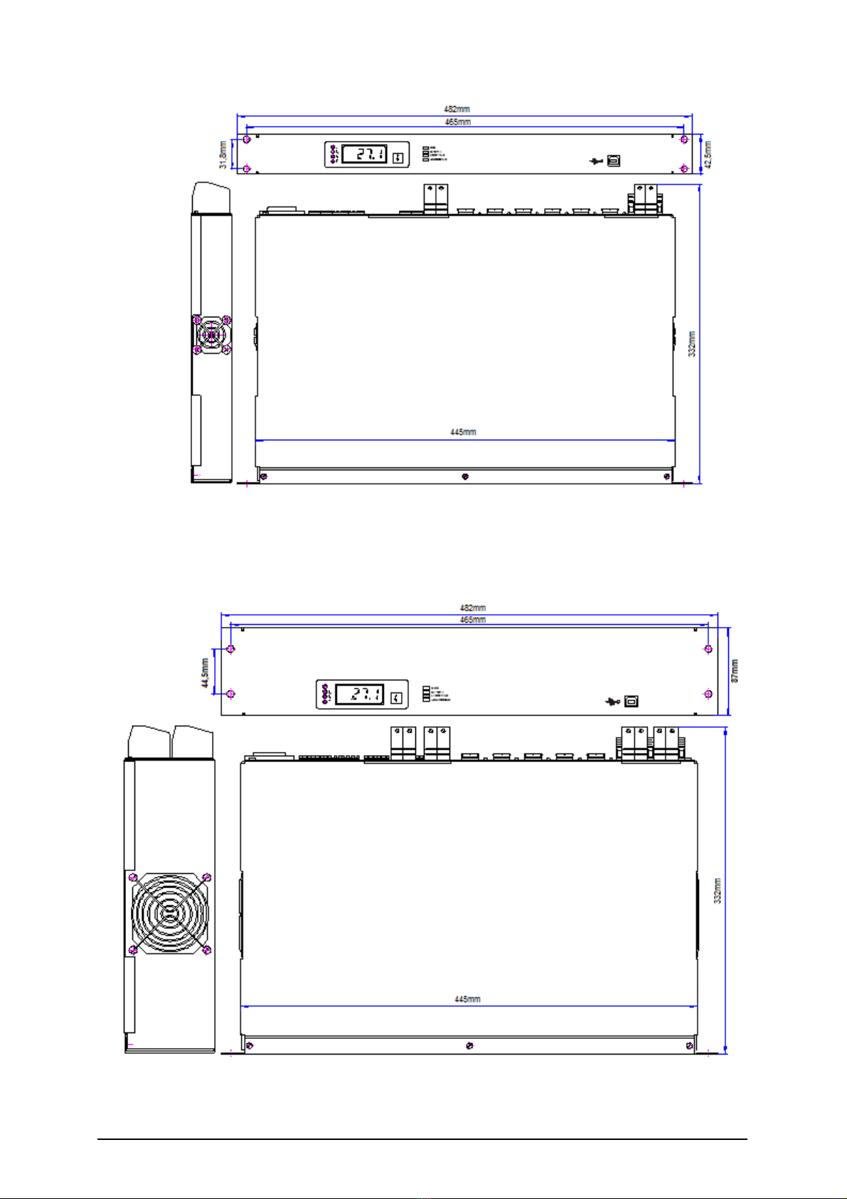
1.2 construction ....................................................................................................................................4
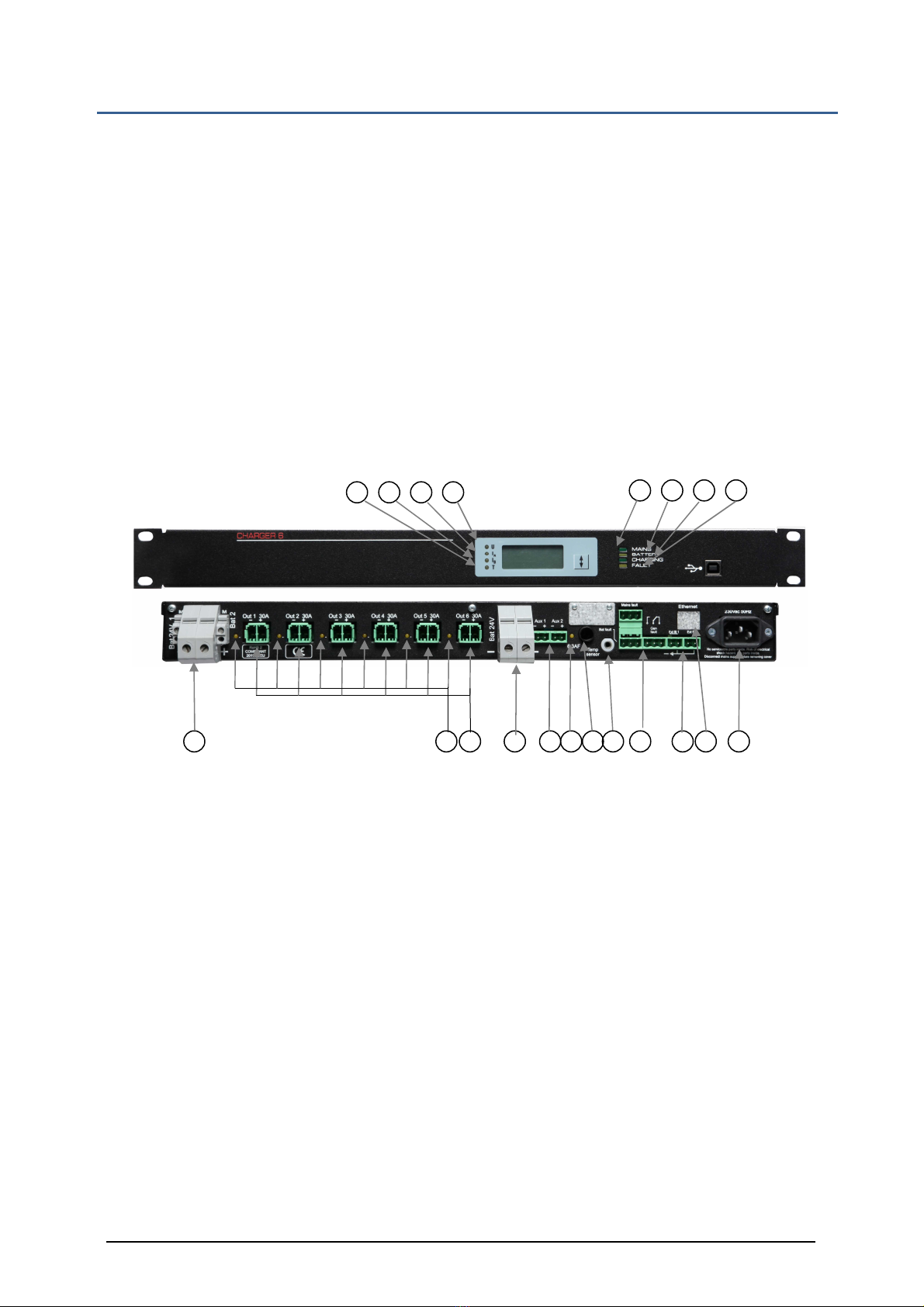
1.2.1 Battery charger CHARGER 6 ...................................................................................................6
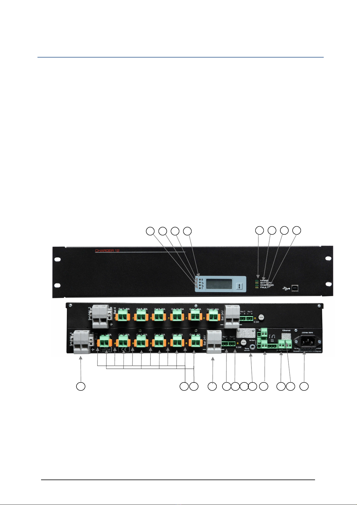
1.2.2 Battery charger CHARGER 12 ...................................................................................................7
1.3 Basic electrical parameters............................................................................................................9
1.4 Recommended working conditions...............................................................................................9
2 Operation principle...................................................................................................................... 10
3. Installation and connection .........................................................................................................13
3.1 Installation ....................................................................................................................................13
3.2 Connection ....................................................................................................................................13
4. Operation ......................................................................................................................................15
4.1 General information ....................................................................................................................15
4.2 Operation safety ...........................................................................................................................15
4.3 Digitale display ............................................................................................................................. 15
4.4 Digitale communication...............................................................................................................15
4.5 Operation state signaling.............................................................................................................16
4.6 Maintenance .................................................................................................................................17
5 Servicing........................................................................................................................................18
5.1 Circuit breakers ...........................................................................................................................18
5.2 Detecting faults and troubleshooting.......................................................................................... 19
6 Additional information ................................................................................................................ 19
6.1 Remarks of the manufacturer..................................................................................................... 19
6.2 List of indicated error codes........................................................................................................19
6.3 Handling packagings and used products ...................................................................................21

Charger 6 / Charger 12 rel. 1.3c -E- english, page 4 of 22
1. Technical Description
1.1 Intended use
The power supplies are intended to be used as power supply of voice alarm systems
(VAS), providing them with the backup battery power for acoustic amplifiers and
controllers and other VAS modules separately:
CHARGER 6 providing 6+2 outputs cooperating with one or two battery banks
CHARGER 12 providing 12+4 outputs cooperating with one or two battery banks
1.2 construction
The Power supplies are designed for installation in a typical 19” rack and are
assembled within a metal case:
CHARGER 6 19“ / 1 U ( 1 unit rackspace )
CHARGER 12 19“ / 2 U ( 2 units rackspace )

Charger 6 / Charger 12 rel. 1.3c -E- english, page 5 of 22
Fig. 1 View and nominal dimensions of CHARGER 6 power supplies.
Fig. 2 View and nominal dimensions of CHARGER 12 power supplies.

Charger 6 / Charger 12 rel. 1.3c -E- english, page 6 of 22
1.2.1 Battery charger CHARG R 6
The power supply unit is shipped together with:
1. The 23 V mains cable equipped with the IEC plug;
2. A temperature sensor;
3. Set of plugs for connecting power supply of VAS amplifiers (6 pcs. of the PC 5/2-ST-1-7 plugs);
4. Set of plugs for connecting power supply of VAS controllers (2 pcs. of the MSTB2,5/2-ST plugs);
5. Set of plugs for connecting inputs and outputs of the indication system
(5 pcs. of the MSTB2,5/2-ST plugs)
Adigital display panel, a USB port and 4 LED indication diodes are installed in the front panel of
the power supply unit:
A: U – ba ery vol age
B: IA – curren for con rollers
C: IB – curren of charge/disacharge
D: T – ba ery empera ure
1. Mains - (green)
2. Ba ery - (yellow)
3. Charging - (green)
4. Faul - (yellow)
Fig. 3 View of the front and back panel of the CHARGER 6 power supply unit
The back panel contains:
1. A male IEC socket for connecting the mains cable (23 Vac 5 Hz).
2. Four screw connectors for connecting two 24 V battery banks (BAT1, BAT2) and two
neighbouring connectors of the circuit equalizing voltages of the battery banks M.
3. A socket for connecting the temperature sensor (TEMP SENSOR).
4. Two input sockets for external fault indication (EXT. FAULT 1 and EXT. FAULT 2).
5. Three output sockets of relay indication system (MAINS FAULT, BATTERY FAULT and GENERAL
FAULT).
6. 6 sockets for connecting VAS 24V amplifiers (from OUT1 to OUT6). They can also be used for
connecting the heat and smoke control system.
7. A double socket for connecting the network controller and other VAS modules designed for
work with 24V power supply (ADDITIONAL OUTPUT 24V).
8. LEDs to monitor output conditions of high current outputs
9. LEDs to monitor output conditions of high AUX outputs
1 . Connector “M” for battery balancer
11. Primary fuse 6.3 AF
12. Ethernet connector. ( optional )
D
C
B
A
1
2
3
4
2
8
6
2
A
1
7
5
4
3
9
11
10

Charger 6 / Charger 12 rel. 1.3c -E- english, page 7 of 22
1.2.2 Battery charger CHARG R 12
The power supply unit is shipped together with:
1. The 23 V mains cable equipped with the IEC plug;
2. A temperature sensor;
3. Set of plugs for connecting power supply of VAS amplifiers (12 pcs. of the PC 5/2-ST-1-7 plugs);
4. Set of plugs for connecting power supply of VAS controllers (4 pcs. of the MSTB2,5/2-ST plugs);
5. Set of plugs for connecting inputs and outputs of the indication system
(5 pcs. of the MSTB2,5/2-ST plugs)
A digital display panel, a USB port and 4 LED indication diodes are installed in the front panel of the
power supply unit:
A: U – ba ery vol age
B: IA – curren for con rollers
C: IB – curren of charge/disacharge
D: T – ba ery empera ure
1. Mains - (green)
2. Ba ery - (yellow)
3. Charging - (green)
4. Faul - (yell
Fig. 4. View of the front and back panel of the CHARGER 12 power supply unit
D
C
B
A
1
2
3
4
2
8
6
2
A
1
7
5
4
3
9
11
10

Charger 6 / Charger 12 rel. 1.3c -E- english, page 8 of 22
The back panel contains:
1. A male IEC socket for connecting the mains cable (23 Vac 5 Hz).
2. Four pairs screw connectors for connecting up to four 24 V battery banks (BAT1, BAT2,
BAT3, BAT 4) and four neighbouring connectors of the circuit equalizing voltages of the
battery banks M.
3. A socket for connecting the temperature sensor (TEMP SENSOR).
4. Two input sockets for external fault indication (EXT. FAULT 1 and EXT. FAULT 2).
5. Three output sockets of relay indication system (MAINS FAULT, BATTERY FAULT and
GENERAL FAULT).
6. 12 sockets for connecting VAS 24V amplifiers (from OUT1 to OUT12).
7. 4 sockets AUX 1 .. AUX 4 for connecting controllers and other VAS modules designed for
work with 24V power supply (ADDITIONAL OUTPUT 24V).
8. LEDs to monitor output conditions of high current outputs
9. LEDs to monitor output conditions of high AUX outputs
1 . Connector “M” for battery balancer x2
11. Primary fuse 6.3 AF x2
12. Ethernet connector. ( optional )

Charger 6 / Charger 12 rel. 1.3c -E- english, page 9 of 22
1.3 Basic electrical parameters
CHARGER
6
CHARGER
12
Nominal mains voltage 230V +10% -15% 50Hz
Power factor 0.94
Efficiency (while charging the battery) 84 %
Output voltage stabilisation 0.5 %
Leakage current in the protective cable
<1.5
mA
<3
mA
Maximum input current
2.7
A
5.4
A
Nominal voltage of the external battery bank
24
V
24
V
Nominal voltage of the floating mode operation at 25°C
27.1
V
27.1
V
Nominal voltage of the bulk charging mode operation at 25°C
28.3
V
28.3
V
Temperature compensation factor of the floating mode operation and bulk
charging - 48 mV/ºC) - 48 mV/ºC)
Maximum capacity of supplied battery banks
43
Ah *2)
86
* 2)
Maximum number of battery strings
2
4
Maximum charging current
16
A *2)
32
A *2)
Maximum growth of resistance of battery circuit *1)
25
m
Ω
25
m
Ω
Load capacity of power supply outputs provided for VAS amplifiers
6 x 3
A
12 x 3
A
Load capacity of power supply output provided for network controller and
other VAS modules 1x6 A 2x6 A
The quiescent current consumption from the battery
< 4
mA
< 8
mA
Current consumption from the batteries after LVD disconnection
< 5m
A
< 5m
A
Range of output voltage *3)
21. …28.8
V
21. …28.8
V
Maximum current which the power supply unit can take from a single
battery when the main power supply is cut off or disconnected [A] 9 A 9 A
*1) Guaranteed value of battery circuit resistance, at which the fault indication system is switched on
for each battery string separately.
*2) Listed battery capacities do not include current consumption from 24V outputs provided for the VA controller .
*3) The listed range includes voltage values between the voltage of a discharged battery bank (at the end of the buffer mode
cycle) and the value of the bulk charging mode voltage, including temperature compensation
1.4 Recommended working conditions
Relative humidity max. 8 %
Direct sunlight exposure inadmissible
Strokes during operation inadmissible
Ambient temperatures
Limits of acceptable storage temperature -4 …+85C
Working temperature -5 … +45C
class 3K5 according to EN 60721-3-3

Charger 6 / Charger 12 rel. 1.3c -E- english, page 10 of 22
2 Operation principle
The microprocessor controller checks the presence of the mains power, battery state, state of
external alarms inputs and a number of internal parameters (e.g. acceptable time of the bulk
charging).
If an improper operation of the device is detected, a fault indication is generated.
This operational state is signalled by corresponding diodes, lighting up in the front panel, and by
three remote indication relays accessible in the back panel. The relays are activated, when no
fault indications are being generated; it means that a fault indication causes deactivation of the
relay.
The power supply circuit is based on a direct floating mode system. The power supply, supplied
from the mains, is connected in parallel with an external battery bank.
The VAS amplifiers supplied with their own power supplies are required not to consume power
from the 24V voltage. However, when power failure, they should automatically switch over to
use the battery power supply.
Figs. 5a. and 5b. below present flowcharts of both power supplies
Fig.5a Block diagram of CHARGER 6 power supply

Charger 6 / Charger 12 rel. 1.3c -E- english, page 11 of 22
Fig.5b Block diagram of CHARGER 12 power supply

Charger 6 / Charger 12 rel. 1.3c -E- english, page 12 of 22
When the mains present, the power supply maintains the external battery banks in their fully charged
state. Power supply’s operation is controlled by the microprocessor controller, which independently
supervises the batteries, maintaining the floating mode voltage in them (depending on ambient
temperature, if the external temperature sensor has been connected). This sensor should be located
near the battery. If the sensor is absent, the controller maintains voltage corresponding to the
ambient temperature of 25°C.
In case of power failure, the loads connected to the power supply are supplied directly from the
battery bank – this is the battery mode. As the mains power supply returns, the battery bank charging
current is above the set point, the power supply proceeds to the bulk charging mode.
This mode is characterized by charging using limited current at the increased voltage. The end of the
bulk charging at a fully operational battery bank is defined by a significant drop of charging current
after the preset charging voltage has been reached, after which the power supply decreases the
voltage to the level of floating mode voltage, continuing charging at this voltage. If the battery bank is
faulty, the bulk charging is interrupted in the fault mode after the maximum, preset charging time has
been exceeded or when the permissible ambient temperature of the battery bank is exceeded.
The circuit of the CHARGER 6 or CHARGER 12 power supply is equipped with a Low Voltage
Disconnector (LVD) – an internal switch of deep discharge implemented in the relays in their output
circuits (one relay in each circuit for powering one amplifier and one at each double outputs for
powering the VAS controller). They disconnect the outputs from the battery banks when the battery
reaches the minimum permissible discharge level, thus preventing it from further discharging and
preventing it from being destroyed.
The second RB disconnector – battery disconnector disconnects the additional outputs when
detecting short circuit in the battery circuit supplying power to the additional outputs from the
rectifier.
Measurement of battery circuit resistance is an additional function of the controller. The resistance
measurement takes place only in the floating mode operation. Detection of battery circuit resistance
increase caused by an increase in internal resistance of the battery or by an increase of battery
connection resistance, causes the indication for reaching high battery circuit resistance to be sent. If
the battery bank gets disconnected, the controller detects a significant increase of battery circuit
resistance and indicates a device configuration error.
The power supply is equipped with a function of voltage equalisation between batteries of each
battery string. Voltage equalisation takes place as a result of loading the half of batteries which exhibit
higher voltage, with a small current, of 1 mA. This function is called for if the voltage difference
exceeds .1V.
The use of voltage equalising circuit requires an additional connection to be introduced between the
M terminal of a given battery string and the median point of the battery itself. This system is resistant
to an incorrect connection of this connector (to an inappropriate terminal of any battery), indicating a
fault in such situations. The lack of this connection is automatically detected which results in switching
off the voltage equalising system.
The circuit of the CHARGER 6 or CHARGER 12 power supply is continuously controlling the state of
outputs fuses on each output for amplifier and controllers. A fault to any of them results in a fault
signal being generated (the signalling lights on the front panel of the power supply unit are switched
on and the remote signalling to be put out), and in addition, switching on a yellow LED diode located
near the faulted outputs.
When the power supply unit is switched on, state of load at the outputs designed for VAS amplifiers is
checked. Lack of current consumption from these outputs is required. If any of the amplifiers has e.g.
its own power supply switched off (or faulty), which results in an attempt of switching it on using
output voltage of the power supply unit, such the state shall be detected and the relay present at this

Charger 6 / Charger 12 rel. 1.3c -E- english, page 13 of 22
output shall not switch on, and, in addition, fault indication shall be switched on. Relays present at the
other outputs shall simply switch on, supplying voltage to operational amplifiers.
During the power supply start-up, the current consumption from the output designed for the VAS
controller is permitted only. Its load present at this output, however, decreases the current provided
for battery bank charging.
NOTES
If the system has already been switched on and any of the amplifiers starts current consumption using
output voltage as a result of fault, malfunction or disconnection of its individual mains power, the
power supply shall detect and indicate such the situation, if the current being consumed by the
outputs exceeds 1A. Leaving the power supply system in this state may eventually result in an
uncontrollable discharge of the battery, despite proper functioning of the power supply system itself.
3. Installation and connection
3.1 Installation
The power supplies have been designed and manufactured as a cassette offering the IP2 protection
rating, prepared for installation in a typical 19” rack using four mounting holes located in the front
panel (Fig. 1, 2).
The rack dedicated to the Voice Alarm Systems must have IP3 protection rating.
Installation of power supply units in the rack requires guide bars to be used. Guide bars supporting
the power supply cassette should be installed in such a way as not to impede the flow of air to the
fans located on the both sides of the cassette. A 1 cm ventilation space is required on both sides of
the case.
The power supply is not equipped with its own mains switch, thus it is necessary to use an adequate
switch in the power supply circuits (outside the power supply unit).
The required electric installation should be provided as a permanent installation equipped with an
overvoltage protection system.
3.2 Connection
connec ing o power supply ne work
Connecting the mains to the power supply should be implemented by using a 3-wire YLY-type cable
with the 1.5 mm2 cross-section, equipped with the IEC plug.
Load connec ion
The CHARGER 6 or CHARGER 12 power supply has been designed for connecting the VAS amplifier
modules supplied with the 24V voltage, and separately, the network controllers and other VAS
modules supplied with the 24V voltage.
The sockets located in the back panel allow for connection of single amplifiers with power of up to
5 W, using 2-pin connectors.
Amplifiers operating at higher power (maximum 1 W) should be simultaneously connected to two
outputs of the power supply unit.
If the main amplifier is equipped with its spare amplifier present in the VAS system, it is possible to
connect both amplifiers to the common power supply output (or two outputs for high power
amplifiers). However, this connection should be made excluding connectors of the power supply
units.

Charger 6 / Charger 12 rel. 1.3c -E- english, page 14 of 22
Plugs for output connection are supplied with the power supply unit. Maximum cross-section of the
connected wires is 6 mm2 in case of outputs provided for amplifiers and 2.5 mm2 for the 24V power
supply output providing power supply for the VAS controllers and other VAS modules.
The CHARGER 6 power supply is equipped with two power supply outputs for VAS controllers, while
the CHARGER 12 power supply unit is equipped with four such outputs. If the VAS system requires a
higher number of controllers and cooperating devices to be used, corresponding splitting should be
implemented outside the power supply unit.
connec ing ba ery bank
Power supply units are designed to cooperate with VRLA-AGM battery banks.
Note: Because the power supply unit is not equipped with a battery bank circuit breaker,
appropriate circuit breakers, separate for each of the battery banks, should be installed near each
positive terminal of each battery.
Connection of a battery set should be made using connector wires with a maximum cross-section of
16 mm2 for terminals located in the back panel of the power supply unit, marked as Bat taking a
proper care to provide them with a proper polarity. A reverse connection of a battery bank may result
in severe fault to the power supply unit itself, as well as in connected, external devices.
Positive terminal poles, marked with numbers, enable distinguishing of battery banks as each of them
is supervised separately. Negative poles are short-circuited together.
The M outputs of the voltage compensation circuit should be connected with the center of the
appropriate battery string by means of the cables of the cross section of .75mm2. The connection
must be protected near the battery with its own fuse of .5 ... 2AF.
Note: If only single battery path is used, so connect to Bat1
If two battery pathes were used, so connect to Bat1 and Bat2
If three battery pathes were used, so connect to Bat 1, Bat2 and Bat3
Minimum Akku capacity is 45Ah recommended is 65Ah or higher!
Remind maximum current for each battery-connector is 9 A
Connec ing ex ernal faul indica ion sys em
The power supply is equipped with two inputs for connecting external fault indication systems, the
sockets of which are located in the back panel. Corresponding plugs are supplied with the power
supply unit. One of the plugs has a factory pre-installed jumper and it has to be placed in the alarm
socket EXT. FAULT 1, even if this input is not used, since it is activated when its contacts become
disconnected.
The second input EXT. FAULT 2 is activated by short-circuiting its terminals.
External fault indication systems should be connected using fire resistant type cables (the cross-
section of .8 mm2).
Ou pu of remo e indica ion
Outputs of remote relay indication are implemented as 3-pin sockets. The power supply unit is
supplied with 2-pin plugs. You can use the normally connected (NC) or normally open (NO) contacts of
the internal indication relays by placing them in the appropriate socket. Remote indication circuits
should be connected by using fire resistant type cables (of the cross-section of .8 mm2)
Tempera ure sensor connec ion
The external temperature sensor supplied with the power supply unit should be connected to the
appropriate socket (Temp sensor). The sensor should be placed in a direct proximity of the battery bank,
if possible, between the walls of two adjacent batteries.

Charger 6 / Charger 12 rel. 1.3c -E- english, page 15 of 22
4. Operation
4.1 General information
Output voltages and signalling thresholds are preset as factory default values. Power supplies after
installing require supervision by the service team as some emergency states may occur during the
operation of the device.
4.2 Operation safety
The power supply unit is a Class I device according to the standard EN 6 95 -1:2 7/A1:2 11
(IEC95 ), designed for connecting to a permanent, one-phase installation using an earthing cable,
according to the HD 6 364-4-41:2 7 Standard Electric installations at construction sites.
The metal case of the power supply units is connected to a protective terminal (PE). The circuits used
for connecting the battery, remote indication outputs and remote indication inputs are separated
from power supply circuits and from the case.
Contacts of remote indication relays are completely separated from all other circuits (including output
circuits).
Inputs of external fault indications are located on the potential of negative bus of the battery bank.
The interference filters used in the CHARGER 6 and in CHARGER 12 power supplies are equipped
with the Y class capacitors causing the appearance of the leakage current in the protective conductor
of maximum 1.5 mA for the CHARGER 6 and 3mA in CHARGER 12.
4.3 Digitale display
Power supply units allow for digital measurements of basic operation parameters of the system:
current voltage of the supervised battery bank (U), its charging or discharging current (IB), current
consumed by the VAS controllers from the 24V power supply (IO) and of the ambient temperature (T),
if the temperature sensor has been connected. The current measurement type (selected by using the
vertical arrow button) is distinguished by switching on a LED diode with the corresponding marking. In
addition, one can read the error code detected by the power supply unit controller (all diodes
indicating measurement type are switched off). This position is active only then, when an operation
error has been detected in the system and the fault indication has been activated.
A list of particular errors (many errors can be caused by a particular type of fault) is performed by
using the vertical arrow button. The long press of the arrow button allows basic operation parameters
of the system to be measured, starting with U..
4.4 Digitale communication
The front panel of the power supply unit is equipped with a USB communication socket used routinely
for servicing. The servicing software allows for diagnostic works to be performed, enabling to check
numerous operation parameters of the power supply and to modify its default settings. This output is
galvanically insulated from all other circuits of the power supply unit.
Optionally, the power supply unit may be equipped with an Ethernet interface, enabling operation
within a TCP/IP network. It has two simple service servers implemented:
- a http server for presentation of the current system state as web pages available for browsing using
a web browser;
- ModbusTCP protocol server enabling device controlling and supervision.
Detailed information can be obtained from the manufacturer.-

Charger 6 / Charger 12 rel. 1.3c -E- english, page 16 of 22
4.5 Operation state signaling
The power supply is equipped with LED, sound and remote indication systems. The LED indication is
used in order to bring attention of the personnel to the operation state of the device and to inform
about the reason of a potential malfunction. The sound indication system is activated together with
the lighting signalling.
Fault indication is maintained as active until it is deactivated using the vertical arrow button located in
the display panel. Short press of the button switches the sound indication system off, while keeping
the LED and remote indication systems active. The remaining indication systems can be deactivated
by pressing and holding the vertical arrow button for over 5 seconds. However, the use of the key is
effective only when the reason triggering the event generation is no longer present. The indication
systems are reset automatically only when the network power supply is restored and external signals
at the EXT. FAULT 1 and EXT. FAULT 2 inputs are no longer detected. In the case of the power failure,
instead of a continuous sound signal, a short, intermittent signal is generated every 15 seconds.
The LED indication system comprises four LED diodes located in the front panel of the power supply.
Three diodes represent the current operation mode (MAINS - green, BATTERY - yellow, CHARGING -
green), and the fourth - fault (FAULT - yellow).
The remote indication system includes three sockets denoted MAINS FAULT, BATTERY FAULT and
GENERAL FAULT. Each of the sockets has three plugs, switched between by using relays, completely
separated from all other circuits. During normal, correct operation of the power supply unit, relay
coils are active. It means that Mains Fault (power failure) indication, Battery Fault and General Fault
indications are executed by switching the appropriate relay off (current loss in the relay coil).
The contact setting in this state (so called zero-voltage state) has been presented next to each
corresponding socket.
List of states of the LED and remote indication systems is presented in the tables below.
LED indication system in the front panel.
DESCRIPTION COLOUR STATE EVENT DESCRIPTION
MAINS green
on
Normal operation state at the mains present.
off
No mains or rectifier fault.
BATTERY yellow
on
Battery operation (no mains or rectifier fault).
off
Normal operation state at the mains present.
CHARGING green
pulsating
Bulk charging.
on
Charging during floating mode (after the bulk
charging has finished).
off
Charging has finished.
FAULT yellow
on
Fault occurred within the power supply unit or
external fault. Please read the error code from the
display in order to determine the reason.
pulsating
External fault indication at
EXT. FAULT 1
or
EXT. FAULT
2 input. *).
*) If it is sent together with the external fault indication an internal fault occurs, the LED diode FAULT
will be on continuously.

Charger 6 / Charger 12 rel. 1.3c -E- english, page 17 of 22
L
LED indication system in the back panel.
DESCRIPTION COLOUR STATE EVENT DESCRIPTION
From Ou 1
to Ou 12 yellow
on
Fault of output circuit breaker.
pulsating
Current is consumed from the particular output (the
indication is activated only before the outputs are
switched on).
off
Output switched on.
AUX yellow
on
Fault of circuit breaker of additional outputs
off
Output switched on.
Relay indication system.
DESCRIPTION STATE EVENT DESCRIPTION
MAINS FAULT
on
Normal operation state at the mains present.
off
No mains or
rectifier fault.
BATTERY FAULT
on
Correct battery operation.
off
High resistance of battery circuit or battery voltage below a preset
level (battery discharged).
GENERAL FAULT
on
No fault.
off
Fault within the power supply or external fault.
4.6 Maintenance
The device does not require any specific maintenance operations to be performed. During normal
operation of the unit care should be taken to maintain clean and tidy area around the power supply
unit.

Charger 6 / Charger 12 rel. 1.3c -E- english, page 18 of 22
5 Servicing
5.1 Circuit breakers
Fuse type circuit breakers are easily accessible for the service team. Their parameters have been
specified in the table below.
Protected circuit in the power supply Fuse type and value of
CHARGER 6
Fuse type and value
CHARGER 12
Amplifiers output circuits
– accessible after cover has been dismounted
(Fig. 6 - #2)
6 x 30AF (6,3x32mm) 12 x 30AF (6,3x32mm)
Additional output 24V circuit (Fig. 6 - #1)
1 x 6.3AF (6.3x32mm)
2 x 6.3AF (6.3x32mm)
Cau ion: If fuse replacemen requires he cover o be removed, i can be done only af er
disconnec ed he mains and from he ba ery bank.
The VAS system personnel can exchange the above mentioned fuses only. If other circuit breakers
used within the power supply unit are faulty, a repair performed by qualified service personnel is
required. Fig. 6 below presents location of the fuses inside the power supplies.
DL100
TR201
P 248.2
B200
#1
#2
14
1
8
8
71
K301K300
P 436.1
Fig. 6. Location of circuit fuses inside the power supply units.
A en ion
The 2U height power supply has two sets of sockets and fuses – the upper one and the lower one. To
access the upper fuses set, the screws that fix the upper shield (A), should be unscrewed. In order to
access the lower set of fuses, the screws (B) needs to be unscrewed and the upper set of fuses and
sockets needs to be raised.

Charger 6 / Charger 12 rel. 1.3c -E- english, page 19 of 22
A
B
OŚOBROTU
Fig.7. Access to the fuses in the 2U power supply version
5.2 Detecting faults and troubleshooting.
Most cases of malfunctions which can occur during device operation is indicated and handled by the
microprocessor installed in the device. The unit is equipped with 7 fuses (or 14 in the power supply of
the 2U height), replacement of which may be undertaken by qualified service personnel. These are
fuses of output circuits – amplifiers power supply and the VAS controller power supply or the heat
and smoke control system devices.
Output fuses may be faulty as a result of short-circuit of device outputs. The VAS controller power
output breakers are accessible directly on the rear panels of the power supplies. The VAS power
output breakers replacement requires the access described in the point 5.1.
Warranty and after-warranty repairs are performed by service of the manufacturer or by an
authorized service partner of the manufacturer.
6 Additional information
6.1 Remarks of the manufacturer
The manufacturer reserves the right to introduce construction and technology changes to the
product, without diminishing its quality
6.2 List of indicated error codes
Below, a list of codes accessible to the user is presented. It is possible to read the codes from the
digital display. It is possible only then, when the system has detected a fault and the fault indication
has been activated.
Codes denoted with the letter E indicate fault or error caused by an external factor. The letter P
indicates an internal cause within the power supply..
DREHACHSE

Charger 6 / Charger 12 rel. 1.3c -E- english, page 20 of 22
Descrip ion Code
Output(s) not disconnected
P 1
Output(s) loaded
E 2
Output(s) not connec
ted
P 3
Output circuit breaker(s) fault
E 4
Network controller 1 circuit breaker fault
E 5
Network controller 2 circuit breaker fault
E 6
External fault 1 *)
E 7
External fault 2 *)
E 8
Package 1 rectifier fault
P 9
Package 2 rectifier fault
P1
Po
wer failure *)
E11
Battery loaded despite the mains present (overload)
E12
High battery voltage
E13
Low battery voltage
E14
Output disconnection voltage
E15
DC
-
DC converter fault
P16
Maximum bulk charging time exceeded
E17
Maximum bulk charging temp
erature exceeded
E18
Low battery temperature
E19
High battery temperature
E2
High device temperature (internal)
E21
Current detection at the outputs OUT 1..12 despite the mains present
E22
E23
Voltage regulation error
P24
Permissible resistance le
vel for battery series 1 exceeded
E25
Permissible resistance level for battery series 2 exceeded
E26
Permissible resistance level for battery series 3 exceeded
E27
Permissible resistance level for battery series 4 exceeded
E28
Battery 1 configuration e
rror **)
E29
Battery 2 configuration error **)
E3
Battery 3 configuration error **)
E31
Battery 4 configuration error **)
E32
No communication with the output package 1
P33
No communication with the output package 2
P34
Measurement/configuration error of the battery temperature sensor
E35
Internal temperature measurement error
P36
Battery 1 connector high current
E37
Battery 2 connector high current
E38
Battery 3 connector high current
E39
Battery 4 connector high current
E4
Battery 1 balancer
system fault
P41
Battery 2 balancer system fault
P42
Battery 3 balancer system fault
P43
Battery 4 balancer system fault
P44
Battery 1 fault (or an improper balancer connection)
E45
Battery 2 fault (or an improper balancer connection)
E46
Battery 3
fault (or an improper balancer connection)
E47
Battery 4 fault (or an improper balancer connection)
E48
This manual suits for next models
1
Table of contents
Popular Power Supply manuals by other brands

ADJ
ADJ POW-R BAR LINK Use guide

Antec
Antec TruePower 2.0 Benutzerhandbuch

CSL
CSL CS1520 QUICK GUIDE & INSTRUCTION MANUAL

Keysight Technologies
Keysight Technologies N6900 Series Operating and service guide

POWER ON BOARD
POWER ON BOARD VEC1029FPOB User's manual & warranty information

Middle Atlantic Products
Middle Atlantic Products PDC Series Operation instructions