Renogy Smart Shunt 300 User manual

VERSION A0
Smart Shunt 300
RENOGY
RSHST-B02P300-G1
QUICK GUIDE
B1
B2
T1

Before Getting Started
The quick guide provides important operation and maintenance instructions for Renogy Smart Shunt
300 (hereinafter referred to as shunt).
Read the quick guide carefully before operation and save it for future reference. Failure to observe the
instructions or precautions in the quick guide can result in electrical shock, serious injury, or death, or
can damage the shunt, potentially rendering it inoperable.
zRenogy ensures the accuracy, sufficiency, and the applicability of information in the quick guide
at the time of printing due to continual product improvements that may occur.
zRenogy assumes no responsibility or liability for personal and property losses, whether directly
and indirectly, caused by the user’s failure to install and use the product in compliance with the
quick guide.
zRenogy is not responsible or liable for any failure, damage, or injury resulting from repair attempts
by unqualified personnel, improper installation, or inappropriate operation.
zThe illustrations in the quick guide are for demonstration purposes only. Details may appear
slightly different depending on product revision and market region.
zRenogy reserves the right to change the information in the quick guide without notice. For the
latest quick guide, visit renogy.com.
Online Manual
Quick Guide User Manual

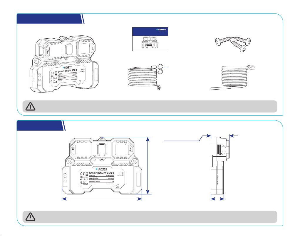
What’s In the Box?.............................................................................................................................................................1
Dimensions ........................................................................................................................................................................1
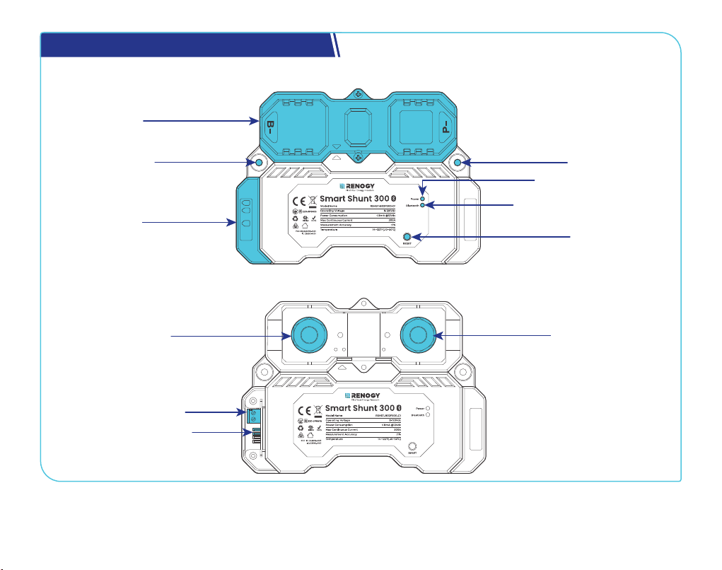
Get to Know Renogy Smart Shunt 300.......................................................................................................................... 2
Renogy Smart Shunt 300 System Setup ...................................................................................................................... 3
Required Tools & Accessories ........................................................................................................................................ 4
How to Size Bare Wires? .................................................................................................................................................. 5
Check System Voltage and Current .............................................................................................................................. 5
Step 1. Plan a Mounting Site ........................................................................................................................................... 6
Step 2. Wear Insulating Gloves....................................................................................................................................... 6
Step 3. Remove the Covers............................................................................................................................................. 7
Step 4. Connect the Shunt to the Main Battery Negative .......................................................................................... 8
Step 5. Connect the Shunt to the Device BAT- ............................................................................................................ 9
Step 6. Connect the Shunt to the Main Battery Positive.......................................................................................... 10
Step 7. Connect the Shunt to the Starter Battery Positive (Optional) ....................................................................11
Step 8. Install a Battery Temperature Sensor............................................................................................................ 12
Step 9. Mount the Shunt (Optional) ............................................................................................................................. 12
Step 10. Install the Covers............................................................................................................................................ 13
Step 11. Power On........................................................................................................................................................... 14
LED Indicators................................................................................................................................................................ 14
Bluetooth Pairing........................................................................................................................................................... 15
Energy Monitoring ......................................................................................................................................................... 16
Troubleshooting............................................................................................................................................................. 19
Important Safety Instructions ....................................................................................................................................20
Table of Contents

— 1 —
What’s In the Box?
Renogy Smart Shunt 300 × 1
Quick Guide × 1
B1/B2 Wires (1 m) (22 AWG) × 2 Temperature Sensor (1.5 m) × 1
VERSION A0
Smart Shunt 300
RENOGY
RSHST-B02P300-G1
QUICK GUIDE
Mounting Screws x 3
(1 extra)
ST4 x 18 mm
3/8 in
(M10)
B1
B2
T1
B1
B2
T1
Make sure that all accessories are complete and free of any signs of damage.
Dimensions
5.27 in (134 mm)
3.82 in
(97 mm)
1.22 in (31 mm)
0.87 in (22 mm)
B1
B2
T1
Dimension tolerance: ±0.2 in (0.5 mm)

— 2 —
Get to Know Renogy Smart Shunt 300
█Exterior
Upper Cover
Lower Cover
Mounting Hole Mounting Hole
Power LED Indicator
Bluetooth LED Indicator
RESET Button
B1
B2
T1
█Interior (with the covers removed)
B- Terminal (M10)
B1 and B2 Terminals
Battery Temperature
Sensor (T1) Port
P- Terminal (M10)

— 3 —
Renogy Smart Shunt 300 System Setup
Main Battery
Positive
+
- -
+
Temperature
B-
B1
P- Negative
Starter Battery (optional)
Loads / Chargers / Inverters
BAT-BAT+
DC-DC Battery Charger
-
+
B2
T1
You can connect the Smart Shunt 300 to a starter battery via the B2 port on demand.

— 4 —
Required Tools & Accessories
Insulating Gloves
Bare Wires × 2
Wrench
(11/16 in)
17 mm
17 mm
17 mm
Phillips
Screwdriver (#1) Wire stripper
Slotted
Screwdriver (1 mm)
Manual Hydraulic
Pliers
3/8 in Lugs
(M10 Ring Terminals) × 2
Heat Gun Heat Shrink Tubing
Prior to installing and configuring the shunt, prepare the recommended tools, components, and
accessories.
For how to size bare wires, refer to “How to Size Bare Wires?” in this manual.
For the connection methods and required tools for the main battery, starter battery, and
equipment terminal, please refer to the corresponding device user manual. The diagrams
provided within this manual are for illustrative purposes only.
For how to use Wire stripper, Heat Shrink Tubing, Manual Hydraulic Pliers, and Heat Gun to install
3/8 in Lugs (M10 Ring Terminals), visit renogy.com/support/downloads to check Smart Shunt
User Manual.

— 5 —
How to Size Bare Wires?
Select proper bare wires based on the ampacity in your power system. Refer to the table below for
copper cable ampacities with different gauge sizes.
Cable Gauge Size Ampacity Cable Gauge Size Ampacity
14 AWG (2.08 mm²) 35A 2 AWG (33.6 mm²) 190A
12 AWG (3.31 mm²) 40A 1 AWG (42.4 mm²) 220A
10 AWG (5.25 mm²) 55A 1/0 AWG (53.5 mm²) 260A
8 AWG (8.36 mm²) 80A 2/0 AWG (67.4 mm²) 300A
6 AWG (13.3 mm²) 105A 4/0 AWG (107 mm²) 405A
4 AWG (21.1 mm²) 140A
The above values are from the NEC Table 310.17 for copper cables rated at 194°F (90°C),
operating at an ambient temperature of no more than 86°F (30°C). Cables longer than 13 feet
(4000 mm) may require thicker gauge wires to prevent excessive voltage drop in undersized
wiring.
Check System Voltage and Current
Ensure the smart shunt operates within a power system with a maximum system voltage of 120V and a
continuous current of up to 300A. Exceeding these voltage and current limits may cause damage to the
shunt.
Risk of electric shock! Before installing the shunt, please turn off all devices within the system
and ensure there is no current flowing through the circuit.

— 6 —
Step 1. Plan a Mounting Site
Select a proper mounting site to ensure the shunt can be safely connected to the battery and other
necessary devices with the relevant cables. Install the shunt in a clean, cool, and dry location, free from
any accumulation of water, oil, or dirt. For optimal Bluetooth communication, avoid placing the smart
shunt near metal objects.
KEEP DRY FRAGILE VENTILATION
14°F to 122°F
-10°C to 50°C 0% to 95%
Enclosed space
Vent
Vent
Air
cross-flow
B1
B2
T1
Step 2. Wear Insulating Gloves
Insulating Gloves
B1
B2
T1

— 7 —
Step 3. Remove the Covers
█Remove the Upper Cover
B1
B2
T1
B1
B2
T1
█Remove the Lower Cover
B1
B2
T1
B1
B2
T1
Other manuals for Smart Shunt 300
1
This manual suits for next models
1
Table of contents
Other Renogy Power Supply manuals


