FEAS PS5U750130 User manual
Technische Daten können dem Produkt zugehörigen Datenblatt
entnommen werden.
Die Geräte vom Typ PS5U750130 sind anschlußfertige, ungeregelte
Netzgeräte.
Die Geräte sind für sinusförmige Eingangsspannungen ausgelegt.
Ausgang Potentialfrei nach VDE 0551
Tropentauglich - Gießharzvollverguß
Max. Gehäusetemperatur 105°C
Durch den Einsatz entsprechender Sicherungselemente sind die
Geräte vor Überlast bzw. Kurzschluß zu schützen.
Die grüne LED signalisiert den Betrieb des Gerätes.
Eine Wandmontage des Gerätes ist durch Verschraubung möglich.
Hierzu befindet sich eine Bohrschablone auf der Rückseite dieser
Betriebsanleitung.
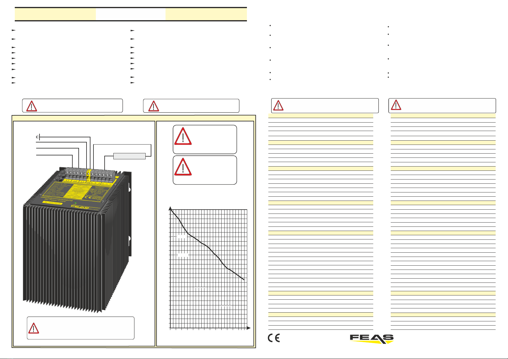
Anschlußschema / Cable arrangement Laststromdiagramme / Load-current diagram
When working with products which are in contact to dangerous electrical voltages, attention must
be payed to the relevant valid VDE / IEC / EN regulations. Especialy with refrence to the following
rules:
VDE 0100, VDE 0550 / 0551, VDE 0711, VDE 0860, IEC 664, IEC 742, IEC 570, IEC 65
In case of non-observance of this instructions, the unit or other equipment might be damaged
and no warranty or liability could be accepted.
When it is necessary to use tools with the units, components parts or subassemblies make it
sure, that the power is disconnected from the units and all electric charge which is stored in
components inside the unit are discharged.
Before opening the equipment disconnect the power cord or make sure, that the power is off
and the unit is currentless. It is only allowed to set components parts, subassemblies or units
into operation, if they are mounted in a shockproof housing. During the installation the unit
has to be currentless and the power has to be off.
Lifeparts (power cords and leads) which are connected to the units, components or
subassemblies have to be inspected for damage insulation or breaking. If a failure at the
power cord is detected the unit or the subassembly has to be put out of service at once. It is not
allowed to reopen the unit or the subassembly before replacing the damaged power cord.
It is the user’s responsibility to see that the marginal values of the equipment are not exeeded.
If it is not to distinguished for the not industrial ultimate user by the presented operating
instruction, which electrical data are the correct for the unit or the subassembly, a technical
adviser has always to be asked for technical information.
The observance of construction requirements and safety rules (VDE, IEC, employers liability
insurenance i.e.) is subject to the user/customer.
Beim Umgang mit Produkten, die mit elektrischen Spannungen in Berührung kommen, müssen die
gültigen VDE / IEC / EN Vorschriften beachtet werden. Besonders sei auf folgende Vorschriften
hingewiesen:
VDE 0100, VDE 0550 / 0551, VDE 0711, VDE 0860, IEC 664, IEC 742, IEC 570, IEC 65
Bei Nichtbeachtung der Bedienungsanleitung oder der Anschlußvorschrift, z.B. bei
Vertauschen der Anschlußklemmen, kann das Gerät oder die Anlage beschädigt werden und
der Betreiber verliert seinen möglichen Haftungsanspruch.
Werkzeuge dürfen an Geräten, Bauteilen oder Baugruppen nur benutzt werden, wenn
sicher g estel l t is t, daß d ie Geräte von der Versor g ungssp annung getre nnt
sind und elektrische Ladungen die in im Gerät befindlichen Bauteile gespeichert
sind, vorher entladen wurden.
Vor dem Öffnen des Gerätes den Netzstecker ziehen oder sicherstellen, daß das Gerät
stromlos ist. Bauteile, Baugruppen oder Geräte dürfen nur in Betrieb genommen werden,
wenn sie vorher in ein berührungssicheres Gehäuse eingebaut wurden. Während des
Einbaus müssen sie stromlos sein.
Spannungsführende Kabel oder Leitungen mit denen das Gerät, das Bauteil oder die
Baugruppe verbunden sind müssen stets auf Isolationsfehler oder Bruchstellen untersucht
werden. Bei Feststellen eines Fehlers in der Zuleitung muß das Gerät unverzüglich aus dem
Verkehr genommen werden, bis die defekte Leitung ausgewechselt worden ist.
Der Anwender hat dafür Sorge zu tragen, daß die angegebenen Gerätedaten nicht
überschritten werden.
Wenn aus den vorgelegten Beschreibungen für den Anwender oder Erwerber nicht eindeutig
hervorgeht, welche Kennwerte für ein Gerät oder Bauteil gelten, so muß stets ein Fachmann
um Auskunft ersucht werden.
Im übrigen unterliegt die Einhaltung von Bau- und Sicherheitsvorschriften aller Art ( VDE, TÜV,
Berufsgenossenschaften ) dem Anwender / Käufer.
Allgemeine Sicherheitsvorschriften : General safety rules :
Technical data can be taken by the relevant product affilated data-
sheet.
The power supply units of the series PS5U750130 are ready for
installation on delivery.
The units are constructed for sinus-oidal input voltage.
Output separated according to VDE 0551
Suitable for the tropics - Epoxy resin casted
Max. case-temperature 105°C
The units should be protected by the right fuses against overload or
short circuit by the user.
The correct operation of the unit is indicated by the green LED.
The appliance can be screwed at the wall. A drill-pattern is shown on
the rear of this instruction.
Eingangsgrößen
Frequenz
Eingangsspannungstoleranz
Eingangsstrom
Verbrauch
Ausgangsgrößen
Ausgangsspannung U
Einstellbereich
Ausgangsstrom I
Einsatz der Strombegrenzung
Restwelligkeit (100Hz)
Betriebsdaten
Einschaltdauer (ED)
Arbeitstemperatur
Temperaturkoeffizient
Lagertemperaturbereich
Wirkungsgrad
Leistungsabweichung bei Temp.
Kühlung
Schutzeinrichtungen
Vorsicherung
Ausgangssicherung
Überlastschutz
Netzausfallüberbrückung
MTBF
Sicherheitsdaten
Prüfspannung Trafo
Hochspannungsfestigkeit
Luft- und Kriechstrecken
Funkenentstörgrad
Schutzklasse
Umgebungsfeuchte
Schutzart Gehäuse
Schutzart Klemmen
Rüttelfestigkeit
Angewandte Bauvorschriften
gemäß VDE
IEC
EN
CSA / UL
Mechanik
Befestigung
Maße (BxHxT)
Gewicht
Nenn
Eingangsspannung Siehe Gehäuseaufdruck des Gerätes
45 - 66 Hz
-20% bis +15%
max. 3,8 Amp. ohne Inrush
max. 800VA
130Volt DC
-
-
Siehe Gehäuseaufdruck des Gerätes
-
-
-
max. 6,0Amp.
< 2%
100%
- 30°C bis +70°C
< 500ppm / K
-30°C...+105°C
ca. 90%
natürliche Konvektion (S)
in Höhe des Ausgangstroms absichern
20 mSek. typ.
>400.000 h
5 kVac gemäß VDE 0551
Eingang / Ausgang 3,75 kVac
nach VDE 0806 / IEC 380
Primärkreis - Sekundärkreis >8mm
nach VDE 0110
< K nach VDE 0875 und VDE 0877
Klasse 1 mit PE-Anschluss (EN 60950)
95% relative Feuchte im Jahresdurchschnitt,
Betauung möglich - tropentauglich
IP 65
IP 20
>30g bei 33Hz in X,,Y und Z,
nach IEC 68 und DIN 41640
VDE 0100, 0110, 0113, 0551, 0160/W2, 0806
IEC 380, IEC 60950, IEC61000-6-1-2
EN 60950, EN50082-1, EN61000-6-1-2
CSA-C 22.2 / UL60950, UL508, UL1950
Aufschraubbar
171mm x 224mm x 103mm
ca. 17,25kg
Nenn
max. 3,8 Amp. without Inrush
130Volt DC
6,0Amp.
171mm x 224mm x 103mm
approx. 17,25kg
-
-
see face plate
-
-
-
EN 60950, EN50082-1, EN61000-6-1-2
Input data
Input voltage
Input current
Consumption
Output data
Output voltage U
Rang of adjustment
Output current
Start of current limiting
Residual ripple (100Hz)
Operating data
Starting time
Operating temperature
Temperature coefficient
Efficiency
Derating
Cooling
Safety devices
Output fuse
Overload protection
Hold-up time
MTBF
Safety data
Test voltage transformer
High-voltage resistance
Air gaps and leakage paths
Degree of EMI suppression
Protection class
Ambient humidity
Protective class enclosure
Protective class terminals
Vibration proof
Applied construction regulations
according to VDE
IEC
EN
CSA / UL
Mechanics
Mounting
Dimensions (WxHxD)
Weight
nomnal
see face plate
45 - 66 Hz
-20% to +15%
max. 800 VA
< 2%
100%
-30°C to +70°C
< 500 ppm / K
-30°C...+105°C
ca. 90%
selfcooling (S)
In dependency to the output current
20 msec. typical
> 400.000 h
5 kVac in accordance to VDE 0551
Primary circuit - secondary circuit 3,75 kVac
acc. to VDE 0806 / IEC 380
Primary circuit - secondary circuit >8mm
acc. to VDE 0110
< K in accordance to VDE 0875 and VDE 0877
Class 1 with PE-Connection (EN 60950)
95% rel. humidity, yearly average dewing
allowed for use in tropical ambient
IP 65
IP 20
>30g at 33Hz in X, Y and Z,
acc. to IEC 68 and DIN 41640
VDE 0100, 0110, 0113, 0551, 0160/W2, 0806
IEC 380, IEC 60950, IEC61000-6-1-2
CSA-C 22.2 / UL60950, UL508, UL1950
With screws
Frequency
Input voltage tolerance
Storage temperature range
Fuse recomended for input
145,0
143,5
140,0
138,0
136,5
135,0
134,0
133,0
132,0
131,0
130,0
128,0
126,0
124,0
122,0
120,0
118,0
36,5
36,0
35,5
35,0
34,5
34,0
33,5
33,0
32,5
32,0
0 0,4 0,8 1,2 1,6 2,0 2,4 2,8 3,2 3,8
U - I Verlauf bei 480V Eingangsspannung
U
I
U - I Diagram with 480V Inputvoltage
Ausgangsspannung - Outputvoltage in VDC
Ausgangsstrom - Outputcurrent in Ampère
4,6 5,4 6,0 6,6
134,0VDC
130,0VDC
Betriebsanleitung
Bitte sorgfältig beachten!
Operating instructions
Please observe carefully!
PS5U750130
- konform GmbH
Postfach 1521
D - 22905 AHRENSBURG
Telefon: 04102 - 42082
Telefax: 04102 - 40930
www.feas.de
©2017 ®Stand: 16.08.2017
Induktive Verbraucher (Schütze, Motoren, Magnet-ventile, etc.) die
nicht ordnungsmäßig nach den relevanten Richtlinien entstört sind
(Varistoren, RC-Glieder, etc.), können zur Störung der
Netzteilregelung führen.
Inductive consumers (contactors, motors, solenoid valves etc.)
which have not been correctly interference-suppressed in
accordance to the relevant guidelines (varistors, RC elements, etc.)
may cause power supply regulation to malfunction.
Kurzschluß und Überlast am
Ausgang sind zu vermeiden! Avoid short-circuit or
overload at the output!
Anschlußschema / Cable arrangement
3x480 V~
+
-
L1
L2
L3
PE
Netzspannung
line-voltage Verbraucher
consumer
z.B. PSU75024
i.e. PSU75024
ACHTUNG!
Bei Stromentnahme von mehr als 8A muss der Strom gleichmäßig
über alle drei PLUS- und MINUS-Ausgangsklemmen verteilt werden.
ATTENTION!
If the output current exceeds 8A, the output current have to be
distributed equally over the three PLUS and MINUS output terminals.
In Abhängigkeit zur
Umgebungstemperaur
und Lastentnahme sollte
gegebenenfalls Fremd-
belüftung eingesetzt
werden.
Depending on the
ambient temperature
and drawn load, external
ventilation should be
used.
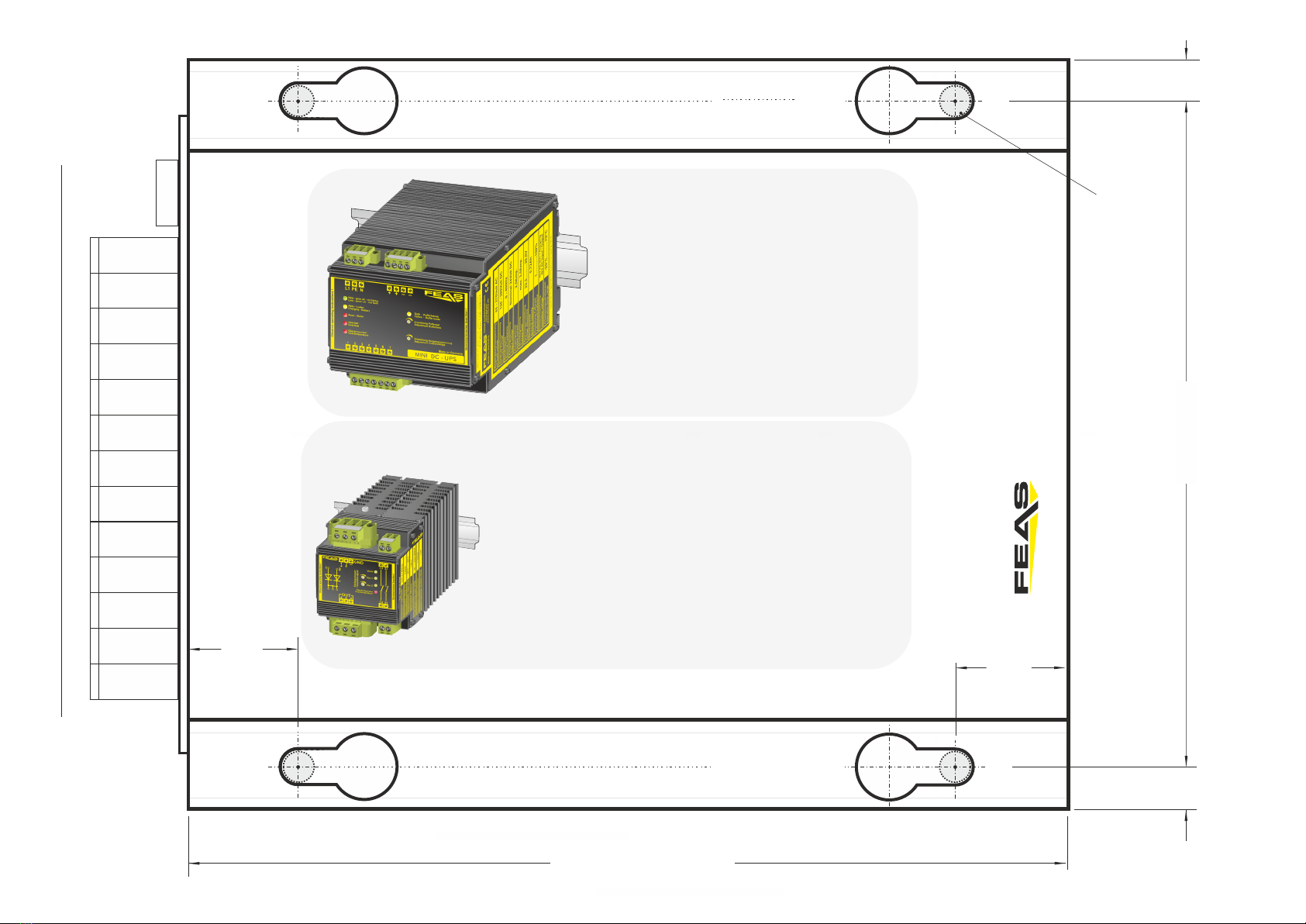
200 mm (PSU750-K)
151,5
9,5 9,5
25,0
25,0
Geeignet für M8 Schrauben
Suitable for M8 screws
Maße Rückseite - Dimensions backside
GmbH
Postfach 1521
D - 22905 AHRENSBURG
Telefon: 04102 - 42082
Telefax: 04102 - 40930
www.feas.de
©2017 ®
Stand: 16.08.2017
RZM122-80M Redundanzmodul
Art.Nr.: 52007
ŸErhöhen Sie Ihre Anlagensicherheit nach (n+1)
oder (1+1) Prinzip
ŸLED Statusanzeige
ŸRelaismeldung für Netzausfall und Übertemperatur
ŸEinstellbare Fehlerwertgrenze
ŸIntegrierter Kühlkörper
ŸThermischer Überlastschutz
ŸVerpolungsschutz
ŸEinfache Montage auf DIN-Schiene
ŸEMV und Niederspannungsrichtlinienkonform
ŸSicherheit nach VDE, EN, UL, CSA
Technische Daten:
Spannungsbereich: 40-120 VDC
Eingangsstrom: 2x 40 A
Ausgangsstrom: 1x 80 A
Arbeitstemperatur: -40°C / +80°C
Montage: auf Hutschiene nach DIN 46277
Abmaße (BxHxT): 73,0 x 118,0 x 118,0 mm
Gewicht: 1,28 kg
ŸImprove your system security by (n +1) or (1 +1) Principle
ŸStatus indication by LED
ŸMessage relay for power failure and overheating
ŸAdjustable error value limit
ŸIntegrated heat sink
ŸThermal overload protection
ŸReverse polarity protection
ŸSimple mounting on rail acc. to DIN 46277
ŸConforms to EMC and low voltage directive
ŸSafety acc. to VDE, EN, UL, CSA
Technical data:
Voltage range: 40-120 VDC
Input current: 2x 40 A
Output current: 1x 80 A
Operating temperature range: -40°C / +80°C
Mounting: on rails acc. to DIN 46277
Dimensions (WxHxD): 73.0 x 118.0 x 118.0 mm
Weight: 1.28 kg
Werbung/Advertising
LDR30MH24
Mini DC-USV für die Hutschiene
Ÿ3 in 1, vereint Schaltnetzteil, Ladekontrolleinheit und Akku in
einem sehr kompakten Gehäuse
ŸPufferung eines Verbrauchers bei Netzausfall
ŸPufferzeit begrenzbar (1-20 Minuten und unbegrenzt)
ŸIm Pufferbetrieb manuell abschaltbar, “Schlafenlegen”
ŸIntegrierter NiMH Akkumulator mit 0,72 Ah (austauschbar)
ŸMikroprozessorgesteuerte Akkumulator-Überwachung und
Ladeanzeige
ŸLED-Anzeigen für Netzausfall, Überlast und Übertemperatur
ŸRelais-Meldung von Netzausfall, Übertemperatur, Akku-
Defekt und Akkuspannung kritisch
ŸBoostfunktion: 150% Iout bis zu 30s
ŸKurzschlussfest, überlast- und leerlaufsicher
ŸAusgang potentialfrei nach VDE 0551
ŸSicherheit nach VDE, EN, UL und CSA
Other FEAS Power Supply manuals


