SDMO NEO 2000 Operating instructions

MANUEL D’UTILISATION ET
D’ENTRETIEN DES GROUPES
ELECTROGENES
(notice originale)
USER AND MAINTENANCE
MANUAL FOR GENERATING
SETS
MANUAL DE USO Y
MANTENIMIENTO DE LOS
GRUPOS ELECTRÓGENOS
HANDBUCH ZUR
BEDIENUNG UND
WARTUNG VON
STROMERZEUGERN
MANUALE D'USO E
MANUTENZIONE DEI GRUPPI
ELETTROGENII
MANUAL DE UTILIZAÇÃO E
DE MANUTENÇÃO DOS
GRUPOS ELECTROGÉNEOS
GEBRUIKS- EN
ONDERHOUDSHANDLEIDING
VOOR STROOMAGGREGATEN
PУКОВОДСТВО ПО
ЭКСПЛУАТАЦИИ И
ТЕХНИЧЕСКОМУ
ОБСЛУЖИВАНИЮ
ГЕНЕРАТОРНЫХ УСТАНОВОК
ANVÄNDAR- OCH
UNDERHÅLLSMANUAL FÖR
GENERATORAGGREGATEN
GENERAATTORI
KONEISTOJEN KÄYTTÖ-JA
HUOLTO-OHJEKIRJA
BRUGER- OG
VEDLIGEHOLDELSESMANUAL
FOR
GENERATORAGGREGATER
ΕΓΧΕΙΡΙ∆ΙΟ ΧΡΗΣΗΣ ΚΑΙ
ΣΥΝΤΗΡΗΣΗΣ ΤΩΝ
ΗΛΕΚΤΡΟΓΕΝΝΗΤΡΙΩΝ
NÁVOD K POUŽITÍ
ELEKTROGENERÁTORŮ
GENERAATORAGREGAATIDE
KASUTUS- JA
HOOLDUSJUHEND
ĢENERATORAGREGĀTU
LIETOŠANAS UN
UZTURĒŠANAS
INSTRUKCIJA
GENERATORIŲNAUDOJIMO
IR TECHNINIO
APTARNAVIMO
INSTRUKCIJOS
ÁRAMTERMELŐEGYSÉGEK
FELHASZNÁLÓI ÉS
KARBANTARTÁSI
KÉZIKÖNYVE INSTRUKCJA OBSŁUGI I
KONSERWACJI ZESPOŁÓW
PRĄDOTWÓRCZYCH
NÁVOD NA POUŽÍVANIE A
ÚDRŽBU
ELEKTROGENERÁTOROV PRIROČNIK ZA UPORABO
IN VZDRŽEVANJE
ELEKTRIČNIH AGREGATOV
33522170601_2_1
NEO 2000

6
23
7
10
5
4
A
A
B C
1
8
9
11 13
12

3
4
BC
1
2
OFF
ON
1
2

D E
1
2
1
2

Contents
1. Preface
2. General description
3. Preparation before use
4. Using the generating set
5. Safety features
6. Maintenance schedule
7. Maintenance procedures
8. Storing the generating set
9. Troubleshooting
10. Specifications
11. Cable sizes
12. EC Declaration of conformity
1. Preface
1.1. Recommendations
Warning
Read this manual carefully before use.
The safety advice and the usage and maintenance instructions for the generating set must always
be strictly adhered to.
The information contained in this manual is taken from technical data available at the time of print. In line with our policy of continually
improving the quality of our products, this information may be amended without warning.
1.2. Pictograms and plates on the generating sets and what they mean
Danger
Danger:
risk of electric shock
Earth
Danger: risk of burns
Danger: the generating set is
supplied without oil.
Before starting the generating
set always check the oil level.
1 2 3
1 - Warning: refer to the documentation accompanying the generating set.
2 - Warning: emission of toxic exhaust gases. Do not use in a confined or poorly
ventilated area.
3 - Stop the motor before filling with fuel.
A = Generating set model
B = Generating set output
C = Voltage
D = Amperage
E = Current frequency
F = Power factor
Example of an identification plate
G = Protection rating
H = Generating set noise output
I = Generating set weight
J = Reference Standard
K = Serial number
1.3. Instructions and safety regulations
Danger
Do not run the generating set without having put back the protective covers and closed the access doors.
Never take the protective covers off or open the access doors if the generating set is running.
1.3.1 Warnings
You are likely to encounter several warning symbols in this manual.
Danger
This symbol indicates a definite risk to a person's health and life. Failure to follow the corresponding
instruction poses serious risks to the health and life of those concerned.
Warning
This symbol draws attention to the potential risk to a person's health and life. Failure to follow the corresponding
instruction may pose serious risks to the health and life of those concerned.
Important
This symbol indicates a dangerous situation if the warning is not heeded.
Failure to follow this instruction could result in less serious injury or damage.

1.3.2 General advice
On taking delivery of the generating set, check that it is complete and not damaged in any way. A generating set should be handled
gently and brusque movements should be avoided. Ensure that the place where it is to be stored or used is carefully prepared
beforehand.
Warning
Before use:
- make sure you know how to stop the generating set in the event of an emergency,
- make sure you completely understand all the controls and operations.
For reasons of safety, the maintenance intervals must be respected (see Maintenance table). Never carry out repairs or maintenance
procedures without the necessary experience and/or tools.
Never let other people use the generating set without having given them all the necessary instructions beforehand.
Never let children touch the generating set, even when it is not in operation. Do not operate the generating set near animals (as it could
cause them to panic or frighten them).
Never start the engine without an air filter or exhaust.
Never invert the positive and negative terminals on the battery (if fitted) when fitting them as this could cause serious damage to the
electrical equipment.
Never cover the generating set with any type of material while it is in operation or just after it has been turned off. Wait until the motor is
cold.
Never coat the generating set with oil, even to protect it from corrosion; preservative oils are flammable and can be dangerous if
inhaled.
In all cases, respect the local regulations currently in place concerning the use of generating sets.
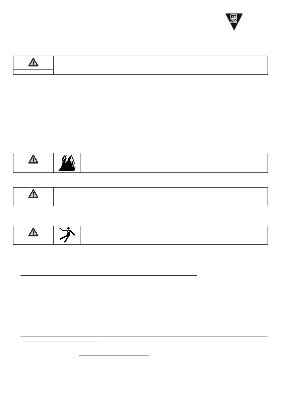
1.3.3 Safety guidelines to prevent fire
Danger
Never operate the generating set in areas containing flammable products (risk of sparks).
Keep all flammable products (petrol, oil, fabric etc.) out of the way when the unit is in
operation. Never cover the generating set with any type of material while it is in operation
or just after it has been turned off: always wait until the engine cools down.
1.3.4 Safety guidelines against burns
Warning
Never touch the engine or the silencer while the generating set is in operation, or when it has just stopped.
Hot oil burns; avoid contact with the skin. Before carrying out any operation, check that the system is no longer pressurised. Never start
or run the engine if the oil filler cap is off (oil may splash out).
1.3.5 Safety guidelines to prevent electrocution
Danger
The generating sets supply electrical current when in operation: risk of electrocution.
Never touch stripped cables or disconnected connectors. Never handle a generating set with wet hands or feet. Never expose the
equipment to liquid splashes or rainfall, and do not place it on wet ground.
Always keep electric cables and connections in good condition. Never use equipment in poor condition: risk of electrocution or damage
to the equipment.
Specific protective measures to follow in accordance with the operating conditions.
1 – If the generating set is not equipped with an integrated differential protection device at delivery
In the case of occasional use of one or many mobile or rotating devices, the earthing of the generating set is not necessary, but the
following installation rules must be complied with:
a) The grounds of the equipment connected to the outlets of the generating set must be interconnected with the ground of the set
by a protection conductor. This equipotentiality is performed if all the connecting cables of class I equipment are fitted with a PE
protection conductor (GREEN and YELLOW) correctly connected to their patches to the generating set (this protection conductor is
not necessary for equipment of class II protection). The good condition of the cables and the ground connections is an essential
element to guarantee protection against electric shocks, therefore the usage of rubber sheathed cables is strongly recommended,
flexible and strong, in compliance with standard IEC 60245-4 Comply with the cable lengths indicated in the table of the paragraph
“Cable sizes”.
b) Each channel (electrical cable) originating from the generating set must be protected by a complementary differential device calibrated
at 30mA, set up before each outlet less than 1 m from the set, and protected against external influences to which it could be subjected.
2 – If the generating set is equipped with an integrated differential protection device at delivery (with the alternator ground connected to
the earth terminal of the generating set)
In the case of occasional use of one or many mobile or rotating devices, the earthing of the generating set is not necessary, but
the ground connection rules listed in point a) of paragraph 1 above must be complied with.
In the case of the supply of a temporary or semi-permanent station (site, show, fairs,.), connect the ground of the generating set to
the earth and follow the rules listed in point a) of paragraph 1 above.

In the case of the emergency re-supply of a fixed installation, the connection of the generating set to the ground of the installation
to re-supply and the electrical connection must be performed by a qualified electrician, in compliance with the regulation
applicable on the installation site. Do not connect the generating set directly to other power sources (e.g.: public distribution
network); install a power inverter.
Mobile applications (example: generating set installed in a moving vehicle)
If earthing is not possible, the grounds of the vehicle and of the equipment connected to the outlets of the generating set must be
interconnected with the ground of the generating set by a protection conductor, in compliance with the ground connection rules listed at
point a) of paragraph 1 above.
The protection against electric shocks is performed by circuit breakers provided specially for the generating set: if necessary, replace
them with circuit breakers having the same ratings and characteristics.
1.3.6 Danger of moving parts
Danger
Never go near a moving part that is in operation if you have loose clothing or long hair that
is not enclosed in a protective hair net.
Do not try to stop, slow down or impede a moving part when it is in operation.
1.3.7 Safety guidelines for exhaust gases
Danger
The carbon monoxide present in the exhaust gas may lead to death by inhalation if the
concentration levels in the atmosphere are too high.
Always use the generating set in a well ventilated area where the gases cannot
accumulate.
For safety reasons and for correct operation of the generating set, correct ventilation is essential (risk of intoxication, engine
overheating and accidents involving, or damage to, the surrounding equipment and property). If it is necessary to operate it inside a
building, the exhaust gases must be evacuated outside and adequate ventilation must be provided so that any people or animals
present are not affected.
1.3.8 Operating conditions
The stated outputs of the generating sets are obtained under the reference conditions outlined in ISO 8528-1(2005):
9Total barometric pressure: 100 Kpa - Air ambient temperature: 25°C (298K) - Relative humidity: 30%
Generating set performance is reduced by approximately 4% for every additional 10° C and/or approximately 1% for every additional
100m in altitude.
1.3.9 Capacity of the generating set (overload)
Never exceed the rated load of the generating set (in Amps and/or Watts) when it is running continuously.
Before connecting and operating the generating set, calculate the electrical power required by the electric appliances (in Watts). This
electrical power rating is usually found on the manufacturer's plate on bulbs, electrical appliances, motors etc. The sum total of power
required by these appliances should not exceed the nominal power rating of the generating set.
1.3.10 Protecting the environment
Drain the engine oil into a designated container: never drain or discard engine oil onto the ground.
As far as possible, avoid sound reverberating through walls or buildings (the noise will be amplified).
If the generating set is used in wooded, bushy or uncultivated areas and if the exhaust silencer is not fitted with a spark arrester, clear
any vegetation away from the area and take care that the sparks do not cause a fire.
1.3.11 Filling with fuel
Danger
The fuel is highly flammable and its vapours are combustible.
Filling should be carried out with the engine turned off. Smoking, using a naked flame or
producing sparks are forbidden while the fuel tank is being filled.
All traces of fuel should be wiped off with a clean cloth.
Storage and handling of petroleum products must be carried out in accordance with the law. Close the fuel tap (if fitted) each time the
tank has been filled. Never top up fuel when the generating set is in operation or hot.
Always place the generating set on a flat, level and horizontal surface to avoid fuel spilling onto the motor. Fill the tank with a funnel
taking care not to spill the fuel, then screw the plug back onto the fuel tank.
1.3.12 Safety guidelines for handling batteries
Danger
Never leave the battery close to a flame or fire.
Use only insulated tools.
Never use sulphuric acid or acid water to top up the electrolyte level.

2. General description
Figure A
Earth connection (no.1) MAX / ECO Mode (no. 9)
Inspection cover (no.2) Tank pressurisation pump (no.10)
Fuel tap (no.3) Indicator lamps (no.11)
Fuel tank aeration pointer (no.4) A. Operating light
Fuel tank cap (no.5) A. Overload indicator
Choke (no.6) C. Oil safety indicator
Recoil starter (no.7) Spark plug access cover (no.12)
Electrical socket (no.8) Muffler (no.13)
Figure B
Inspection trap cover (no.1) Oil filler and drain plug (no.2)
Maximum oil filling level
Figure C
Fuel tank aeration pointer O
ON
N/
/O
OF
FF
F (no. 1) Fuel filter (no. 4)
Tank pressurisation pump (no.2)
Fuel strainer (no.3)
Maximum fuel filling level
Figure D
Air filter cover (no.1) Filter element (no.2)
Filter element cleaning
Figure E
Spark plug access cover (no.1) Spark plug (no. 2)
3. Preparation before use
3.1. Positioning the generating set for operation
Choose a site that is clean, well ventilated and sheltered from bad weather.
Place the generating set on a flat, horizontal surface which is firm enough to prevent the set sinking down (under no circumstances
should the set tilt in any direction by more than 10°).
Store the additional supplies of oil and fuel within close proximity, whilst maintaining a certain distance for safety.
3.2. Earthing the generating set
Danger
The generating sets supply electrical current when in operation: risk of electrocution.
Connect the generating set to the ground at each use.
To connect the set to the ground: Attach a 10 mm2copper wire to the set’s earth connection and to a galvanised steel earthing rod
driven 1 meter into the ground.
3.3. Checking the oil level
Important
Before starting the generating set, always check the level of engine oil.
Supplement it with the recommended oil (see § Specifications) with the help of a funnel, up to the upper limit of
the gauge.
nOpen the inspection cover (fig. A – no. 2).
oUnscrew the oil filler plug (fig. B – no. 2).
pCheck the oil level.
qIf necessary supplement it.
rScrew back the filler plug.
sWipe any excess oil with a clean cloth.
tClose the inspection cover (fig. A – no. 2).

3.4. Checking the fuel level
nClose the fuel tap (fig. A – no.3).
oSet the fuel tank aeration pointer to O
ON
N position (fig. A – no. 4 & fig. C – no. 1).
pUnscrew the fuel tank cap (fig. A – no. 5).
qCheck the fuel level. Taking care not to spill the fuel, use a funnel to fill the tank up to its filling limit.
rScrew the fuel filler cap back onto the fuel tank.
sSet the fuel tank aeration pointer of the fuel tank to O
OF
FF
F
position (fig. C – No. 1).
3.5. Checking the air filter
Important
Before starting the generating set, check the air filter.
nOpen the inspection cover (fig. A – no. 2)
oUnlock the air filter and remove its cover (fig. D – no. 1).
pCheck the condition of filter element, if necessary clean it (see § Cleaning of air filter).
4. Using the generating set
Warning
Before use:
- make sure you know how to stop the generating set in the event of an emergency,
- make sure you completely understand all the controls and operations.
To stop the generating set urgently, place the engine switch on "OFF" or "О".
4.1. Starting procedure
To restart the generating set after a stoppage of more than 10min or when the fuel level has come down by at least half the tank level,
pressurise the fuel tank by using the pressurisation pump (see § Usage of tank pressurisation pump).
nCheck that the generating set is properly earthed (fig. A- no. 1 & see § Earthing the generating set).
oSet the fuel tank aeration pointer to O
ON
N position (fig. A – no. 4 & fig. C – no. 1).
pOpen the fuel tap (fig. A – no.3).
qSet the choke (fig. A – no.6) to « » position.
N.B: Do not use the starter when the engine is hot or when the atmospheric temperature is high.
rGently pull the recoil starter once (fig. A – no. 7) until resistance encountered, allow it to return back slowly.
sThen, pull the recoil starter quickly and powerfully until the engine starts-up.
tSlowly place the choke in « » position and wait until the engine temperature begins to rise before using the generating set.
4.1.1 Usage of tank pressurisation pump
The fuel tank must be pressurised with the help of a pump:
- after a shut down of the generating set for over 10 minutes,
- when the fuel level has dropped by at least half of the tank level.
Important
Never use the fuel tank pressurisation pump when the fuel level is more than half of the tank level
(generating set deterioration risk).
nSet the fuel tank aeration pointer to O
OF
FF
F position (fig. C – no. 1).
oActivate the tank pressurisation pump several times (fig. C – no. 2).
pWait for 20 seconds.
qStart the generating set by placing the fuel tank aeration pointer in O
OF
FF
F position.
rSet the fuel tank aeration slide in O
ON
N position (fig. C – no. 1).
Danger
The fuel must be refilled when the engine is off and according to safety guidelines (see
§ Filling with fuel).
Before opening the fuel tank cap, always set the fuel tank aeration pointer to the O
ON
N position.
Important
Use only clean fuel without any water.
Do not overfill the tank (there should not be any fuel in the filler neck). After the tank has been filled, always
ensure that the filler plug is properly tightened. If any fuel has been spilt, make sure that it has dried and that any
vapours have cleared before starting up the generating set.

4.2. Operation
When the generating set is warm and the running speed has stabilised (after approximately 3 minutes):
nCheck that the operating light is turned on (fig. A – no. 11, A).
oActivate the “MAX” or “ECO” mode (fig. A – no. 9).
pConnect the devices to the generating set sockets (fig. A – no. 8).
In case of overload or short-circuit, the operating light (fig. A – no. 11, A) switches–off and the overload indicator (fig. A – no. 11, B)
glows: Stop the generating set and eliminate the overload.
4.2.1 MAX-ECO mode Fig. A – no. 9
MAX
When the button is in the “MAX” position, the generating set can react to a
large inrush current (at no load, it rotates at 5000 rpm).
ECO
The “ECO” position is useful for smaller loads. Between 0 and 400W, the
generating set consumes less and is quieter (at no load, it rotates at
4000 rpm).
From a load demand of 400W, the operating speed is the same whatever the position of the MAX-ECO button.
4.3. Switching off
nShut down and disconnect the devices.
oAllow the engine to run idle for 1 or 2 min.
pSet the fuel tank aeration pointer to O
OF
FF
F position (fig. A – no. 4 & fig. C – no. 1).
qClose the fuel tap (fig. A – no.3).
The generator set comes to a stop.
5. Safety features
5.1. Oil cut-out
If there is no oil in the engine sump or if the oil pressure is low, the oil safety mechanism automatically stops the engine to prevent any
damage.
If this occurs, check the engine oil level and top it up if necessary before looking for any other cause of the problem.
5.2. Circuit breaker
The set's electrical circuit is protected by one or more magnetothermal, differential or thermal cut-out switches. In the event of an
overload and/or short circuit, the supply of electrical energy may be cut.
If necessary, replace the circuit breakers in the generating set with circuit breakers with identical nominal ratings and specifications.
Warning
Always ensure suitable ventilation for the generating set.
Even after shut down, the engine continues to dissipate heat.

6. Maintenance schedule
6.1. Reminder of use
The maintenance operations to be carried out are described in the maintenance schedule. The interval for this is supplied as a guide
and for generating sets operating with fuel and oil which conform to the specifications given in this manual.
If the generating set is used under extreme conditions, the interval between the maintenance operations must be shortened.
6.2. Maintenance table
Component
Operations to be carried
out on reaching the 1st
due date
With each usage
Every month
or
Every
10 hours
Every 3 months
or
Every
50 hours
Every year
or
Every
300 hours
Generating set Cleaning •
Check the level •
Engine oil Renew
•
Fuel strainer Cleaning •
Checking •
Air filter Cleaning •
Spark plug Check and clean •
Valves* Checking* •
* These operations must be entrusted to one of our agents
If used occasionally only, drain-out the engine oil at least once a year.
7. Maintenance procedures
Warning
Before carrying out any maintenance operation:
- switch off the generating set.
- disconnect the cap(s) of the spark plug(s) and disconnect the starter battery (if fitted).
Only use original parts or equivalent parts: risk of damage to the generating set.
7.1. Checking bolts, nuts and screws
To prevent faults or breakdowns, carefully check all the nuts, bolts and screws on a daily basis.
nInspect the entire generating set before and after each use.
oTighten any loose nuts or bolts.
7.2. Renewing the engine oil
Adhere to the environment protection guidelines (see §Protecting the environment) and drain the oil into an appropriate
container.
nOpen the inspection cover (fig. A – ,o. 2).
oWith the engine still warm, remove the filler and draining plug (fig. B – no. 2).
pGently tilt the generating set to empty the oil into the appropriate container.
qAfter complete draining, fill it with the recommended oil (see § Specifications), check the level.
rRefit the filler and draining plug (fig. B – no. 2).
sCheck for oil leakage.
tWipe any oil traces with a clean cloth.
uClose the inspection cover.

7.3. Cleaning the fuel strainer
Danger
Do not smoke, or create sparks. Keep away from open flames. Check for absence of
leakage, wipe out any fuel traces and ensure that the vapours are cleared-up before starting
the generating set.
nClose the fuel tap (fig. A – no.3)
oRemove the fuel tank cap and the strainer (fig. C – no.2).
pWith a low pressure dry air gun, from outside blow air inwards on to the strainer.
qRinse with clean fuel.
rPut back the strainer in place and carefully screw back the fuel tank cap.
7.4. Replacing the fuel filter
Danger
Do not smoke, or bring naked flames or generate sparks nearby. Check that there are no
leaks, wipe off any trace of fuel and ensure that the vapours have dissipated before
restarting the generating set.
nClose the fuel tap (fig. A – no. 3).
oObserve the direction of fitting for the filter.
pRelease the fuel filter from its support bracket (fig. C – no. 4).
qRemove the fuel pipes on either side of the filter and use a suitable container to collect the fuel.
rFit a new filter, observing the direction of fitting.
sOpen the fuel tap and check that there are no leaks.
7.5. Cleaning the air filter
Important
Never use petrol or flammable solvents for cleaning the air filter element (risk of fire or explosion).
nRemove the inspection cover (fig. A – no. 2).
oRemove the filter cover (fig. D – no. 1).
pRemove the filter element (fig. D – no. 2) and check the type of clogging:
Dry clogging:
nUse a low-pressure dry compressed air gun to blow from the inside of the filter element out, moving from the top to the bottom
until there is no more dust.
oCheck the condition of the filter element: replace it if it is at all damaged.
pRefit the filter element and its cover.
qPut back the inspection cover.
Moist/oily clogging:
nReplace the filter element.
oRefit the filter element and its cover.
pPut back the inspection cover.
7.6. Checking the spark plug
nOpen the spark plug access cover (diag. E - no. 1), and fit the spark plug with the help of a plug spanner.
oCheck the condition of the spark plug (diag. E - no. 1) :
If the electrodes are worn or if the insulation is split or flaking: Otherwise:
pReplace the spark plug.
qFit a new spark plug in position and tighten it by hand to
avoid damaging the threads.
rUse a spark plug spanner to tighten the spark plug by 1/2
turn after it is seated to compress the washer.
pClean the spark plug with a metal brush.
qWith a feeler gauge, check the electrode gap "X": it must be
between 0.7 and 0.8 mm inclusive.
rCheck the condition of the washer.
sFit the spark plug in position and tighten it by hand to avoid
damaging the threads.
tUse a spark plug spanner to tighten it by 1/8-1/4 turn after it
is seated to compress the washer.

7.7. Cleaning the generating set
Important
Cleaning with a water jet is not recommended.
Cleaning with high pressure cleaning equipment is forbidden.
nRemove all dust and debris from around the exhaust
oClean the generating set, particularly the alternator and engine air inlets and outlets, using a cloth and brush.
pCheck the general condition of the generating set and replace any faulty parts
8. Storing the generating set
In case of prolonged non-usage of the generating set, carry out storage operations in accordance with the guidelines given below.
nRemove the carburetor draining screw and drain the fuel completely into an appropriate container.
oRun the engine till it stops due to lack of fuel.
pClose the fuel tank aeration pointer (fig. C – no. 1, OFF) and the fuel valve (fig. A – no. 3).
qRenew the engine oil.
rRemove the spark plug (fig. E – no. 2) and pour around 15ml of engine oil into the cylinder through the spark plug opening.
sRefit the spark plug.
tPull the recoil starter handle 3 to 4 times (fig. A – no. 7) to completely drain-out the carburetor and distribute the oil inside the
cylinder.
uClean the exterior of the generating set and cover it with the protection cover in order to protect it from dust.
vStore the generating set in a clean and dry spot.
9. Troubleshooting
Problems Probable cause Possible solutions
Load connected to the generating set while starting. Disconnect the load
The oil level is too low. Check the oil level and top up if necessary.
Fuel tank aeration pointer in O
OF
FF
F position Place the pointer in O
ON
N position (fig. C – no. 1)
Insufficient fuel level Fill-up fuel (see § Filling with fuel)
Fuel feed system blocked or elusive Check, repair or replace.*
The engine does
not start
Air filter blocked Clean the air filter
Ventilation openings blocked Clean the suction and discharge guards
The oil level is too low. Check the oil level and top up if necessary.
The engine
stops Overload indicator (fig. A – no. 11) turned on: overload. Eliminate the overload and wait for 30sec before
restarting.
Defective device power supply cord. Change the cord.
Defective electrical socket. Check, repair or replace.*
No electric
current Defective alternator. Check, repair or replace.*
* Operation(s) to be entrusted to one of our agents.
10. Specifications
Model NEO 2000
Type of Engine OLYMP ES 86-1
Rated output in Watts 1480 W
Direct Current 12V-5A
Alternating Current 230V-6.4V
Socket type 2 x 2P+T - 10/16A - 230V
Circuit-breaker ●
Oil cut-out ●
Battery X
Acoustic pressure level at 1 m in dB(A) 82 dB(A)
Weight in kg (without fuel) 21
Dimensions L x w x h in cm 54 x 28 x 46,5
Recommended oil SAE 15W40
Oil sump capacity in litres 0,5
Recommended fuel Unleaded petrol
Fuel tank capacity in litres 3,3
Spark plug LG : E7 RTC / NGK : BPR7HSA
●: standard o : optional X : not possible

11. Cable sizes
Laying mode = cables on cable tray or racks not perforated / admissible voltage drop = 5% / Multiconductors.
Cable type PVC 70°C (example H07RNF) / Ambient temperature =30°C.
Cable lengths
0 to 50m 51 to 100m 101 to 150m
mm² / AWG mm² / AWG mm² / AWG
Rated Current (A)
Single-phase Three-phase Single-phase Three-phase Single-phase Three-phase
10 4 / 10 1.5 / 14 10 / 7 2.5 / 12 10 / 7 4 / 10
16 6 / 9 2.5 / 12 10 / 7 4 / 10 16 / 5 6 / 9
20 10 / 7 2.5 / 12 16 / 5 4 / 10 25 / 3 6 / 9
25 10 / 7 4 / 10 16 / 5 6 / 9 25 / 3 10 / 7
32 10 / 7 25 / 3 35 / 2
40 16 / 5 35 / 2 50 / 0
50 16 / 5 35 / 2 50 / 0
63 25 / 3
50 / 0
70 / 2 / 0
12. EC Declaration of conformity
Name and address of manufacturer
SDMO, 12 bis rue de la Villeneuve, CS 92848, 29228 BREST CEDEX 2
Description of the equipment
Product Generating set
Make SDMO
Type NEO 2000
Rated output: 1480 W
G. G. Le Gall, the manufacturer's authorised representative, hereby declares that the product conforms to the following EU Directives:
98/37/EC / Machinery Directive.
73/23/EEC / Low Voltage Directive (modified by Directive 93/68/EEC).
89/336/EEC / Directive on Electromagnetic Compatibility (modified by directives 92/3/EEC and 93/68/EEC).
2000/14/EC / Directive relating to the Noise Emission of Outdoor Equipment.
For Directive 14 /2000 /EC
- Notified Body:
CETIM SERVICE DIFFUSION
BP 67 F60304 - SENLIS
- Compliance procedure: Appendix VI
- Sound power level guaranteed (Lwa): 95 dB(A).
References to harmonized standards used
oEN12601/EN1679-1/EN 60204-1
11/2008
G. Le Gall

Содержание
1. Предварительная информация
2. Общее описание
3. Подготовка перед применением
4. Эксплуатация генераторной установки
5. Защитные устройства
6. Порядок технического обслуживания
7. Операции технического обслуживания
8. Хранение генераторной установки
9. Устранение незначительных неисправностей
10. Характеристики
11. Сечение проводов
12. Декларация соответствия нормам ЕС
1. Предварительная информация
1.1. Рекомендации
Внимание
Перед началом эксплуатации внимательно изучите данное руководство.
Всегда тщательно соблюдайте инструкции по безопасности, по использованию и
техническому обслуживанию генераторной установки.
Содержащаяся вруководстве информация основана на технических характеристиках, имеющихся на момент выпуска
руководства. Поскольку мы постоянно стремимся повышать качество нашей продукции, ее технические характеристики могут
быть изменены без предварительного уведомления.
1.2. Символы итаблички на генераторных установках иих значение
Опасность
Внимание :
риск поражения электрическим током!
Заземление
Внимание : опасность ожога!
Внимание : генераторная
установка поставляется без
масла!
Перед запуском генераторной
установки обязательно
проверьте уровень масла.
1 2 3
1 – Внимание : обратитесь кдокументации, приложенной кэлектрогенератору!
2 – Внимание : выхлопные газы токсичны! Не эксплуатируйте установку взамкнутом или
плохо вентилируемом помещении!
3 - Перед заправкой топливом, остановите двигатель!
A = Модель генераторной
установки
B = Мощность генераторной
установки
C = Напряжение тока
D = Сила тока
E = Частота тока
F = Коэффициент мощности
Пример идентификационной таблички
G = Класс защиты
H = Звуковое давление,
создаваемое генераторной
установкой
I = Масса генераторной
установки
J = Соответствие стандарту
K = Серийный номер
1.3. Правила техники безопасности
Опасность
Ни вкоем случае не включайте генераторную установку, не установив на место защитные панели
и/или не закрыв все точки доступа.
Ни вкоем случаи не снимайте защитные панели ине открывайте точки доступа, если генераторная
установка работает.
1.3.1 Предупреждения
Вданном руководстве могут использоваться различные предупреждающие символы.
Опасность
Этот символ указывает на непосредственную угрозу жизни издоровью человека. Несоблюдение
соответствующих предписаний может повлечь тяжелые последствия для жизни издоровья.
Предупреждение
Этот символ указывает на риск для жизни издоровья человека. Несоблюдение соответствующих
предписаний может повлечь тяжелые последствия для жизни издоровья.
Внимание
Этот символ указывает на возможность опасной ситуации.
Несоблюдение соответствующих предписаний может привести кнетяжелым травмам или кповреждению
оборудования.

1.3.2 Общие рекомендации
При получении генераторной установки проверьте состояние оборудования икомплектность поставки. Перемещение
установки должно осуществляться состорожностью ибез рывков, место для ее хранения или эксплуатации должно быть
подготовлено предварительно.
Предупреждение
Перед началом эксплуатации:
- убедиться, что Вы сможете остановить генераторную установку вэкстренном случае,
- убедиться, что Вы отлично знаете назначение всех органов управления иумеете сними обращаться.
Вцелях безопасности необходимо соблюдать периодичность технического обслуживания (см. таблицу техобслуживания). Не
допускается ремонт или техобслуживание генераторной установки при отсутствии уисполнителей достаточного опыта и/или
необходимого инструмента.
Эксплуатация генераторной установки лицами, не получившими необходимые инструкции, не разрешается.
Не допускайте детей кгенераторной установке, даже если она не работает. Избегайте работы генераторной установки в
присутствии животных (они могут занервничать, испугаться ит. д).
Запускайте двигатель установки только своздушным фильтром ивыпускной трубой.
Строго соблюдайте порядок подключения проводов кположительной иотрицательной клеммам аккумуляторной батареи (при
наличии): если провода перепутаны местами, это может привести ксерьезному повреждению электрического оборудования.
Ни вкоем случае не накрывайте генераторную установку сверху чем-либо во время ее работы или непосредственно после
остановки (дождитесь, пока двигатель остынет).
Запрещается капать на генераторную установку масло, даже вцелях предотвращения коррозии; консервационные масла
легко воспламеняются иих пары опасны для здоровья.
Всегда соблюдайте местное законодательство, касающееся эксплуатации генераторных установок.
1.3.3 Меры пожарной безопасности
Опасность
Ни вкоем случае не эксплуатируйте генераторную установку, если поблизости
находятся взрывоопасные вещества (при работе установки возможно искрение).
Легковоспламеняющиеся или взрывоопасные вещества ипредметы (бензин, масло,
ветошь ит. д.) держите на удалении от работающей генераторной установки. Не
накрывайте генераторную установку во время работы или сразу же после остановки
(дождитесь, когда двигатель остынет).
1.3.4 Меры защиты от ожогов
Предупреждение
Не прикасайтесь кдвигателю иглушителю системы выпуска отработавших газов во время работы
генераторной установки или непосредственно после ее остановки.
Горячее масло вызывает ожоги, поэтому следует избегать его контакта скожей. Прежде чем приступать клюбым работам,
убедитесь, что давление всистеме смазки сброшено. Не запускайте двигатель ине допускайте его работы, если пробка
маслоналивного отверстия не завернута (это может привести квыбросу масла).
1.3.5 Защита от удара электрическим током
Опасность
Электрогенерирующие группы при работе проводят электрический ток: Опасность поражения
электрическим током.
Никогда не прикасайтесь коголенным электрическим проводам или отсоединенным разъемам. Не прикасайтесь к
генераторной установке, если уВас влажные руки или ноги. Не допускайте попадания на оборудование жидкости и
атмосферных осадков, ине устанавливайте его на влажное основание.
Всегда держите электрокабели иподключения внадлежащем состоянии. Не используйте материалы внесоответствующем
состоянии: опасность поражения электрическим током или повреждения оборудования.
Специальные меры предосторожности, которые нужно соблюдать при эксплуатации.
1 – Если электрогенерирующая группа не оснащена интегрированным дифференциальным устройством защиты
При случайном использовании одного либо нескольких мобильных/портативных устройств подача напряжения на
электрогенерирующую группу необязательна, но необходимо соблюдать следующие правила установки:
a) Массы используемых материалов, подключенные кконтактным разъемам электрогенерирующей группы, должны
обладать взаимным подключением смассой группы посредством защитного проводника; данная эквипотенциальность
обеспечивается, если все кабели напряжения используемого оборудования класса I оснащены защитным проводником PE
(ЖЕЛТО-ЗЕЛЕНЫЙ), соответствующим образом подключенным кконтактному разъему электрогенерирующей группы
(данный защитный проводник необязателен для оборудования класса защиты II). Соответствующее состояние всех
кабелей подключения масс является важнейшим элементом обеспечения защиты от поражения электрическим током, и
настоятельно рекомендуется использовать кабель вкаучуковом кожухе, гибкий ипрочный, соответствующий стандарту
МЭК 60245-4 (либо эквивалентные) ипостоянно проверять их надлежащее состояние. Соблюдайте длину кабелей,
указанную вТаблице раздела «Сечение кабелей».

b) Каждая система каналов (электрокабель), выходящая из электрогенерирующей группы, должна быть защищена
дополнительным дифференциальным устройством скалибровкой на 30 мA, расположенным ниже контактного разъема на
расстоянии не менее 1 метра от группы изащищенного от потенциальных внешних воздействий.
2 – Если электрогенерирующая группа оснащена интегрированным дифференциальным устройством защиты (снейтральным
генератором переменного тока, подключенным кзаземлению электрогенерирующей группы)
При случайном использовании одного либо нескольких портативных устройств заземление электрогенерирующей группы
не обязательно, но нужно соблюдать требования подключения масс, указанных впункте а) параграфа 1 выше.
Вслучае питания временной либо условно-постоянной установки (склад, рампа, выезд на рынок) подключите массу
электрогенерирующей группы кземле исоблюдайте правила, указанные впункте a) параграфа 1 выше.
Вслучае аварийной подачи питания на стационарную установку подключение электрогенерирующей группы к
заземлению установки, которую нужно запитать, атакже электрическое подключение должны выполняться
квалифицированным электриком согласно положениям, действующим по месту установки. Не подключайте
электрогенерирующую группу непосредственно кдругим источникам питания (общественная электросеть ипр.) –
используйте инвертер.
Мобильное использование (пример: электрогенерирующая группа, установленная на движущемся автомобиле)
Если заземление невозможно, массы автомобиля ииспользуемого оборудования, подключенного кконтактным разъемам
электрогенерирующей группы, должны обладать взаимным подключением смассой электрогенерирующей группы
посредством защитного проводника согласно правилам подключения масс, приведенным впункте а) параграфа 1 выше.
Защита от поражения электрическим током обеспечивается посредством размыкателей, специально предусмотренных для
электрогенерирующей группы: вслучае необходимости заменять их нужно на размыкатели саналогичным номиналом и
техническими характеристиками.
1.3.6 Опасность вращающихся частей
Опасность
Не приближайтесь квращающимся частям установки, если Вы всвободной одежде или
уВас длинные распущенные волосы.
Не пытайтесь остановить, замедлить или заблокировать вращающиеся части.
1.3.7 Меры защиты от отработавших газов
Опасность
Окись углерода, содержащаяся вотработавших газах, при повышенной концентрации в
воздухе может привести ксмертельному исходу.
Эксплуатация генераторной установки допускается вхорошо проветриваемом
помещении, вкотором газы не накапливаются.
По соображениям безопасности идля нормальной работы генераторной установки необходима хорошая вентиляция (чтобы
не допустить отравления, перегрева двигателя, аварий иповреждений оборудования иокружающего имущества). При
необходимости проведения работ вздании обязательно обеспечьте отвод отработавших газов наружу, атакже установите
соответствующую систему вентиляции так, чтобы исключить поражения людей иживотных, находящихся вздании.
1.3.8 Условия эксплуатации
Заявленные характеристики генераторных установок получены вконтрольных условиях всоответствии со стандартом
ISO 8528-1(2005):
9Общее атмосферное давление: 100 кПа - Температура окружающего воздуха: 25 °C (298 K) - Относительная
влажность: 30 %
Характеристики генераторной установки снижаются на 4 % при увеличении температуры на каждые 10 °C и/или примерно на 1
% при увеличении высоты над уровнем моря на каждые 100 метров.
1.3.9 Мощность генераторной установки (перегрузка)
При непрерывной работе под нагрузкой не допускайте превышения номинальной мощности генераторной установки (в
амперах и/или ваттах). Прежде чем подключать ивключать генераторную установку, подсчитайте электрическую мощность,
потребляемую электрическими приборами (вваттах). Это значение обычно указано на табличке изготовителя, закрепленной
на электрическом приборе - лампе, моторе ит. д. Суммарное значение мощности, потребляемой одновременно всеми
включенными приборами не должно превышать значение мощности генераторной установки.
1.3.10 Защита окружающей среды
Сливайте моторное масло вспециальные емкости: выливать моторное масло на землю не допускается.
Насколько это возможно, постарайтесь исключить отражение звука от стен или других конструкций (шум от работы установки
при этом усиливается).
При эксплуатации генераторной установки влесистых, заросших кустарником зонах либо на участках, покрытых травой и,
если глушитель системы выпуска отработавших газов не оборудован искрогасителем, необходимо очистить от кустарника
зону достаточной площади ивнимательно следить за тем, чтобы вылетающие искры не привели кпожару.

1.3.11 Заправка топливом
Опасность
Топливо очень легко воспламеняется, аего пары взрывоопасны.
При заправке двигатель не должен работать. Во время заправки топливного бака
запрещается курить, подносить кнему открытое пламя иследует не допускать
искрения.
Удалите следы топлива чистой ветошью.
Хранение нефтепродуктов иобращение сними должны выполняться встрогом соответствии сустановленными правилами.
При каждой заправке следует перекрывать топливный кран (если имеется). Ни вкоем случае не доливайте топливо, если
генераторная установка работает или нагрета.
Расположите генераторную установку на ровной горизонтальной площадке, чтобы не допустить попадания топлива на
двигатель. Осторожно залейте топливо вбак через воронку, чтобы не расплескать топливо, после чего заверните пробку.
1.3.12 Меры безопасности при использовании аккумуляторных батарей
Опасность
Не держите аккумуляторную батарею вблизи открытого огня
Используйте только инструменты, снабженные изоляцией.
Не доливайте серную кислоту или недистиллированную воду для
доведения уровня электролита до нормы
2. Общее описание Рисунок A
Заземление (поз. 1) Режим MAX / ECO (поз. 9)
Крышка (поз. 2) Насос для подачи давления на резервуар (поз. 10)
Топливный кран (поз. 3) Сигнальные лампочки (поз. 11)
Аэрационный регулятор топливного резервуара (поз. 4) A. Сигнальная лампочка работы
Пробка топливного резервуара (поз. 5) B. Сигнальная лампочка перегрузки
Стартер (поз. 6) C. Сигнальная лампочка безопасности системы смазки
Рычажок пускового устройства (поз. 7) Крышка отсека для свечи зажигания (поз. 12)
Электрическая розетка (поз. 8) Шумоглушитель (поз. 13)
Рисунок B
Крышка (поз. 1) Пробка отверстия для залива ислива масла (поз. 2)
Максимальный уровень масла
Рисунок C
Аэрационный регулятор топливного резервуара: ON/OFF (поз. 1) Топливный фильтр (поз. 13)
Насос подачи давления на топливный резервуар (поз. 2)
Сетчатый фильтр (поз. 3)
Максимальный уровень топлива
Рисунок D
Крышка воздушного фильтра (поз. 1) Фильтрующий элемент (поз. 2)
Очистка фильтрующего элемента
Рисунок E
Крышка отсека для свечи зажигания (поз. 1) Свеча зажигания (поз. 2)
3. Подготовка перед применением
3.1. Место эксплуатации
Выберите чистое, хорошо проветриваемое изащищенное от неблагоприятного атмосферного воздействия место.
Установите генераторную установку на ровную горизонтальную площадку, достаточно прочную, чтобы выдержать вес
установки (наклон установки во всех направлениях не должен превышать 10°).
Масло- итопливозаправочный пункт должен располагаться поблизости от места эксплуатации генераторной установки, на
определенном безопасном удалении.
3.2. Заземление генераторной установки
Опасность
Электрогенерирующие группы при работе проводят электрический ток: Опасность
поражения электрическим током. При каждом использовании заземляйте
электрогенерирующую группу.
Для подключения группы кземле: Закрепите медный провод 10 мм2 кзаземлению группы, астальной гальванизированный
пикет на 1 мземлю.

3.3. Проверка уровня масла
Внимание
До запуска генераторной установки вработу необходимо проверить уровень моторного масла.
Доливайте только рекомендованное масло (см. § Характеристики) при помощи воронки до верхней
предельной отметки щупа.
nОткройте крышку (рис. A – поз. 2).
oОтвинтите пробку для залива масла (рис. B – поз. 2).
pПроверьте уровень масла.
qПри необходимости долейте масло.
rЗавинтите заливочную пробку.
sВытрите следы от масла чистой ветошью.
tЗакройте крышку (рис. A – поз. 2).
3.4. Проверка уровня топлива
nЗакройте топливный кран (рис. A – поз. 3).
oУстановите аэрационный регулятор топливного резервуара вположение O
ON
N (рис. A – поз. 4 ирис. C – поз. 1).
pОтвинтите пробку топливного резервуара (рис. A – поз. 5).
qПроверьте уровень топлива. Залейте топливо врезервуар до предельной отметки при помощи воронки, стараясь не пролить топливо.
rЗавинтите пробку резервуара.
sУстановите аэрационный регулятор резервуара вположение O
OF
FF
F (рис. C – поз. 1).
3.5. Проверка воздушного фильтра
Внимание
До запуска генераторной установки вработу необходимо проверить воздушный фильтр.
nОткройте крышку (рис. A – поз. 2)
oРазожмите воздушный фильтр иснимите его крышку (рис. D - поз. 1).
pПроверьте состояние фильтрующего элемента ипри необходимости почистите его (см. § Очистка воздушного фильтра).
4. Эксплуатация генераторной установки
Предупреждение
Перед началом эксплуатации:
- убедиться, что Вы сможете остановить генераторную установку вэкстренном случае,
- убедиться, что Вы отлично знаете назначение всех органов управления иумеете сними обращаться.
Для срочной остановки генераторной установки переведите выключатель двигателя вположение «OFF» или «О».
4.1. Процедура запуска
Чтобы вновь запустить генераторную установку после останова втечение более 10 мин или если уровень топлива опустился
до отметки ниже половины резервуара, подайте давление на топливный резервуар при помощи насоса подачи давления (см.
§ Использование насоса для подачи давления на резервуар).
nПроверьте заземление генераторной установки (рис. A – поз. 1 & см. § Заземление генераторной установки).
oУстановите аэрационный регулятор топливного резервуара вположение O
ON
N
(рис. A – поз. 4 ирис. C – поз. 1).
pОткройте топливный кран (рис. A – поз. 3).
qПереведите ручку стартера (рис. A – поз. 6) вположение « ».
Примечание: Не используйте стартер, если двигатель теплый или при повышенной температура воздуха.
rМедленно потяните один раз за рычажок пускового устройства (рис. A – поз. 7) до конца иотпустите его медленно
возвращаться на место.
sЗатем потяните быстро исильно за рычажок пускового устройства, пока не заведется двигатель.
tМедленно переведите стартер вположение « » и, прежде чем использовать генераторную установку, дождитесь
начала подъема температуры двигателя.
Опасность
Заливка топлива должна выполняться при остановленном двигателе ссоблюдением
требований, предъявляемых по технике безопасности (см. § Заправка топливом).
Прежде чем открыть пробку топливного резервуара, следует установить регулятор
вентиляции вположение O
ON
N.
Внимание
Заливайте только чистое топливо без воды. Не заливайте слишком много топлива врезервуар (не должно
быть топлива вгорлышке). После того как топливо залито, убедитесь, что пробка резервуара хорошо
закрыта. Если топливо было случайно пролито, до запуска генераторной установки вработу убедитесь, что
оно высохло ичто его пары улетучились.

4.1.1 Использование насоса подачи давления на резервуар
Давление подается на топливный резервуар при помощи насоса:
- при останове генераторной установки более чем на 10 минут,
- если уровень топлива составляет меньше половины резервуара.
Внимание
Ни вкоем случае не используйте насос подачи давления на топливный резервуар, если уровень топлива
составляет больше половины резервуара (опасность повреждения генераторной установки).
nУстановите аэрационный регулятор резервуара вположение O
OF
FF
F (рис. C – поз. 1).
oНесколько раз покачайте насос подачи давления на резервуар (рис. C – поз. 2).
pПодождите 20 секунд.
qВключите генераторную установку, оставив аэрационный регулятор топливного резервуара вположении O
OF
FF
F.
rУстановите аэрационный регулятор топливного резервуара вположении O
ON
N (рис. C – поз. 1).
4.2. Работа установки
Когда установка теплая ипри стабилизировавшихся оборотах (около 3 минут работы):
nУбедитесь, что сигнальная лампочка работы светится (рис. A – поз. 11, A).
oВключите режим «MAX» или «ECO» (рис. A – поз. 9).
pПодключите прибор крозетке генераторной установки (рис. A – поз. 8).
Вслучае перегрузки или короткого замыкания сигнальная лампочка работы (рис. A – поз. 11, A) гаснет изагорается
сигнальная лампочка перегрузки (рис. A – поз. 11, B): остановите генераторную установку иустраните причину перегрузки.
4.2.1 Режим MAX-ECO Рис. A – поз. 9
MAX
Если кнопка установлена вположение «
M
MA
AX
X», генераторная
установка может реагировать на резкие скачки тока (вхолостую мотор
работает на 5000 об/мин).
ECO
Положение « E
EC
CO
O » используется при небольших нагрузках. От 0 до
400 Вт генераторная установка использует меньше тока иработает
более тихо (вхолостую мотор работает на 4000 об/мин).
Начиная стребующейся мощности 400 Вт, скорость вращения остается прежней независимо от положения кнопки MAX-ECO.
4.3. Выключение установки
nВыключите иотключите приборы от розеток.
oОставьте работать двигатель вхолостую втечение 1 - 2 мин.
pУстановите аэрационный регулятор резервуара вположение O
OF
FF
F (рис. A – поз. 4 ирис. C – поз. 1).
qЗакройте топливный кран (рис. A – поз. 3).
Генераторная установка выключается.
Предупреждение
Всегда обеспечивать хорошую вентиляцию генераторной установки.
Даже после останова двигатель продолжает выделять тепло.
5. Защитные устройства
5.1. Устройство безопасности системы смазки
При отсутствии масла вкартере двигателя или при слишком низком давлении масла, система контроля масла автоматически
останавливает двигатель во избежание любых повреждений.
Втаком случае, следует проверить уровень масла вкартере двигателя идовести его до нормы, вслучае необходимости,
прежде чем приступать кпоиску иной причины неисправности.
5.2. Выключатель
Электрическая цепь генераторной установки защищена одним или несколькими термомагнитными, дифференциальными или
тепловыми выключателями. При перегрузке сети и/или коротком замыкании подача электроэнергии может быть прекращена.
Вслучае необходимости замените выключатели генераторной установки на выключатели стакими же номинальными
значениями ихарактеристиками
Table of contents
Languages:
Other SDMO Power Supply manuals
Popular Power Supply manuals by other brands

Samlexpower
Samlexpower SEC-40BRM-220 Installation & operating manual

Horizont Agrar
Horizont Agrar farmer A1000 Operating instruction

Larson Electronics
Larson Electronics BPLI-400W user manual

Spellman
Spellman SL Series instruction manual

Teledyne
Teledyne Battery-Backed Power Supply Installation and operation guide

BT Lab Systems
BT Lab Systems Mini 500 manual