AVS Electronics POWER 1Q User manual

Curtarolo (Padova) Italy
www.avselectronics.com
IST00155V2.0
AZIENDA CON SISTEMA
QUALITA’ CERTIFICATO
ISO9001

Cap. 1 - Generalità
Alimentatore supplementare.
Cap. 2 - Caratteristiche tecniche
Stabilizzato a 13.8V e limitato in corrente. La corrente di utilizzo dipende dalla batteria
allocata, secondo le specifiche nella tabella sotto riportata.
stabilizzata nominale di alimentazione 13.8 VTensione 430 mA270 mACorrente max. assorbita 230 V~ (+/-10%) 50 HzAlimentazione di rete CSv - IMQ U0704Certificato con sorveglianza POWER 4QPOWER 1QModello
3.42 A
580 mA
920 mA
580 mA
utilizzo esterno
ricarica batteria
Corrente disponibile con batteria
interna da 15 Ah
3.55 A
450 mA
1050 mA
450 mA
utilizzo esterno
ricarica batteria
Corrente disponibile con batteria
interna da 12 Ah
3.75 A
250 mA
1.250 A
250 mA
utilizzo esterno
ricarica batteria
Corrente disponibile con batteria
interna da 7Ah
13.8 V
13.7 V
a vuoto
a massimo carico
Tensione di uscita a 230 Volt ~ +10%
13.8 V
13.4 V
a vuoto
a massimo carico
Tensione di uscita a 230 Volt ~ -10% 0.4 Vppa massimo caricoRipple a 230 V~ -10% (da +5 °C a +40 °C)Condizioni funzionamento 4 A1.5 ACorrente nominale POWER 4QPOWER 1QModello
Dimensioni
350 x 450 x 150 mm.355 x 340 x 110 mm.Contenitore 75 x 65 x 60 mm.81 x 65 mm.Trasformatore 107 x 160 x 55 mm107 x 160 x 55 mmScheda elettronica POWER 4QPOWER 1Q
Protezioni
protetto contro l’inversione di polarità della batteria.
protetto contro il corto circuito delle linee.
IL RISPETTO DA PARTE DI QUESTO PRODOTTO DELLE NORME DI COMPATIBILITÀ'
ELETTROMAGNETICA PER LA MARCATURA CE E'ASSICURATO SOLTANTO SE ESSO
VIENE CORRETTAMENTE INSTALLATO IN UNO DEGLI APPOSITI CONTENITORI FORNITI
DAL COSTRUTTORE.
- 2 -

Cap. 3 - Inserimento nel contenitore
Accessori
L'alimentatore viene fornito corredato del cavetto con Faston per il collegamento della batteria.
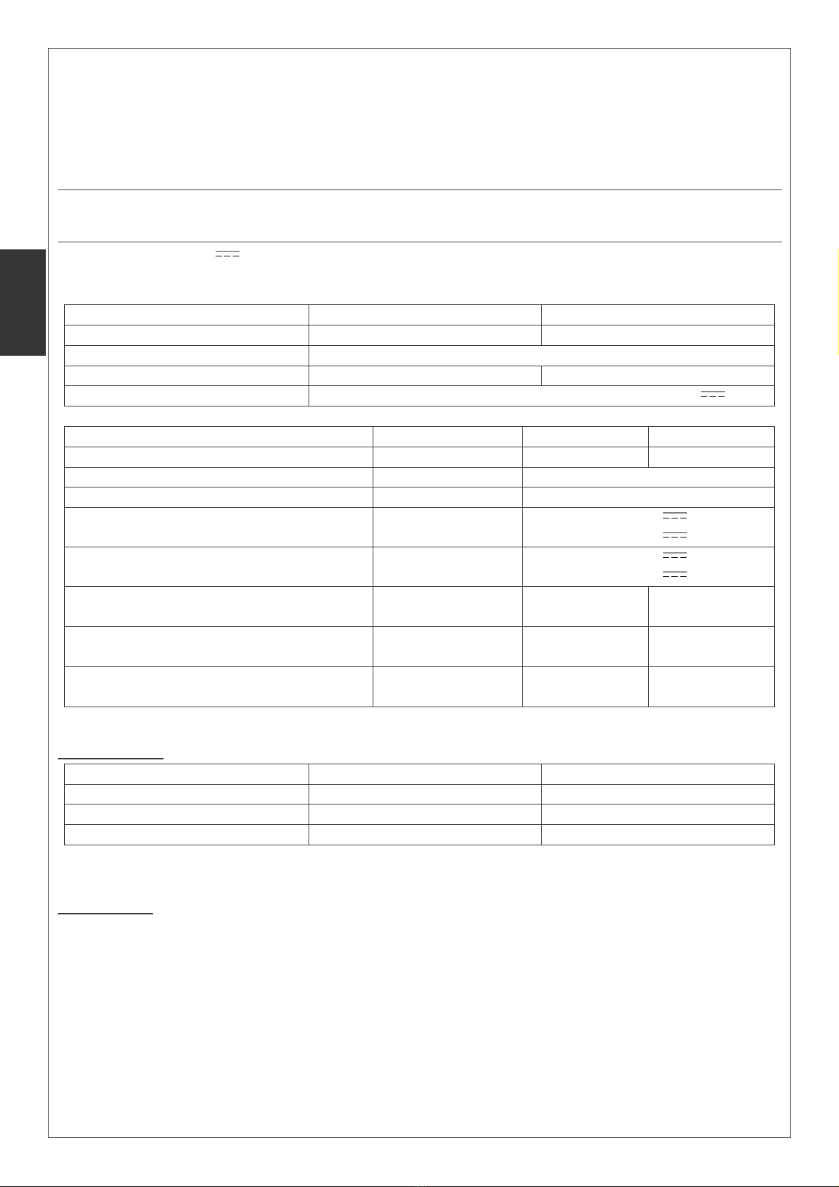
Collegamenti
Inserire un interruttore di rete onnipolare nell’installazione elettrica dell’edificio.
L’uscita per l’alimentazione 230V~, deve essere collegata con cavi a doppio
isolamento.
Collegare i conduttori con la sigla 230V~ ai morsetti d’ingresso della tensione di rete e quelli
contrassegnati con 18V~ all’ingresso della scheda della centrale.
Porre un capicorda ad occhiello sul filo di terra e fissarlo alla torretta filettata
contrassegnata col riferimento di terra.
Cap. 3a - Inserimento nel contenitore - POWER 1Q
La scheda del POWER 1Q va messa a terra collegando il morsetto (posizione 6) indicato con
l’apposito simbolo alla torretta contrassegnata col riferimento di terra.
Il trasformatore toroidale va collegato nel seguente modo:
(1) Fase 220V~
(2) Neutro 220V~
(3) 18V~
(4) 18V~
(5) Guaina H03VV 2 x 0.50
(6) Morsetto di terra
(7) Guaina doppio isolamento
(8) Circuito elettronico
(9) Fusibile
Fissaggio del trasformatore toroidale alla centrale
Per il fissaggio utilizzare le strip biadesive in dotazione.
Attaccare le strip biadesive sul fondo del trasformatore ed appoggiare lo stesso alla centrale,
con una leggera pressione, nella posizione evidenziata nella figura a lato.
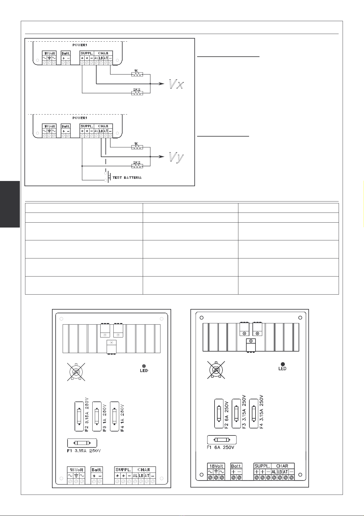
Cap. 3b - Inserimento nel contenitore - POWER 4Q
Cap. 3c - Warning
L'alimentatore deve essere installato all’interno del suo contenitore. Non é ammesso
l'alloggiamento di altre apparecchiature all'interno del gruppo di alimentazione ad eccezione
del trasformatore e la batteria.
L'inversione dei morsetti "230V ~" con quelli "18V ~" comporta la bruciatura del fusibile posto
sul morsetto di ingresso dell'alimentazione di rete.
- 3 -

Cap. 4 - Uscite di controllo analogico
Controllo Alimentazione
Vx = 3.25 V (Mancanza Rete)
Vx = 4.3 V (Rete Ok)
Controllo Batteria
Vy = 4.3 V (Batteria Carica)
Vy = 4.14 V (Batteria Bassa)
Vy = 3.7 V (Batteria Mancante)
Cap. 5 - Fusibili
3.15 A - 250 V rapido1 A - 250 V rapido
F4: Protezione della seconda
uscita positiva (quella di destra)
3.15 A - 250 V rapido1 A - 250 V rapido
F3: Protezione della prima uscita
positiva (quella di sinistra)
6 A - 250 V rapido3.15 A - 250 V rapido
F2: Protezione contro l'inversione
di polarità della batteria interna
6 A - 250 V rapido3.15 A - 250 V rapido
F1: Protezione sull'ingresso
dell'alternata in bassa tensione
1A - 250 V - ritardato250 mA - 250 V - ritardatoFusibile ingresso su 230 V~ POWER 4QPOWER 1QFusibile - Protezione
Scheda POWER 1Q Scheda POWER 4Q
- 4 -

Cap. 6 - Tamper antistrappo
Tutte la antimanomissioni del contenitore del
POWERQ devono essere collegate all'ingresso tamper
della centrale, avendo cura di installare in modo
corretto il kit antistrappo dato in dotazione.
1. Forare la parete in corrispondenza del foro sul
fondo del contenitore destinato all'alloggiamento
dell'antistrappo.
2. Inserire il tassello nel foro sulla parete ed avvitare
il distanziatore.
3. Inserire dall'esterno l'antistrappo sull'apposito foro
sul fondo del contenitore.
4. Fissare saldamente il contenitore alla parete,
controllando che il distanziatore avvitato sul
tassello vada a premere sulla molla del pulsante
dell'antistrappo.
Cap. 7 - Collegamento con SAT03
E’ una scheda satellite di espansione delle funzioni della centrale a 8 ingressi espandibili a 16, a
singolo o doppio bilanciamento.
- 5 -

- 6 -
L’ AVS ELECTRONICS S.p.A. si riserva il diritto di apportare modifiche in qualsiasi momento e senza preavviso.
Via Valsugana, 63
Curtarolo (Padova) ITALY
Tel. 049 96 98 411 / Fax. 049 96 98 407
www.avselectronics.com
Assistenza Tecnica: 049 96 98 444
support@avselectronics.com

Curtarolo (Padova) Italy
www.avselectronics.com
- 7 -
IST0155V2.0
CERTIFIED
QUALITY SYSTEM
ISO9001

Chapter 1 - Description
Additional power supply unit.
Chapter 2 - Technical Features
Stabilized at 13,8 V and limited in current. The use current depends on battery used,
according to specs here below.
nominal stabilized tension of supplying 13,8 VTension
430 mA270 mAMax. consumption
230 V ~ (+/-10%) 50 HzMains
CSv - IMQ U0704IMQ Certificate
POWER 4QPOWER 1QModel
3.42 A
580 mA
920 mA
580 mA
external use
battery recharge
Available current with 15 Ah. back-up
battery
3.55 A
450 mA
1050 mA
450 mA
external use
battery recharge
Available current with 12 Ah. back-up
battery
3.75 A
250 mA
1.250 A
250 mA
external use
battery recharge
Available current with 7 Ah. back-up
battery
13.8 V
13.7 V
empty
max charge
Output tension at 230 V~ +10%
13.8 V
13.4 V
empty
max charge
Output tension at 230 V ~ - 10%
0.4 Vppmax chargeRipple at 230 V~ -10%
from +5 °C at +40°CWorking conditions
4 A1.5 ANominal current
POWER 4QPOWER 1QModel
Size
350 x 450 x 150 mm.355 x 340 x 110 mm.box
75 x 65 x 60 mm.81 x 65 mm.transformer
107 x 160 x 55 mm107 x 160 x 55 mmboard
POWER 4QPOWER 1Q
Protections
protected against battery polarity-inversion.
protected against line short-circuit.
THE RESPECT OF THE NORMS WITH REGARD TO ELECTROMAGNETIC COMPATIBILITY
FOR CE APPROVAL IS ASSURED ONLY IF THE PRODUCT IS PROPERLY INSTALLED IN
ONE OF THE BOXES SUPPLIED BY THE MANUFACTURER.
- 8 -

Chapter 3 - Positioning into the box
Accessories
The supply unit is provided with Faston cable for battery connection.
Connections
Insert a single-pole switch in the electrical installation of the building .
Output for supplying 230 Volt ~ by use of double-isolation cable.
Connect the wires marked by 230 V ~ to the input terminal of mains and those marked by
18V ~ at the input of the supply unit board.
Also connect the earth-wire to all terminals marked by the symbol of the Earth.
Chapter 3a - Positioning into the box - POWER 1Q
The board of POWER 1Q must be connected to earth by connecting the terminal, in position 6,
marked by the proper symbol, to the tower marked by earth reference.
The toroidal transformer must be connected in the follwoing
way:
1) Mains 230 V ~
2) Neutral 230 V ~
3) 18 V ~
4) 18 V ~
5) Shield H03VV 2x0.50
6) Earth terminal
7) Double-isolation shield
8) Electronic circuit
9) Fuse
Fixation of the toroidal transformer to the control panel
For fixation, use the bi-adhesive stripes given within.
Stick the bi-adhesive stripes on the bottom of the transformer and stick it to the control panel
box making a light pression, in the position shown in the drawing
Chapter 3b - Positioning into the box - POWER 4Q
Chapter 3c - Warning
The supply unit POWER Q must be installed in the box. The location of other devices inside
the supplying group is not allowed, with the exception of transformer and battery.
The inversion of the terminals 230 V ~ with those 18V ~ causes the fuse placed on the input
terminal of the mains, to burn.
- 9 -

Chapter 4 - Outputs of analogical control
Supplying control
Vx = 3.25 V (Mains failure)
Vx = 4.3 V (Mains Ok)
Battery control
Vy = 4.3 V ( charged battery)
Vy = 4.14 (low battery)
Vy = 3,7 V (missing battery)
Chapter 5 - Fuses
3.15 A - 250 V quick1 A - 250 V quick
F4: Protection of the second
positive output (on the right))
3.15 A - 250 V quick1 A - 250 V quick
F3: Protection of the first positive
output (on the left)
6 A - 250 V quick3.15 A - 250 V quick
F2: Protection against polarity
inversion of inside battery
6 A - 250 V quick3.15 A - 250 V quick
F1: Protection on the alternate
input in low tension
1A - 250 V - delayed250 mA - 250 V - delayedInput fuse on 230 V ~
POWER 4QPOWER 1QFusibile - Protezione
POWER 1Q Board POWER 4Q Board
- 10 -

Chapter 6 - Anti Tamper
All anti-tamper of POWER Q box must be connected to
the input tamper of the control panel, having care to
install the anti-tamper kit given within, in the correct
way:
1. Drill the wall in correspondance of the hole on
the bottom of the box receiving the anti- tamper
2. Insert the dowell into the hole on the wall and
screw the spacer
3. Insert the anti-tamper from outside in the hole on
the bottom of the box
4. Fix firmly the box to the wall, checking that the
spacer screwed onto the dowell press onto the
anti-tamper push-button spring
Chapter 7 - Connection to SAT03
SAT03 is an extension board of the functions of the control panel, it has 8 inputs which can be
extended to 16, at single our double balancing.
- 11 -

- 12 -
Via Valsugana, 63
Curtarolo (Padova) ITALY
Tel. 049 96 98 411 / Fax. 049 96 98 407
www.avselectronics.com
Assistenza Tecnica: 049 96 98 444
support@avselectronics.com
AVS ELECTRONICS S.p.A. reserves the right to modify the technical and esthetical characteristic of the products at any time.
This manual suits for next models
1
Table of contents
Languages: