AVS TITAN HD-SDI8 User manual

0
TITAN HD-SDI8 / TITAN HD-SDI16 / TITIAN HD-SDI16X
User's Manual
Full HD Digital Video Recorder
HD-CCTV DVR
1
HD-CCTV DVR
Install & User Guide
HD-CCTV DVR Manual.
Thank you for purchasing a AVS Digital Video Recorder.
Before installation or operation please become familiar with the user manual and other referenced manuals
mentioned in the booklet.
User manual, software and hardware described here are protected by copyright by law. With the exception
of copying for general use within fair use, copying and reprinting of the user manual, either partially or in
entirety, or translating it into any another language without the consent of our Corporate office is strictly
prohibited.
Product Warranty and Limited Responsibility
The manufacturer does not assume any responsibility concerning the sale of this product and does not
delegate any right to any third party to take any responsibility on its behalf. The product warranty does not
cover cases of accidents, negligence, alteration, misuse or abuse. No warranty is offered for any attachments
or parts not supplied by the manufacturer.
The manufacturer does not assume any responsibility for followings
Malfunctions due to negligence by user
Deliberate disassembly and replacement by user
Connection of power source other than a properly rated power source
Malfunctions caused by natural disasters (fire, flood, tidal wave, etc)
The warranty period for HDD is one year
Any data damage due to HDD damage
The product is not for exclusive use of crime prevention but for assistance in cases as fire or theft. We
take no responsibility for damage from any incident.
This equipment has been tested and found to comply with the limits for a Class A digital device, pursuant to part 15 of the FCC Rules.
These limits are designed to provide reasonable protection against harmful interference when the equipment is operated in a
commercial environment.
This equipment generates, uses, and can radiate radio frequency energy and, if not installed and used in accordance with the
instruction manual, may cause harmful interference to radio communications. Operation of this equipment in a residential area is likely
to cause
harmful interference in which case the user will be required to correct the interference at his own expense.
Correct Disposal of This Product (Waste Electrical & Electronic Equipment)
(Applicable in the European Union and other European countries with separate collection systems)
This marking on the product, accessories or literature indicates that the product and its electronic accessories (e.g. charger, headset,
USB
cable) should not be disposed of with other household waste at the end of their working life. To prevent possible harm to the
environment or human health from uncontrolled waste disposal, please separate these items from other types of waste and recycle
them responsibly to promote the sustainable reuse of material resources.
Household users should contact either the retailer where they purchased this product or their local government office, for details of
where and how they can take these items for environmentally safe recycling.
Business users should contact their supplier and check the terms and conditions of the purchase contract. This product and its
electronic accessories should not be mixed with other commercial wastes for disposal.
Correct disposal of batteries in this product
(Applicable in the European Union and other European countries with separate battery return systems.)
This marking on the battery, manual or packaging indicates that the batteries in this product should not be disposed of with other
household waste at the end of their working life. Where marked, the chemical symbols Hg, Cd or Pb indicate that the battery contains
mercury, cadmium or lead above the reference levels in EC Directive 2006/66. If batteries are not properly disposed of, these
substances can cause harm to human health or the environment.
To protect natural resources and to promote material reuse, please separate batteries from other types of waste and recycle them
through your local, free battery return system.
Copyright ©2014 AVS Uriel Systems, Inc. All rights reserved.

2
Introduction
Warning
Warning
Please do not bend or press power cord by force which could lead to fire.
Be careful not to pull or plug with wet hands to avoid fire or electric shock.
In case of changing built-in lithium battery, it should be replaced with same brand or similar one to prevent
a danger of explosion. Since old batteries could be a factor of environment contamination, please disposed
of them properly.
Do not throw the batteries in fire or heating units. Neither short circuit nor disassembly is prohibited.
Do not recharge battery used for remote controller.
Do not open the top cover otherwise it could lead to electric shock and product damage.
The previous recorded data is deleted if record continues when HDD is full so please check disk setup
status.
Manufacturer takes no responsibility for any damaged data due to customer’s carelessness or negligence.
A-rated device(Broadcasting Communication Equipment for business use only)
Users/Sellers should under this is A-rated device for business use only and it must not be used outside of
family.
Caution
Do not place heavy objects on top of the product.
Product is for indoor use only and it is not water or damp proof. Use product to its environmental
specifications (Temperature & Humidity). To clean the product, gently wipe the outside with a clean dry
cloth.
Product uses AC power of 110V ~ 240V. Be cautious not to cause electric damages to the product.
Be careful not to drop the product. Physical shocks may harm the product including internal HDD. In
addition, please do not throw or drop it.
Product is made of metal you can hurt another human if you throw or used as a weapon. Keep away from
the reach of children and install in a safe place.
If Product does not operate properly, please contact the closest AVS distributor for service. Tampering or
disassembling the product will void the warranty.
The product can transmit real time video over network or internet and can be used for monitoring purpose
depending on installation sites. So please check and review related regulations before installation.
Experience and technical skills are needed for the installation of this product. Improper installation may cause
fire, electric shocks, or defects. Contact the nearest AVS dealer for installations.
Contents of the manual can differ according to firmware or Software upgrade, and the appearance of products
may be changed for the improvement of quality without an advance notice
◈System power off
In case user turn off device by force while device is working, it could give damage on HDD and device so
please turn off device safely using power button located in the front panel. You should install a UPS system for
safe operation in order to prevent damage caused by an unexpected power failure.
◈Working Temperature
The working temperature of the product is 5°C~45°C or 41°F~113°F. DVR may not work properly if left in low
temperature for a long period of time. If such is the case, then store at room temperature for some time
before using it again.

3
Contents
Introduction 2
Warning 2
Key Features 5
Specification by Models 6
Components 7
Product Description 8
Installation 13
Connecting other devices 16
Usage 23
Default setting 24
Menu usage 29
Menu structure 29
FUNC menu 29
Monitoring 29
Search and playback 34
Playback 34
Screen composition/names of the functions 35
Copy 36
Configuration 38
System configuration 38
Disk 39
Network 45
Device settings 49
Event Configuration 54
Recording set up 58
Web Viewer 61
System requirement 61
Installation 61
login 61
User set up 61
Monitor 62
Playback 65
JAVA Viewer 68
4
System requirement 68
Installation 68
Login 68
Monitor 69
Playback 70
Webeye 71
Mobileviewer 71
Appendix 72
Problem solving [FAQ] 72
Compatible HDD 74
Factory default set-up values * 74
Product specification 78
Product Dimension 81
5
Key Features
Penta-Brid *
Various video format from 1080P, 720P, 960H, NTSC/PAL up to
DoubleReachTM can be displayed simultaneously.
It supports real-time live monitoring and record/playback on
various format and it records from 5 seconds before event and
record up to 30fps per channel.
Various video record
- HD 1080p
- HD 720P
- SD 960H
- SD (NTSC/PAL)
- DoubleReachTM
Supports manual & schedule recording at all times.
Supports archiving event list(sensor, video loss, motion detection, Text)
Max 5 seconds pre-alarm recording per each channel
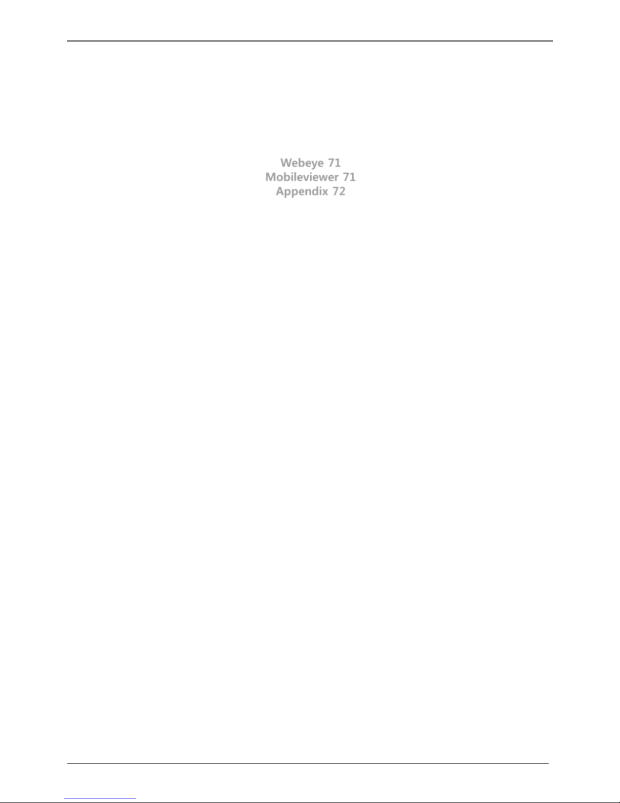
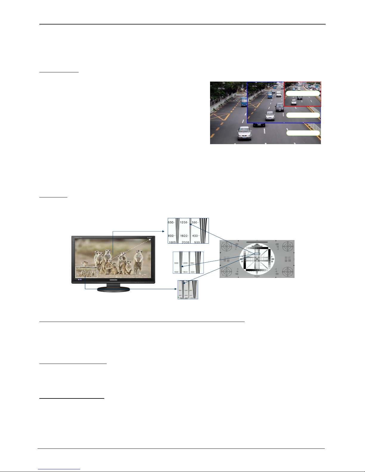
FULL HD
FULL HD high quality video shows far superior resolution than SD video product. Over 1200 TV lines at 1080p
resolution can be visible.
SD
Full HD
D1 Resolution
1080P Resolution
720P Resolution
DoubleReach™(Enhances transmission distance by Max. 400m)
It is a technology that increases transmission distance by 400m for HD-SDI cameras.
HD-SDI transmission distance can be reached up to 400m if DR101P-TX , which is DoubleReach transmitter,
is connected with HD-SDI camera or if D1080 series camera is connected directly to Penta-Brid DVR.
RAID 1/5/10 Levels *
Supports RAID.
Via RAID MANAGER, various RAID Levels can be configured without additional RAID devices.(RAID 1/5/10)
Surveillance Screens
Every channel will display HD streams without interruptions and will offer many different types of screens.
Various Surveillance Screen Mode - Single, Multi Screens (1,4,9,10,13,16,CustomA,B,C) *
Auto Screen Sequence, Event Pop-up
SPOT –Single, Multi screen division(1,4,9,16), Auto screen sequence
* Varies between different models
Full HD : 1080p
HD : 720p
SD : D1

6
Voice Recording
Supports real time voice input and recording function.
Real time 4ch voice input and recording function
Input : 4ch RCA, Output : 1ch RCAI(Rear), 1ch HDMI(Rear)
Audio recording and playback can be played Simultaneously
Search and Playback
Various useful functions for search & playback
Simultaneous playback for every channel
Playback by time, date, channel
Time/ Calendar/Event/Thumbnail/Bookmark search
Forward/backward search function of a freeze frame
Save and Backup
You can record video data into the internal HDD, and image can be copied to a USB memory.
Backup device : USB stick
External storage device : e-SATA HDD or NS04R(exclusive storage device) *
Network
Supports LAN, xDSL, and etc., and key functions can easily be controlled by web browser or customized CMS
program.
HD Live monitoring/playback/backup from the remote site
Multi-streaming feature for slow network environment (supports nHD monitoring)
Sending event info(image) using E-Mail/ FTP
Recorded video playback, save, search function, and DVR control function on PC via CMS
Supports 10/100/1000 Mbps Ethernet/xDSL
Managing up to 1024 DVRs with CMS
Others
User friendly GUI and mouse
Easy and simple firmware upgrade, and recorded video back up function using USB stick
Using Ac the PC Playback function, replay the DVR’s HDD on a PC
Supports PTZ control and PRESET function
Easy control of up to 255 DVR with a single remote control
Specification by Models
Model
CASE
HDD
DoubleReach
NS04R
RAID
TITAN HD-SDI16X
Full
SATA*5 + eSATA
O
O
O
TITAN HD-SDI16
Middle
SATA*2 + eSATA
O
X
X
TITAN HD-SDI8
Middle
SATA*2 + eSATA
O
X
X
(O : Supported / X : not-Supported)
* Varies between different models
7
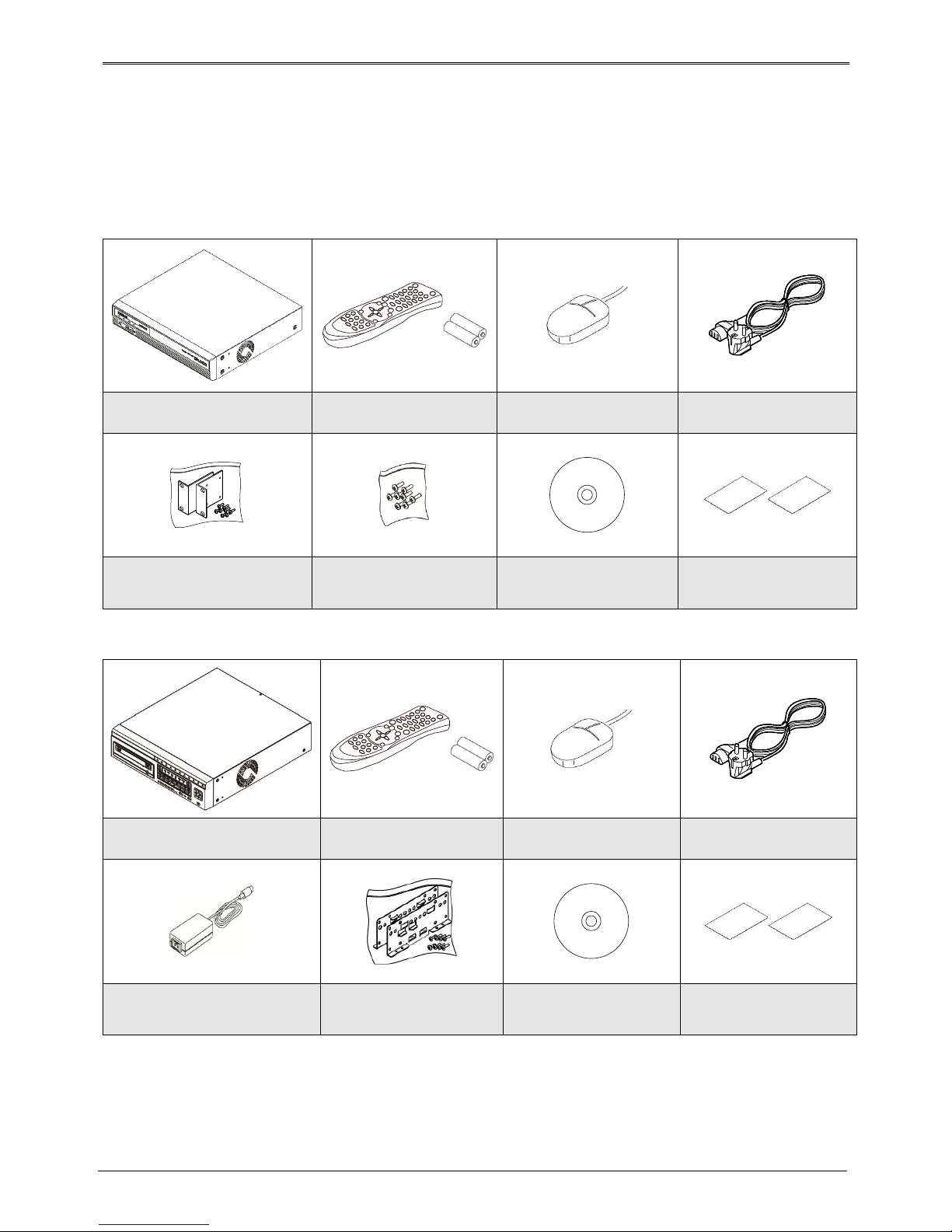
Components
Please check the below to make sure you have every part.
TITAN HD-SDI16X
DVR
Remote Control & Batteries
Mouse
power cord
Rack Bracket
Screws
SW & user guide CD
Installation and user guide
Quick installation guide
TITAN HD-SDI8 /TITAN HD-SDI16
DVR
Remote Control & Batteries
Mouse
power cord
adaptor
Rack Bracket & Screws
SW & user guide CD
Installation and user guide
Quick installation guide
8
Product Description
TITIAN HD-SDI16X
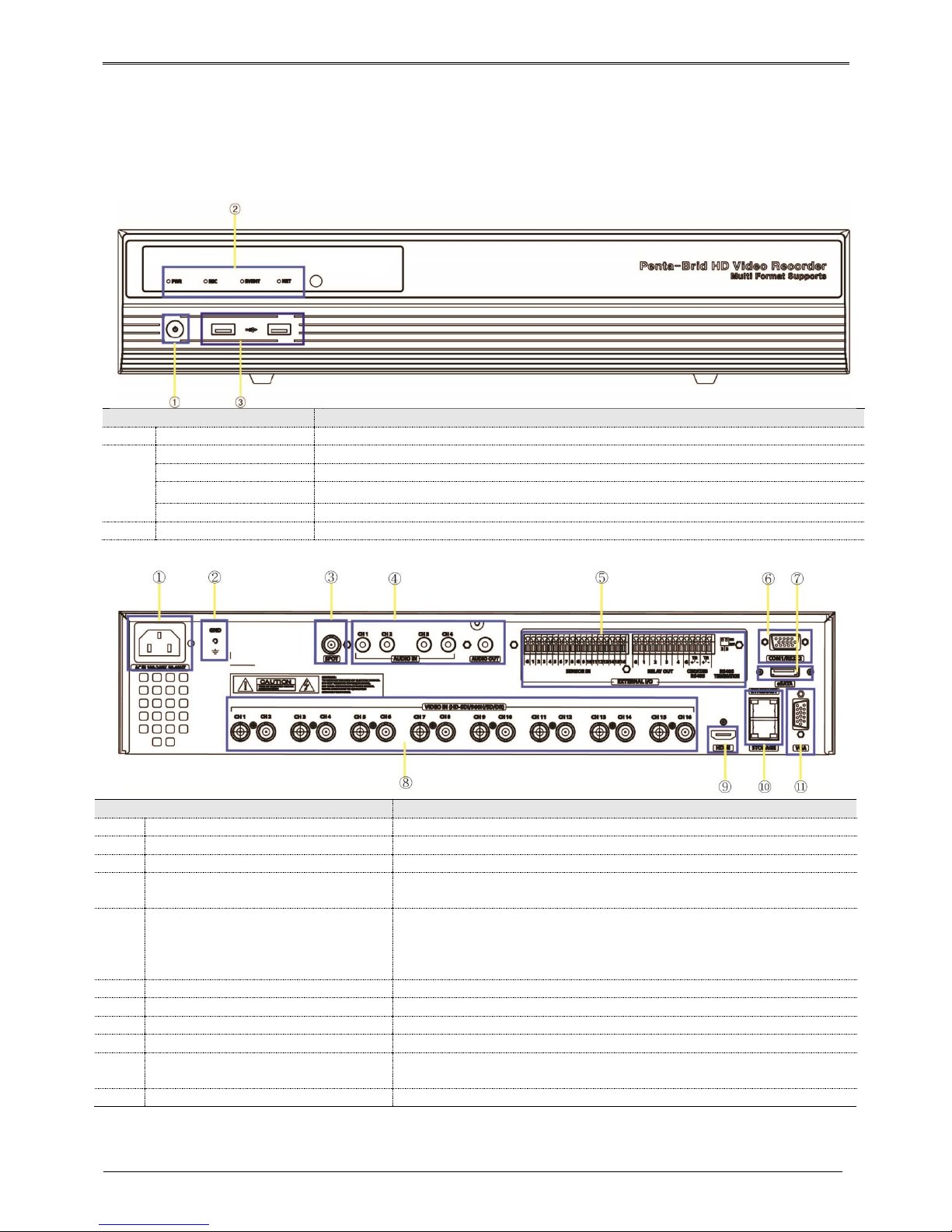
Front view
part name
function description
1
Power
turns ON/OFF the power
2
PWR
It turns on when power is ON
REC
Shows record status while recording
EVENT
Turns on if event is triggered
NET
Shows network connection status and it flickers if network is connected
3
USB port
USB port for flash memory or mouse.
Rear view
part name
function description
1
Power Input
AC100V~AC240V power cord socket
2
Ground Connection
Connection terminals that connects DVR to an outside device
3
SPOT
Connection port for SPOT monitor
4
Audio Input/Output
Audio Input : Audio input connection terminal
Audio Output : Speaker output terminal
5
Sensor, Relay, Com2/3, RS-485 terminating
resisters
Sensor : External sensor input terminal..
Relay : Relay connect terminal.
Com2/3 : For connection with RS-485 device.
Set terminating resisters when using RS-485 method.
6
COM1
RS-232C D-SUB
7
eSATA port
For connection with external eSATA HDD.
8
Channel Input
Camera input BNC port for 1080P, 720P, 960H, NTSC/PAL, DR cameras
9
HDMI Output
HDMI monitor connection output port
10
Ethernet, Storage
Ethernet : network connecting terminal (RJ-45)
Storage : Exclusive network storage device(NS04R) is connected and used.
11
VGA Output
VGA monitor connection output port.

9
TITAN HD-SDI16 / TITAN HD-SDI8
Front view
part name
function description
1
Power
turns ON/OFF the power
2
PWR
It turns on when power is ON
REC
Shows record status while recording.
EVENT
Turns on if event is triggered
NET
Shows network connection status and it flickers if network is connected
3
USB port
USB port for flash memory or mouse.
TITAN HD-SDI16
Rear view
part name
function description
1
Power Input
Connection socket for DC 12V power code
2
Ground Connection
Connection terminals that connects DVR to an outside device
3
SPOT
Connection port for SPOT monitor
4
Audio Input/Output
Audio Input : Audio input connection terminal
Audio Output : Speaker output terminal
5
Sensor, Relay, Com2/3, RS-485
terminating resisters
Sensor : External sensor input terminal..
Relay : Relay connect terminal.
Com2/3 : For connection with RS-485 device.
Set terminating resisters when using RS-485 method.
6
COM1
RS-232C D-SUB
7
eSATA port
For connection with external eSATA HDD.

10
part name
function description
8
Channel Input
Camera input BNC port for 1080P, 720P, 960H, NTSC/PAL, DR cameras
9
HDMI Output
HDMI monitor connection output port
10
Ethernet
Ethernet : network connecting terminal (RJ-45)
11
VGA Output
VGA monitor connection output port.
TITAN HD-SDI8
Rear view
part name
function description
1
Power Input
Connection socket for DC 12V power code
2
Ground Connection
Connection terminals that connects DVR to an outside device
3
SPOT
Connection port for SPOT monitor
4
Audio Input/Output
Audio Input : Audio input connection terminal
Audio Output : Speaker output terminal
5
Sensor, Relay, Com2/3, RS-485
terminating resisters
Sensor : External sensor input terminal..
Relay : Relay connect terminal.
Com2/3 : For connection with RS-485 device.
Set terminating resisters when using RS-485 method.
6
COM1
RS-232C D-SUB
7
eSATA port
For connection with external eSATA HDD.
8
Channel Input
Camera input BNC port for 1080P, 720P, 960H, NTSC/PAL, DR cameras
9
HDMI Output
HDMI monitor connection output port
10
Ethernet
Ethernet : network connecting terminal (RJ-45)
11
VGA Output
VGA monitor connection output port.

11
Remote control
Can use every function of the DVR and control
several DVRs with only one remote control.
To be able to use the remote control, please
create a user ID on the remote control ID
section of system settings. (See the right
picture for working angle of a remote control)
MON REC
ID
Select Remote ID
COPY
Save record data into USB or CD/DVD
SEQ
Auto screen switch
MULTI
Screen division change
SELECT
No use
BACKUP
No use
MON
Change monitor
MENU
Change menu screen
ENTER
Select menu
Stop, Slow backward, Slow
forward, Pause
PTZ
Control PAN/TILT
LOAD PRESET
Lead PRESET
SAVE PRESET
Save PRESET
Search speed down, Reverse
playback, Forward playback,
Search speed up
EXIT
Cancel setup, get out of menu
Playback speed down,
stop, playback/pause,
playback speed up
HELP
Execute FUNC menu
RECORD
User record start or stop
+10
Select number over 10(+10 +1)
CHANNEL BUTTON
Select channel
ZOOM
Execute digital zoom
SEARCH
Display search menu
RELAY OFF
Alarm OFF manually
LOCK
Lock monitor screen
RELAY ON
Alarm ON manually
Remote control A

12
Remote control B

13
Installation
Check settings
This DVR is high quality security device with a high capacity built-in HDD and important curcuits. Before
installation, please read carefully below recommendations as high internal temperature of the product can lead
to damages and shorten product life cycle.
Recommendations on installing a DVR in a rack.
1. Don’t seal the inside of rack where DVR is installed.
2. Keep airflow through inlet and outlet.
3. If there is another device installed in the rack, secure additional space or install air ventilation.
4. Installation of an air circulation fan around each inlet and outlet is strongly recommended.
(Install filter around inlet or outlet for harmful substances)
5. Keep ambient temperature between 5°C~45°C around DVR.
Warnings if HDD is installed
1. Please be extra careful not to damage HDD as it easily breaks.
2. During installation, make sure insulated coat doesn’t come off or isn’t placed in the worng place.
3. Don’t lose screws and parts.
(If screws an parts are not screwed or assembled correctly, product may not operate)
4. Check HDD compatibility list HDD
(Please check with CS team)
5. Partition table must be removed for HDDs used in PC or other DVR models before installation.
HDD installation
TITAN HD-SDI16X
1. Unscrew bracket screws that are fixing it to a DVR..
2. Push HDD bracket to a direction shown in the right picture and
separate from fixtures.
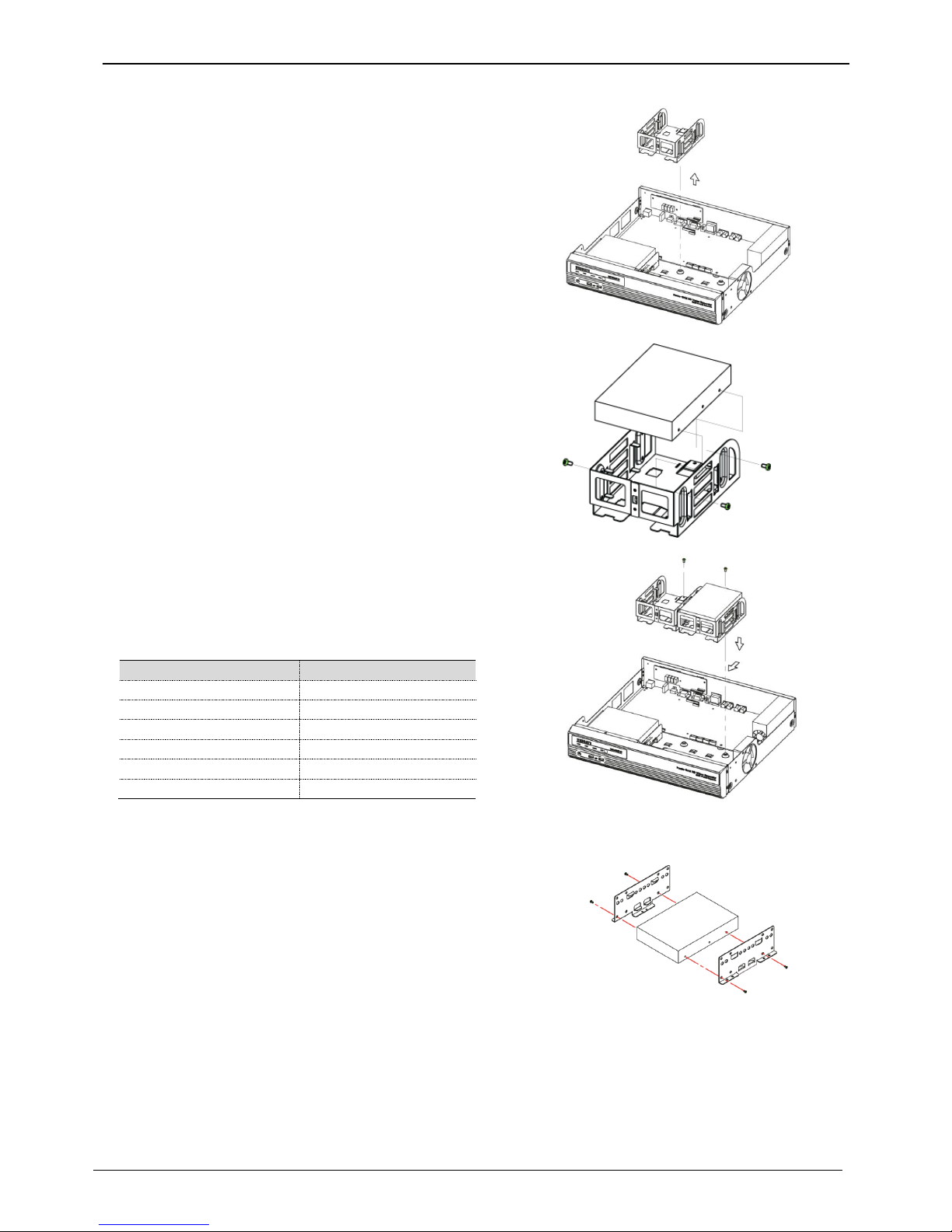
14
1. Lift HDD bracket to a direction shown in the right picture and
separate from the bottom.
2.Place HDD in a HDD bracket and fasten 4 screws on each side.
3. Place HDD bracket fastened with screws in DVR and fasten it on
the bottom with screws.
<Note>
Below is SATA cable socket sequence of a mainbaord.
Up to 5 HDDs can be installed inside DVR.
Main Board
Disk Manager
INT A
INT A
INT B
INT B
INT C
INT C
INT D
INT D
INT E
INT E
eSATA
eSATA
TITAN HD-SDI8 / TITAN HD-SDI16
1. Tighten the both side of HDD bracket using screws.

15
2. Install HDD bracket with HDD into DVR then hold it with screw to
fix it to the bottom part of DVR.
<Note>
Socket arrangement of SATA cable in main b’d is as follows.
Two HDDs can be installed in DVR.
Main b’d socket
Disk manager
INT A
INT A
INT B
INT B
eSATA
eSATA
Adding HDD
Remove the power cord before installation to protect DVR against possible damage and an electric shock
Please call the store you purchased the product from if it isn’t operating correctly due to installation or
configuration mistakes.
Warnings regarding Data loss
Please handle with care so HDD data isn’t damaged.
Check HDD compatibility before installing additional HDD.
Be careful not to give any shock on HDD during operation which could lead to possible damage or malfunction
.
Cases when HDD and its data can be damaged.
To minimize the data loss, please copy data as often as you can.
Physical shock during disassembly or installation may lead to Data damage.
Sudden power outage or turn off of DVR can damage HDD.
Please don’t try to move or shock DVR while HDD is working.
16
Connecting other devices
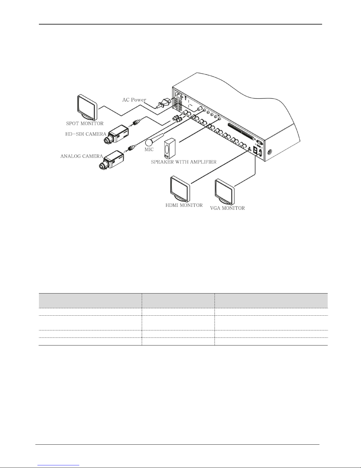
Basic connections
Connecting a monitor
Check monitor resolution and connect to DVR.
HDMI Port : 1920 x 1080p
<Note>
We strongly recommend using HDMI certified cable when connecting to DVR.
Connecting a Camera
Connect 1080P, 720P, 960H, NTSC/PAL camera using recommended cable.
Recommended cable *
*Depends on manufacturer and models.
<warnings>
Transmission distance will be affected by cable types and installation site environment
Transmission distance of the chosen cable will be various based on reduction rate of 750MHz
(reduction rate of dB/100m < 25dB is recommended)
Foamed or high-foamed trishield cable is recommended.
Impedance 75Ω must be used for coax cable connection and connector work.
Beware of deformation of cable due to high pressure over the cable.
Don’t pull the cable with too much force.
For DVR input/output, cables will be tied at the rear of the rack. If tied too tightly, inside/outside insulator can be
deformed so tie it loosely within cable’s curvature range.
Cable Type
HD-SDI transmission
distance *
Use
5C2V
about 90M
Analog signal
4C-FB(T), 4C-HFB(T), RG59
about 140M
High-foamed cable, double or triple
shielded cables are recommended
5C-FB(T), 5C-HFB, L-6CHD, RG6
about 180M
HD-SDI cable
5C-HFBT
about 200M
HD-SDI cable

17
Connecting a power cord
When power cord is connected, DVR starts booting automatically.
How to turn off DVR while it is operating : press power switch for 5 seconds, and a pop-up window will appear,
then select “YES” to turn off the power. For turn back on the power again, push the Power button.
Connecting an audio
RCA cable to connect audio input/output devices to DVR
Connecting external device
Connecting USB Device
USB port can be used for copy of recorded data and for mouse.
See below table for USB Device specifications.
<Note>
USB stick needs to be FAT32 formatted.
DVR may not recognize USB Flash memories that require additional program on MS Windows.
Connecting eSATA Device
If external eSATA storage is used, it can be connected to a rear eSATA port. Additional power for eSATA device
will be required as DVR doesn’t supply power.
.
<Note>
1. Check compatibility of eSATA with DVR as not all eSATA are compatible with DVR.
2. If eSATA is connected to DVR when it is on, it may not be recognized depending on external devices. So
we recommend following the below steps.
1) Turn off DVR.
2) Turn off eSATA then connect it to DVR.
3) Turn on eSATA.
4) Turn on DVR.
Connecting NS04R
Connecting to DVR
(1) Connect NS04R to DVR using Gigabit Ethernet cable.
(2) NS04R’s DVR Port and DVR’s Storage Port must be connected directly.
<Note>
1)
Use Gigabit Ethernet Cable(Category-6) for Network cables to connect to DVR. Other cables are not
compatible with AVS DVR.
2) NS04R and DVR must be connected by cables and normal operation isn’t guaranteed if Hub is used.
*
USB specifications
Ver 2.0 or later
Usable device
USB Stick
Voltage specifications
DC 5V / Max. 200mA

18
Set ID configuration
Set ID using Rotary switch located at rear panel.
Set each different ID in case of over 2 NS04Rs are
connected.
Using tool such as Driver to set ID. For Group ID swich, it is
set as ID in a unit of 10 when ID switch of NS04R is in a
unit of 1.
ID setup value must be within 0~99.
EX) ID will be 23 when switch is set as Group ID=2,
NS04R ID=3
<Note>
1) It approximately takes a minute to turn on the power and to connect NS04R to DVR.
While it is connecting, 4 LEDs on the front will be turned on in order and all 4 LEDs may be turned on or
off when it is connected to DVR. HDD list can be checked on the disk manager.
Connecting input/out terminals
Wire end handling
See below for wire end handling used in terminal block. Please work on single line and multiple line as they
have different thicknesses.
Wire insertion/removal
As shown in the picture, push the lever to insert or remove a
wire.
Connecting the sensor
specification
below requirements need to be met in order to connect the sensor
Specifications
Input Channel #
16EA Transistor input
Input Type
N.C, N.O support
Supported sensor
Dry contact sensor
Connection method
Connect the trimmed wire to terminal block
Performance
Available input
pulse range
Minimum 500ms
Output current
Standard DC 12mA
- Multiple lines : Peel off the recommended length(8~10mm) and lead-coat it. Use AWG 22 ~ 26.
- Single line : Peel off the recommended length(8~10mm) and use AWG 20 ~ 26.
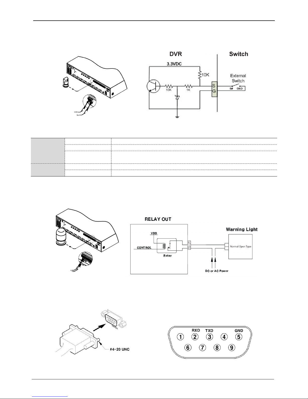
19
Connecting sensor input terminal
Please see the picture for sensor input. The below picture is an example of connecting Dry Contact sensor type.
Please refer to “Wire Handling” for more information.
Connecting relay
specifications
Please see the below table for alarm output requirements.
Specifications
Output Ch. *
4ch relay output
Output type
Dry Contact
Connection
method
Connect the trimmed wire to terminal block
Performance
DC
30V / 1A
AC
125V / 0.5A
* Varies between different models
Connecting relay
Please refer to the below picture in regards to connecting R1~R4 output. Below picture is an example of
connecting a light bar. Please see “wire end handling” in regards to connecting/removing wires.
Connecting COM1 serial port with external devices
Connecting Text input device (ATM / POS / Access Control)
Using COM1/RS232, TEXT DATA can be recorded with synchronizing POS/ATM.
As shown in the picture, for a set up to connect COM1/RS232 (D-Sub 9pin), set up serial & text info under
“device” menu.
This manual suits for next models
2
Table of contents
Other AVS DVR manuals


Popular DVR manuals by other brands

Wow
Wow Digital Video Recorder Quick reference guide

ATV Falcon
ATV Falcon FA-HDX16-2TB user manual

LAFI-SA
LAFI-SA IVE-1004D-1008C-1016C user manual

Avermedia
Avermedia AverDigi MXR6004 mini user manual

EverFocus
EverFocus PARAGON264x4--32CH Series instruction manual

Crest Electronics
Crest Electronics CDR-1104 user guide


