TECNOLOGIA DI TAGLIO AL PLASMA AD ARIA
Le lame da taglio al plasma funzionano facendo passare un arco elettrico attraverso un gas che passa attraverso un'apertura
ristretta. Il gas può essere aria, ni-trogen, argon, ossigeno. ecc. L'arco elettrico eleva la temperatura del gas al punto che entra in un
quarto stato della materia. Tutti noi abbiamo familiarità con i primi tre: vale a dire, solido, liquido e gas. Gli scienziati chiamano
questo plasma di stato aggiuntivo. Poiché il metallo tagliato è parte del circuito, la conduttività elettrica del plasma fa sì che l'arco si
trasferisca al lavoro. L'apertura ristretta (ugello) che il gas attraversa fa sì che schiaccia ad alta velocità, come l'aria che passa
attraverso un venturi in un carburatore. Questo gas ad alta velocità taglia il metallo fuso.
Il taglio al plasma è stato inventato come risultato del tentativo di sviluppare un processo di saldatura migliore. Molti miglioramenti
hanno poi portato a rendere questa tecnologia ciò che è oggi. Le taglierine al plasma offrono la migliore combinazione di precisione,
velocità e capacità di produrre una varietà di forme metalliche piatte. Possono tagliare molto più fine e più velocemente delle torce
ossiacetileniche.
Come funziona una taglierina al plasma:
I plotter da taglio di base utilizzano l'elettricità per surriscaldare l'aria nel plasma (il 4 ° stato della materia), che viene quindi
soffiata attraverso il metallo da tagliare. I plotter da taglio al plasma richiedono un'alimentazione di aria compressa e
alimentazione CA per funzionare.
Funzionamento:
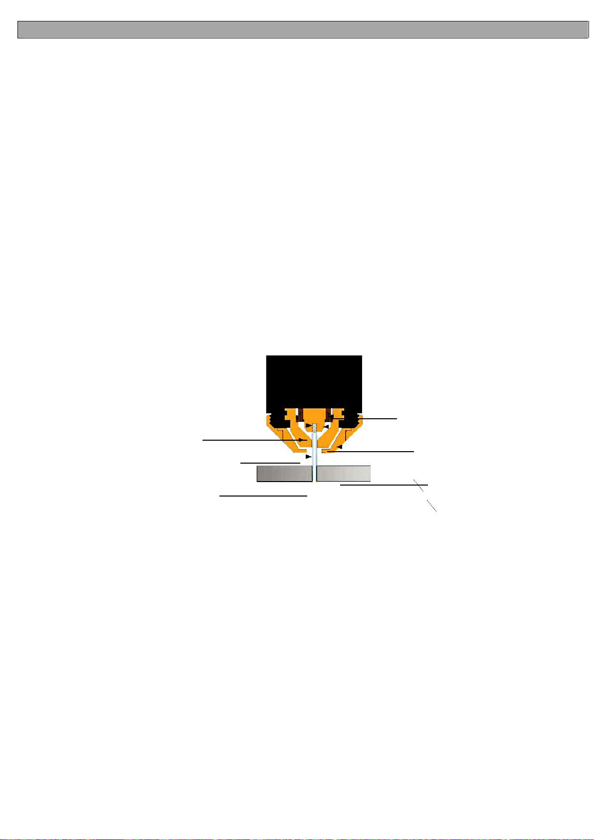
1.
Quando il grilletto è schiacciato, la corrente continua scorre attraverso il filo della torcia nell'ugello.
2. Successivamente, l'aria compressa scorre attraverso la testa della torcia, attraversando il diffusore d'aria che fa fluire l'aria
attorno all'elettrodo e attraverso il foro dell'ugello di taglio.
3. Tra l'elettrodo e l'ugello si stabilisce uno spazio fisso. (L'alimentatore aumenta la tensione al fine di mantenere una corrente
costante attraverso l'articolazione.) Gli elettroni si sviluppano attraverso lo spazio, ionizzando e surriscaldando l'aria creando un
flusso di plasma.
4. Infine, la corrente continua regolata viene commutata in modo tale che non fluisce più verso l'ugello, ma fluisce invece dall'elettrodo
al pezzo da lavorare. Corrente e flusso d'aria continueranno fino a quando il taglio non viene interrotto.
Inserto per elettrodo
Diffusore di aria
ElettrodoUgello
Flusso del plasma
Coppa scudo
Appunti:
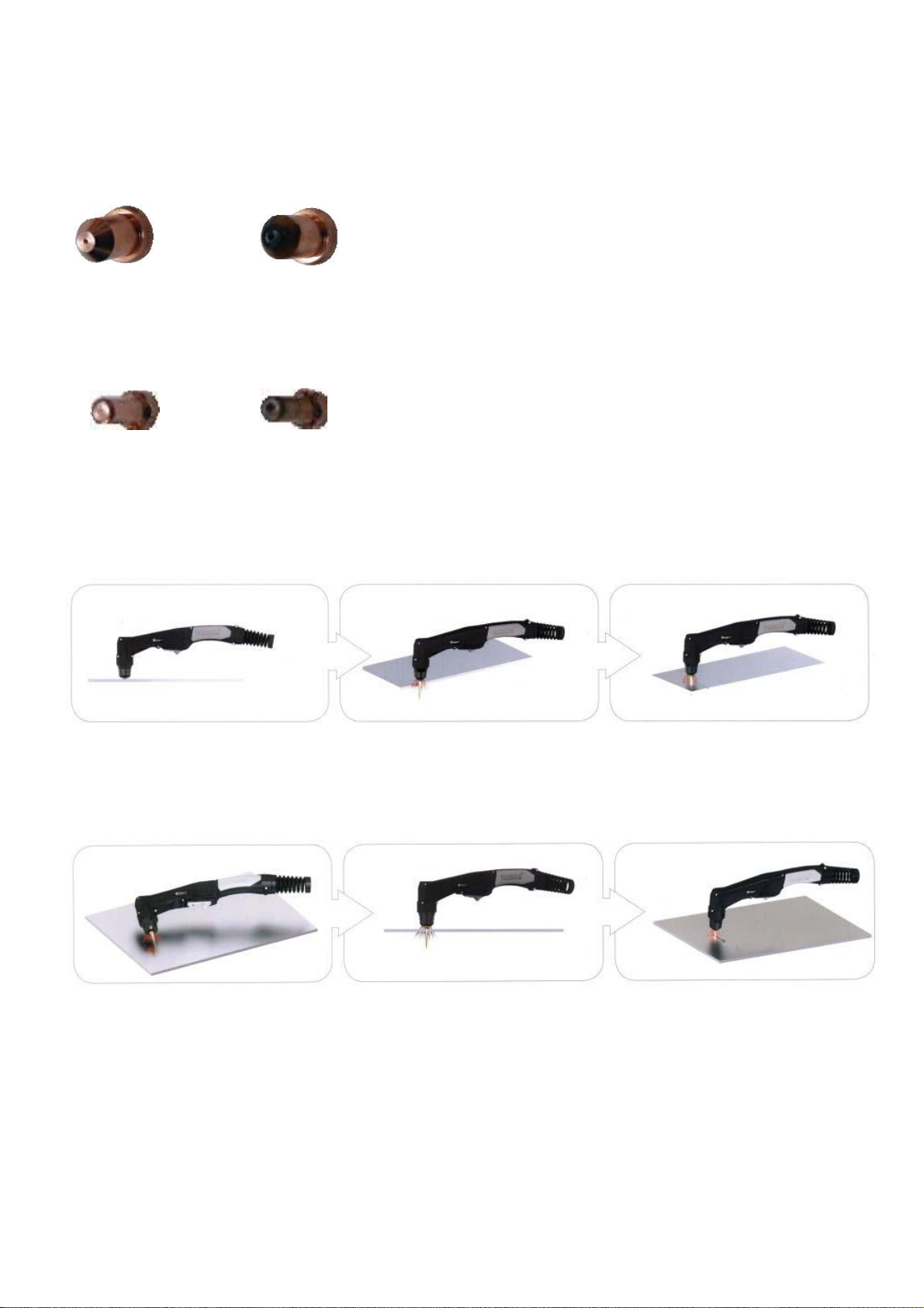
L'ugello e l'elettrodo richiedono una sostituzione periodica. L'elettrodo ha un inserto di materiale altamente conduttivo come l'afnio
e il cerio. Questo inserto si corrode con l'uso, anche l'orifizio dell'ugello si corroderà con l'uso. La qualità dell'aria utilizzata è
fondamentale per una maggiore durata degli elettrodi e degli ugelli, in breve l'aria secca e pulita garantisce una maggiore durata
delle parti, inoltre più pulita e asciutta risulta e meglio sarà. Raccomandiamo l'uso di un filtro dell'aria al plasma.
Quali tipi di materiali può tagliare il plasma?
Praticamente qualsiasi metallo può essere tagliato al plasma incluso acciaio, acciaio inossidabile, alluminio, ottone, rame, ecc.
Qualsiasi spessore da 0,2 mm a 10 mm può essere tagliato, a seconda della potenza del plotter da taglio utilizzato.
Come funziona il taglio al plasma rispetto al taglio con ossitaglio (gas)?
Il taglio al plasma può essere eseguito su qualsiasi tipo di metallo conduttivo: acciaio dolce, alluminio e acciaio inossidabile.
Ad esempio, con l'acciaio dolce, gli operatori sperimenteranno tagli più rapidi e spessi rispetto alle leghe. Tagli di ossitaglio
mediante combustione, o ossidando il metallo che si sta tagliando, quindi limitato all'acciaio e ad altri metalli ferrosi che supportano
l'ossidazione. Metalli come l'alluminio e l'acciaio inossidabile formano un ossido che inibisce l'ulteriore ossidazione, rendendo
convenzionale tagli ossi-combustibili impossibili. Il taglio al plasma tuttavia non si basa sull'ossidazione per funzionare e quindi può
tagliare alluminio, acciaio inossidabile e qualsiasi altro materiale conduttivo. Mentre diversi gas possono essere utilizzati per il taglio
al plasma, la maggior parte delle persone oggi usano aria compressa per il gas plasma. Nella maggior parte dei negozi, l'aria
compressa è facilmente disponibile, e quindi il plasma non richiede gas combustibile e ossigeno compresso per il funzionamento. Il
taglio al plasma è in genere più facile da padroneggiare per i principianti e, su materiali più sottili, il taglio al plasma è molto più
rapido rispetto al taglio con ossi-combustibile. Tuttavia, per le sezioni di acciaio pesanti (da 1 "e superiori), l'ossi-combustibile è
ancora preferito poiché l'ossi-combustibile è tipicamente più veloce e, per le applicazioni con piastre più pesanti sono richieste
macchine plasma ad alta potenza per le applicazioni di taglio al plasma.
Quali sono i limiti al taglio al plasma? Dove è preferito l'ossitaglio?
Le macchine per il taglio al plasma sono in genere più costose di ossi / acetilene. Inoltre, l'ossi / acetilene non
richiede l'accesso alla corrente elettrica o all'aria compressa che potrebbe renderlo un metodo più conveniente per
alcuni utenti. L'ossitaglio può generalmente tagliare sezioni più spesse (> 25 mm) di acciaio in modo più veloce
rispetto al plasma.
ITALIANO