GEA Bock FK30 User manual

GEA Bock FK30
Assembly instructions
09705-01.2018-Gb
Translation of the original instructions
FK30/235 N FK30/275 N FK30/325 N
FK30/235 K FK30/275 K FK30/325 K
FK30/235 TK FK30/275 TK FK30/325 TK
FKX30/235 N FKX30/275 N FKX30/325 N
FKX30/235 K FKX30/275 K FKX30/325 K
FKX30/235 TK FKX30/275 TK FKX30/325 TK

2
D
GB
F
I
Tr
Ru
09705-01.2018-DGbFITrRu
About these instructions
Read these instructions before assembly and before using the compressor. This will avoid
misunderstandings and prevent damage. Improper assembly and use of the compressor can lead to
serious or fatal injury.
Observe the safety instructions contained in these instructions.
These instructions must be passed onto the end customer along with the unit in which the
compressor is installed.
GEA Bock GmbH
72636 Frickenhausen
Manufacturer
Contact
GEA Bock GmbH
Benzstrasse 7
72636 Frickenhausen
Germany
Phone +49 7022 9454 0
Fax +49 7022 9454 137
www.gea.com

3
D
GB
F
I
Tr
Ru
09705-01.2018-DGbFITrRu
Contents Page
1 Safety 4
1.1 Identication of safety instructions
1.2 Qualications required of personnel
1.3 General safety instructions
1.4 Intended use
2 Product description 6
2.1 Brief description
2.2 Name plate
2.3 Type key
3 Areas of application 8
3.1 Refrigerants
3.2 Oil charge
3.3 Limits of application
3.4 N and K versions
3.4.1 Limits of application R134a
3.4.2 Limits of application R407C
3.5 TK version
3.5.1 Limits of application R404A/R507
3.5.2 Limits of application R22
4Compressor assembly 11
4.1 Setting up
4.2 Maximum permissible inclination
4.3 V-belt drive
4.4 Main bearing load
4.5 Installation of electromagnetic clutch assembly
4.6 Pipe connections
4.7 Pipes
4.8 Operating the shut-off valves
4.9 Operating mode of the lockable service connections
4.10 Suction pipe lter
5 Commissioning 15
5.1 Preparations for start-up
5.2 Pressure strength test
5.3 Leak test
5.4 Evacuation
5.5 Refrigerant charge
5.6 Oil level check
5.7 Shaft seal
5.8 Avoiding liquid shocks
6 Maintenance 18
6.1 Preparation
6.2 Work to be carried out
6.3 Shaft seal, emptying the oil reservoir
6.4 Recommended spare parts
6.5 Integrated decompression valve
6.6 Extract from the lubricants table
6.7 Decommissioning
7 Accessories 20
7.1 Thermal protection thermostat
8 Technical Data 21
9 Dimensions and connections 22
10 Installationcerticate 24
11 Service 25

4
D
GB
F
I
Tr
Ru
09705-01.2018-DGbFITrRu
1|Safety
1.2 Qualicationsrequiredofpersonnel
DANGER Indicates a dangerous situation which, if not avoided,
will cause immediate fatal or serious injury.
WARNING Indicates a dangerous situation which, if not avoided,
may cause fatal or serious injury.
CAUTION Indicates a dangerous situation which, if not avoided,
may cause fairly severe or minor injury.
ATTENTION Indicates a situation which, if not avoided,
may cause property damage.
INFO Important information or tips on simplifying work.
WARNING Inadequatelyqualied personnelposesthe riskof accidents, the
consequencebeingseriousorfatalinjury.Workon compressors
isthereforereservedforpersonnelwhichisqualiedtoworkon
pressurized refrigerant systems:
• For example, a refrigeration technician, refrigeration mechatronic
engineer. As well as professions with comparable training, which
enables personnel to assemble, install, maintain and repair refrigeration
and air-conditioning systems. Personnel must be capable of assessing
the work to be carried out and recognising any potential dangers.
1.1 Identicationofsafetyinstructions:

5
D
GB
F
I
Tr
Ru
09705-01.2018-DGbFITrRu
1.3 General safety instructions
1|Safety
These assembly instructions describe the standard version of the FK30 manufactured by GEA.
The compressor is intended for use in refrigeration systems in compliance with the limits of
application. Only the refrigerant specied in these instructions may be used.
Any other use of the compressor is prohibited!
The GEA refrigerating compressor named in the title is intended for installation in a machine (within
the EU according to the EU Directives 2006/42/EC Machinery Directive, 2014/68/EU Pressure
Equipment Directive).
Commissioning is permissible only if the compressor has been installed in accordance with these
assembly instructions and the entire system into which it is integrated has been inspected and
approved in accordance with legal regulations.
1.4 Intended use
WARNING Risk of accidents.
Refrigerating compressors are pressurised machines and as such
call for heightened caution and care in handling.
The maximum permissible overpressure must not be exceeded,
even for testing purposes.
Risk of burns!
- Depending on the operating conditions, surface temperatures of
over 60°C on the discharge side or below 0°C on the suction side
can be reached.
- Avoid contact with refrigerant necessarily.
Contact with refrigerant can cause severe burns and skin
damage.

6
D
GB
F
I
Tr
Ru
09705-01.2018-DGbFITrRu
2|Product description
Three different designs are available for various ranges of application:
> for air-conditioning the K Design
> for air-conditioning or normal cooling the N Design
> for deep freezing the TK Design
The differences lie mainly in the valve plate tooling which is adapted to each applica-
tion range where operational safety and efficiency are concerned.
Compact two-cylinder compressor in single row.
Three capacity ranges.
Lightweight aluminum design.
Lubricating oil pump with oil pressure relief valve independent of rotational direction.
Variable connection and fixing options.
Fig. 1
2.1 Brief description
Fig. 2
Oil sight glass
Valve plate
Cylinder cover
Shaft end
Shaft seal
Suction
shut-off valve
Oil pump
Dimension and connection values can be found in Chapter 9
Leak oil trapping
device with oil
reservoir Discharge
shut-off valve
Suction Suction
shut-off valve
(option)
Leak oil drain hose
Name plate

7
D
GB
F
I
Tr
Ru
09705-01.2018-DGbFITrRu
2|Product description
/
FK 03 325 NX
1 Type designation
2 Displacement at 1450 rpm
3 ND (LP): max.
permissible operating pressure
Low pressure side
HD (HP): max.
permissible operating pressure
High pressure side
4 Machine number
5 Factory-lled oil type
Fig. 3
2.2 Name plate (example)
2.3 Type key (example)
¹) K - specially for air-conditioning
N - specially for air-conditioning or normal cooling
TK - specially for deep freezing
²) X - Ester oil charging (HFC refrigerant, e.g. R134a, R407C)
Designs ¹)
Swept volume
Size
Ester oil charging ²)
Series
1
2
3
4
5
AS12345A020
19/28bar
Observe the limits of application
diagrams!
}
FKX30/325N
28,3
GEA Bock GmbH
72636 Frickenhausen, Germany

8
D
GB
F
I
Tr
Ru
09705-01.2018-DGbFITrRu
3|Areas of application
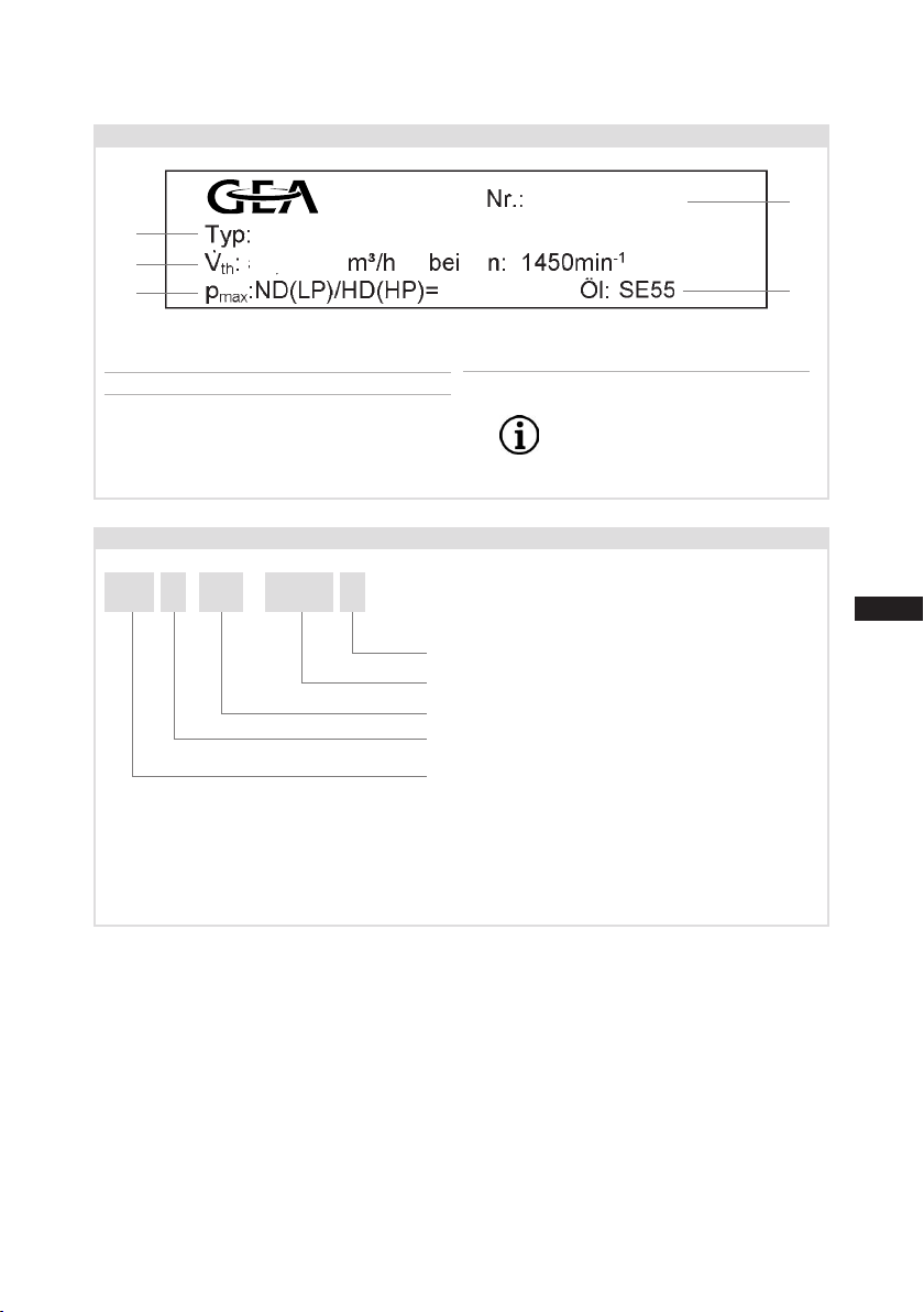
The compressors are factory-lled with the following oil type:
- for R134a, R404A/R507, R407C FUCHS Reniso Triton SE 55
- for R22 FUCHS Reniso SP 46
Compressors with ester oil charge (FUCHS Reniso Triton SE 55) are marked with an X in the type
designation (e.g. FKX30/325 N).
3.1 Refrigerants
• HFKW / HFC: R134a, R404A/R507, R407C
• (H)FCKW / (H)CFC: R22
3.2 Oil charge
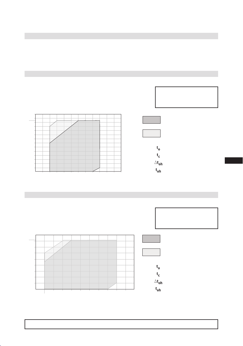
ATTENTION Compressor operation is possible within the limits of application
showninthediagrams.Pleasenotethesignicanceoftheshaded
areas. The limits of application must be observed. Thresholds
should not be selected as design or continuous operating points.
- Max. permissible discharge end temperature: 140°C
- Max. permissible ambient temperature: 100°C
-Max.permissibleswitchingfrequency:12x/h
-A minimum running time of 2 min. at equilibrium (continuous
operation) must be achieved.
Avoid continuous operation near the threshold. Should the com-
pressor happen to be used near the thresholds, we recommend the
useofathermalprotectionthermostat(Accessories,Chap.7).
When operating in the vacuum range, there is a danger of air en-
tering on the suction side. This can cause chemical reactions, a
pressure rise in the condenser and an elevated compressed-gas
temperature. Prevent the ingress of air at all costs!
3.3 Limits of application
INFO For recharging, we recommend the above oil types. Alternatives are:
see lubricants table, Chapter 6.6.

9
D
GB
F
I
Tr
Ru
09705-01.2018-DGbFITrRu
3|Areas of application
Designforotherrangesonrequest
Max. permissible
operating pressure high-
pressureside(HP):28bar
Unrestricted
application range
Unrestricted
application range
Reduced suction gas
temperature
Reduced suction gas
temperature
Evaporation temperature (°C)
Condensing temperature (°C)
Suction gas superheat (K)
Suction gas temperature (°C)
Fig. 4
Fig. 5
20
30
50
70
80
-20 -10 10
020 30 t (°C)
o
t (°C)
c
82
-30
40
60
90
t + 25 °C
oh
<
?
t
oh
20 K
R134a
20
30
50
-20 -10 10
020 t (°C)
o
t (°C)
c
61
-30
40
60
-25
<
?
toh 20 K
t + 25 °C
oh
R407C
3.4.1LimitsofapplicationR134a(NandKversions)
3.4 N and K versions
Models available:
•FKX30/235 N • FKX30/275 N • FKX30/325 N
•FKX30/235 K • FKX30/275 K • FKX30/325 K
Permissible rotation speeds:
N-Design: 500 - 3000 ¹/rpm (max rotation speed 3500 rpm)
K-Design: 500 - 3500 ¹/rpm
3.4.2LimitsofapplicationR407C(NandKversions)
Permissible rotation speeds:
N-Design: 500 - 2600 ¹/rpm
K-Design: 500 - 3500 ¹/rpm
Max. permissible
operating pressure high-
pressureside(HP):28bar

10
D
GB
F
I
Tr
Ru
09705-01.2018-DGbFITrRu
3|Areas of application
3.5 TK version
Models available:
• FK30/235 TK • FK30/275 TK • FK30/325 TK
• FKX30/235 TK • FKX30/275 TK • FKX30/325 TK
3.5.1LimitsofapplicationR404A/R507(TKversion)
3.5.2LimitsofapplicationR22(TKversion)
Permissible rotation speeds:
TK design: 500 – 2600 ¹/rpm
Permissible rotation speeds:
TK design: 500 – 2600 ¹/rpm
FK
10
0
-10
-20
-30
-40
-50
20
30
40
50
60
70
t (°C)
o
t (°C)
c
Dtoh<20K
t +20°C
oh
58
-45
R404A/R507
R404A/R507 TK
t
c
t
0
toh
Dt
oh
Verdampfungstemperatur (°C)
Verflüssigungstemperatur (°C)
Sauggasüberhitzung (K)
Sauggastemperatur (°C)
Uneingeschränkter
Anwendungsbereich
reduzierte Sauggastemperatur
FK
R22
t
c
t
0
toh
Dt
oh
Verdampfungstemperatur (°C)
Verflüssigungstemperatur (°C)
Sauggasüberhitzung (K)
Sauggastemperatur (°C)
Uneingeschränkter
Anwendungsbereich
reduzierte Sauggastemperatur
R22 TK
10
0
-10
-20
-30
-40
-50
20
30
40
50
60
70
t (°C)
o
t (°C)
c
Dtoh<20K
t +25°C
oh
66
-45
Max. permissible
operatingpressure(g)high-
pressureside(HP):28bar
Unrestricted
application range
Reduced suction gas
temperature
Evaporation temperature (°C)
Condensing temperaturee (°C)
Suction gas superheat (K)
Suction gas temperature (°C)
Fig. 6
R404A/R507
R22
Max. permissible
operatingpressure(g)high-
pressureside(HP):28bar
Unrestricted
application range
Reduced suction gas
temperature
Evaporation temperature (°C)
Condensing temperaturee (°C)
Suction gas superheat (K)
Suction gas temperature (°C)
Designforotherrangesonrequest
Fig. 7

11
D
GB
F
I
Tr
Ru
09705-01.2018-DGbFITrRu
A
a
A
a
4|Compressor assembly
4.1 Setting up
4.2 Maximum permissible inclination
Fig. 8
Fig. 9
Fittings (e.g. pipe holders, additional units etc.) on the compressor are
permissible only following consultation with GEA.
Setup on an even surface or frame with sufcient load-bearing capac-
ity. Use all 4 fastening points.
Correct setup of the compressor and mounting of the belt drive are
decisive for running comfort, operating safety and the service life of
the compressor.
In the condition on delivery the compressor is provided with installa-
tion feet (see Fig. 8). Alternatively the compressor can also be bolted
directly, without installation feet, on the substructure.
A
a
A
a
Amax. 30°,
max. 2 minutes
amax. 15°,
continuous
operation
INFO Newcompressorsarefactory-lledwithinertgas.Leavethisser-
vice charge in the compressor for as long as possible and prevent
the ingress of air.
Check the compressor for transport damage before starting any
work.
ATTENTION Poor lubrication can damage the compressor. Respect the stated
values.

12
D
GB
F
I
Tr
Ru
09705-01.2018-DGbFITrRu
4|Compressor assembly
4.3 V-belt drive
4.4 Main bearing load
4.5 Installation of electromagnetic clutch assembly
To prevent the belt drive overloading the compressor main bearing,
ensure that:
The force applied at the force engagement force by the belt
tension (see Fig. 10) must not exceed Fmax = 2750 N.
If the force engagement point shifts forwards (see Fig.10, small
point), the force Fmax reduces as per the following formula:
Fmax zul. = 245 kNmm
(90 mm + L1 [mm])
The following description applies for an electromagnetic clutch secured to a shaft.
To absorb the magnetic eld of the electromagnetic clutch, the front bearing ange has a
snug t Ø 95 f7 (see Fig. 11).
For the installation push the magnetic eld on snugly and fasten with 2 cheese head screws
M6 x 16 (see Fig. 12). Screw tightening torque = 15 Nm.
Further assembly of the electromagnetic clutch according to the clutch manufacturer.
Bearing ange, front
Magnetic eld
Fig. 12
Fmax = 2750 N
(Mbmax = 245 kNmm)
Fmax
L
1
(mm)
Fig. 10
95 f7
Fig. 11
ATTENTION Inappropriately designed belt drives, especially belt knocking
or excessive tensioning forces can cause compressor damage!
Make sure that the drive belt is designed correctly, e.g. by using
tensionersandselectingthebeltproleandthebeltlength.

13
D
GB
F
I
Tr
Ru
09705-01.2018-DGbFITrRu
4|Compressor assembly
4.7 Pipes
Pipes and system components must be clean and dry inside and free of scale, swarf and layers of
rust and phosphate. Only use air-tight parts.
Lay pipes correctly. Suitable vibration compensators must be provided to prevent pipes being
cracked and broken by severe vibrations.
Ensure a proper oil return.
Keep pressure losses to an absolute minimum.
The discharge and suction line valves have stepped internal
diameters, enabling the use of pipes with standard millimetre and
inch dimensions. The depth of pipe insertion will depend on the
dimension.
The connection diameters of the shut-off valves are designed for
maximum compressor output. Therequiredpipecross-section
must be matched to the capacity. The same applies for
non-return valves.
Fig.13: Stepped
internal diameters
4.6 Pipe connections
Valve spindle seal
4.8 Operating the shut-off valves
Before opening or closing the shut-off valve, release the valve spindle seal by approx. ¼ of a turn
counter-clockwise.
After activating the shut-off valve, re-tighten the adjustable valve spindle seal clockwise.
Fig. 14 Fig. 15
Release
Tighten
The required tightening torque for the ange connection is 80 Nm.
ATTENTION Overheating can damage the valve.
Therefore, remove the pipe supports from the valve before
soldering.
Solderonlyusinginertgastoinhibitoxidationproducts(scale).

14
D
GB
F
I
Tr
Ru
09705-01.2018-DGbFITrRu
4|Compressor assembly
4.9 Operating mode of the lockable service connections
Pipe connection
Pipe connection
Fig. 16
Opening the shut-off valve:
Spindle: turn to the left (counter-clockwise) as far as it will go.
—> Shut-off valve fully opened / service connection closed.
The connection is not lockable and is provided for safety devices.
Fig. 17
Opening the service connection
Spindle: Turn 1/2 -1 rotation to the right.
—> Service connection opened / shut-off valve opened.
The connection is not lockable and is provided for safety devices.
Service connection
closed
Connection
closed
Spindle
Connection not lockable
Service connection
open
Spindle Connection
open
Compressor
Compressor
After activating the spindle, generally t the spindle protection cap again and tighten with 14-16 Nm.
This serves as a second sealing feature during operation.
For systems with long pipes and higher degree of contamination, a lter on the suction-side is
recommended. The lter has to be be renewed depending on the degree of contamination (reduced
pressure loss).
4.10Suctionpipelter

15
D
GB
F
I
Tr
Ru
09705-01.2018-DGbFITrRu
5|Commissioning
5.1 Preparations for start-up
5.4 Evacuation
First evacuate the system and then includethe compressor in the evacuation process.
Relieve the compressor pressure.
Open the suction and discharge line valves.
Evacuate the suction and discharge pressure sides using the vacuum pump.
At the end of the evacuation process, the vacuum should be < 1.5 mbar when the pump is switched off.
Repeat the process as often as is required.
The compressor has undergone trials in the factory and all functions have been tested. There are
therefore no special running-in instructions.
Check the compressor for transport damage!
5.3 Leak test
Carry out the leak test on the refrigerating plant in accordance with EN 378-2 or a corresponding
safety standard, while always observing the maximum permissible overpressure for the compressor.
5.2 Pressure strength test
The compressor has been tested in the factory for pressure integrity. If however the entire system is
to be subjected to a pressure integrity test, this should be carried out in accordance with EN 378-2
or a corresponding safety standard without the inclusion of the compressor.
INFO To protect the compressor against inadmissible operating condi-
tions, high-pressure and low-pressure pressostats are mandatory
on the installation side.
DANGER Risk of bursting!
The compressor must only be pressurised using nitrogen (N2).
Never pressurise with oxygen or other gases!
The maximum permissible overpressure of the compressor must
notbeexceededatanytimeduringthetestingprocess(seename
plate data)! Do not mix any refrigerant with the nitrogen as this
could cause the ignition limit to shift into the critical range.

16
D
GB
F
I
Tr
Ru
09705-01.2018-DGbFITrRu
After starting, check the compressor's oil level.
Drive motor in operating condition "High idle".
Compressor run time min. 10 minutes.
The system should have reached operating points.
Check oil level. The oil level must be visible in the sightglass.
5.6 Oil level check
5|Commissioning
Make sure that the suction and discharge line valves are open.
With the compressor switched off, add the liquid refrigerant directly to the condenser or receiver,
breaking the vacuum.
If the refrigerant needs topping up after starting the compressor, it can be topped up in vapour
form on the suction side, or, taking suitable precautions, also in liquid form at the inlet to the
evaporator.
5.5 Refrigerant charge
CAUTION Wear personal protective clothing such as goggles and protective
gloves!
ATTENTION Avoidoverllingthesystemwithrefrigerant!
To avoid shifts in concentration, zeotropic refrigerant blends
mustalwaysbeaddedtotherefrigeratingplantinliquidform.
Donotpourliquidrefrigerantthroughthesuctionlinevalveonthe
compressor.
It is not permissible to mix additives with the oil and refrigerant.
ATTENTION After a compressor is replaced, the oil level must be checked again.
If the level is too high, oil must be drained off (riskofoilimpact,
reduced performance of the air-conditioning system).

17
D
GB
F
I
Tr
Ru
09705-01.2018-DGbFITrRu
5|Commissioning
The compressor shaft is sealed to outside using a shaft seal. The sealing element rotates with the
shaft.
The following is especially important to ensuring fault-free operation:
The complete refrigerant circuit must be correctly executed and clean inside.
Heavy shocks and vibrations to the shaft as well as continuous cyclic operation are to be avoided.
The sealing surfaces can stick together during prolonged downtimes (e.g. winter). Therefore, run
the system every 4 weeks for 10 minutes.
5.8 Avoidingliquidshocks
To avoid liquid shocks, the following points should be observed:
The complete refrigeration plant must be correctly designed and executed.
The capacities of all components must be compatible (particularly evaporator and expansion
valve).
Suction gas superheating at the evaporator output should be at least 7 – 10 K (check setting of
the expansion valve).
The system must reach a state of equilibrium.
Particularly in critical systems (e.g. several evaporator points), suitable measures, e.g. use of
liquid traps, solenoid valve in the liquid line, etc. are recommended.
5.7 Shaft seal
ATTENTION Failure to observe the following instructions can cause loss of
refrigerant and damage to the shaft seal!
INFO The shaft seal seals and lubricates with oil. An oil leakage of
0.05 ml per operating hour is therefore normal. This applies
particularlyduringtherun-inphase(200-300h).
Totrapandcollectleakedoil,theFK40isttedwithaninte-
gratedleakoiltrappingdevicewithoilreservoir(P.6,Fig.1).
ATTENTION Slugging can damage the compressor and cause refrigerant to leak.

18
D
GB
F
I
Tr
Ru
09705-01.2018-DGbFITrRu
Oil change: In principle, an oil change is not mandatory if the system is correctly manufactured
and operated. However, based on decades of experience we recommend that the following oil
change/service work is carried out:
- First oil change during the rst maintenance of the vehicle.
- Then after every 5,000 operating hours, though no more than 3 years, clean the oil strainer
at the same time. If necessary, also empty the oil reservoir at the shaft seal.
Annual checks: Oil level, tightness of the compressor, running noise, pressures, temperatures,
function of the auxiliary equipment check.
6.1 Preparation
6.2 Work to be carried out
6|Maintenance
WARNING Before starting any work on the compressor:
Switch off the compressor and secure it to prevent a restart.
Relieve compressor of system pressure.
Preventairfrominltratingthesystem!
After maintenance has been performed:
Connect safety switch.
Evacuate compressor.
Release switch lock.
Fig. 18
As changing the shaft seal involves opening the refrigerant
circuit, this is recommended only if the seal is losing refriger-
ant. Replacing the shaft seal is described in the spare part
kit concerned.
Emptying the oil reservoir: The oil reservoir can be emptied
very simple without having to dismantle the coupling and/or
belt drive. It is recommended that this is done at the same
time as the air-conditioning maintenance and motor service.
To proceed, detach the oil hose from the bracket, remove the
sealing plug and drain the oil into a collecting vessel. After
emptying, reseal the oil hose and clamp it into the bracket.
Dispose of the used oil in accordance with national
regulations.
6.3 Shaft seal, emptying the oil reservoir

19
D
GB
F
I
Tr
Ru
09705-01.2018-DGbFITrRu
FK30 / ... 235 N
235 TK
275 N
275 TK
325 N
325 TK
235 K
275 K
325 K
Designation Ref. No. Ref. No. Ref. No. Ref. No.
Set of gaskets 80232 80126
Valve plate kit 80240 80242 80241 80010
Set of shaft seals 80123
Oil collector ring 80127
Oil SP 46, 1 Ltr. 02279
Oil SE 55, 1 Ltr. 02282
The valve is maintenance free.
However, constant leakage can occur after blowing off due to abnormal operating conditions. This
leads to reduced performance and increases the compressed gas temperature. In this case check the
valve and replace as necessary.
6.5 Integrated decompression valve(onlyFK30/275+325)
Only use genuine GEA spare parts!
6.4 Recommended spare parts
6.7 Decommissioning
Close the shut-off valve on the compressor. Drain the refrigerant (it must not be discharged directly
into the environment) and dispose of it according to the regulations. When the compressor is depres-
surised, undo the fastening screws of the shut-off valves. Remove the compressor using an appropri-
ate hoist. Dispose of the oil inside in accordance with the valid national regulations.
6|Maintenance
6.6 Extract from the lubricants table
The oil type charged as standard in the factory is marked on the name plate. This oil type should be
used as a preference. Alternatives are stated in the extract from our lubricants table below.
Refrigerant GEA standard oil grade Recommended alternatives
HFC
(e.g. R134a, R407,
R 404A)
Fuchs Reniso Triton SE 55
(see also chap. 6.3)
Fuchs SEZ 32/68/80
Esso/Mobil EAL Arctic 46
HCFC (e.g. R22) Fuchs Reniso SP 46
(see also chap. 6.3)
BP Energol LPT 46
Sunoco Suniso 3.5GS
Texaco Capella WF 46

20
D
GB
F
I
Tr
Ru
09705-01.2018-DGbFITrRu
7|Accessories
A screw-in option is provided for the sensor element on the hot gas side of the compressor
housing (see Chap. 9). Connect the thermal protection thermostat in series with the control line.
Technical Data:
Switching voltage max. : 24 V DC
Switching current max. : 2.5 A at 24 V DC
Switch-off temperature : 145 °C ± 5 K
Switch-on temperature : approx. 115 °C
7.1 Thermal protection thermostat(Art.-No.07595)
This manual suits for next models
18
Table of contents
Other GEA Bock Air Compressor manuals

GEA Bock
GEA Bock HGZ7 Series User manual

GEA Bock
GEA Bock HA22e User manual

GEA Bock
GEA Bock HA12P User manual

GEA Bock
GEA Bock HG66e Series User manual

GEA Bock
GEA Bock HG34e A Series User manual

GEA Bock
GEA Bock HA6 User manual

GEA Bock
GEA Bock HG22e Series User manual

GEA Bock
GEA Bock HGX44e CO2 Series User manual

GEA Bock
GEA Bock EX-HG66e Series User manual

GEA Bock
GEA Bock EX-HG44e Series User manual