Awoco RH-WQ Island Mounted Series User manual

Range Hood
OWNER'S MANUAL
RH-WQ Island Mounted Series


3
Table of Contents
Important Safety Instructions 3
Installation Preparations 5
Duct Venting and Accessories 5
Tools Needed 5
Venting Requirements 5
Venting System Setup 7
Duct Run Calculation Chart 8
Electrical Requirement 9
Installation 10
Test Before Installing 10
Prepare the Location 10
Installing the Range Hood 11
Connecting the Vent System 11
Electrical Connection 11
InstallingtheBaeFilters 11
Completing the Installation 11
Range Hood Use 12
Range Hood Control Panel 12
Range Hood Care 13
Clean the Exterior Surfaces 13
CleanorReplacetheBaeFilters 13
Replace the LED Lamps 13
Range Hood Troubleshooting 14
Warranty 15

4
IMPORTANT SAFETY INSTRUCTIONS
Please read all instructions carefully before
proceedingfurthertopreventtheriskofre,electric
shock,personalinjuryordamagetotherange
hood. This manual provides a general insight on
the installation and may not include solutions for all
possible issues that may occur.
Important: Read and save these instructions.
Incaseofthismanualdestroyedorlost,please
visit https://www.awoco.com and download a digital
version.
WARNING
TO REDUCE THE RISK OF FIRE, ELECTRIC
SHOCK OR PERSONAL INJURY, PLEASE
READ THE FOLLOWING CAREFULLY BEFORE
ATTEMPTING TO ASSEMBLE, INSTALL,
OPERATE OR MAINTAIN THE RANGE HOOD:
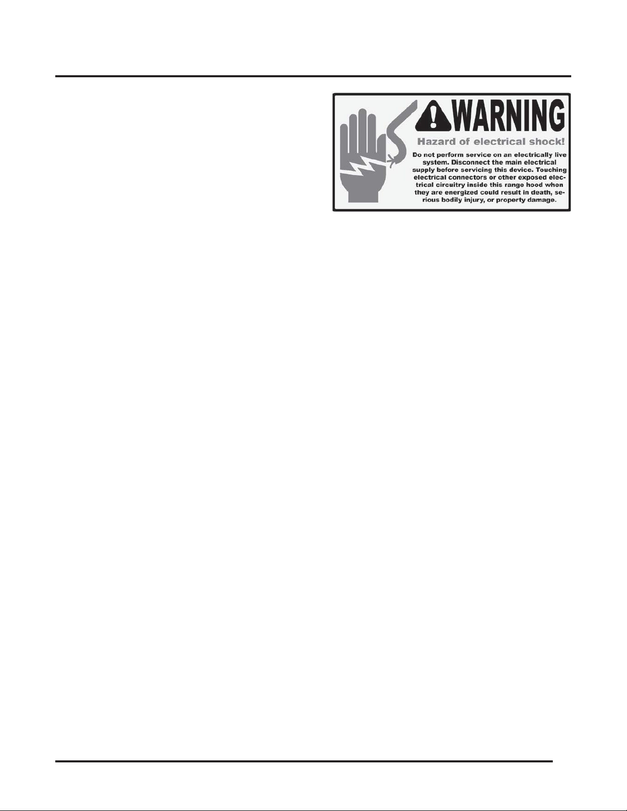
• Alwaysdisconnect,lockandtagthepower
source before installing or servicing the range
hood.Failuretodosomayresultinre,shockor
seriousinjury.
• Installation and eletrical wiring must be done
byqualiedtechnician(s)inaccordancewithall
applicablecodesandstandards,includingre-
rated construction.
• Whencuttingordrillingintowallsorceilings,
please be careful not to damage any eletrical
wirings and other hidden utilities.
• Verify and ensure the rated voltage and
frequency of the range hood is in compliance
with the nearby power source.
• Always unplug the range hood from the power
source before cleaning it.
• Use the range hood only as directed in this
manual. Do not use it to vent hazardous or
explosive materials or vapors.
• Cleanthebaeltersregularlytopreventit
becomeblockedorclogged.Goodairowis
essential for the range hood to work propoerly.
• Donotinstall,repairorreplaceanypartsofthe
range hood unless you are instructed to do so by
the manufacturer.
• Do not tamper with or modify the PCB.
• This range hood model requires a duct to vent
the air outside. Do not vent the air into spaces
withinwalls,ceiliings,attics,crawlspacesor
garages.
TO REDUCE THE RISK OF A RANGE TOP
GREASE FIRE:
• Never leave surface units unattended at high
settings. Boilovers cause smoking and greasy
spillovers that may ignite. Heat oils slowly on low
or medium settings.
• Always turn the hood ON when cooking at
highheatorwhenambeingfood(i.e.Crepes
Suzette,CherriesJubilee,PeppercornBeef
Flambé).
• Clean ventilating fans frequently. Grease should
notbeallowedtoaccumulateonthefanorlter.
• Use proper pan sizes. Always use cookware
appropriate for the size of the surface element.
TO REDUCE THE RISK OF INJURY TO PERSONS
IN THE EVENT OF A RANGE TOP GREASE FIRE:
• SMOTHERFLAMESwithaclose-tting
lid,cookiesheetormetaltray,thenturno
theburner.BECAREFULTOPREVENT
BURNS.Iftheamesdonotgoout
immediately,EVACUATEANDCALLTHEFIRE
DEPARTMENT.
• NEVERPICKUPAFLAMINGPAN-youmaybe
burned.
• DONOTUSEWATER,includingwetdishcloths
or towels - a violent steam explosion may result.
• UseareextinguisherONLYif:
• YouhaveaClassABCextinguisher,andyou
already know how to operate it.
• Thereissmallandcontainedinthearea
where it started.
• Theredepartmentisbeingcalled.
• Youcanghttherewithyourbacktoan
exit.

5
Read and Save These Instructions
IMPORTANT SAFETY INSTRUCTIONS
TO REDUCE THE RISK OF PERSONAL INJURY IN
THE EVENT OF A GAS LEAK:
• Extinguishanyopename.
• DO NOT turn on the lights or any type of appliance.
• Open all doors and windows to disperse the gas.
Ifyoustillsmellthegas,callthegascompany,re
department,or911immediately.

6
INSTALLATION PREPARATIONS
DUCT VENTING AND ACCESSORIES:
• Fornewinstallationoryouroldrangehood
doesn'thaveanexhaustduct,preparetocutthe
openingsthroughthebottomofthecabinet,wall,
topofthecabinetorceiling,denpendingonthe
mounting type. A 6" round semi-rigid aluminim
duct is included.
• If the existing exhaust duct size is not 6" in
diameter,pleasepurchaseaconverter/reducer
/ adapter / elbow.
• Iftheincludedductisnotlongenough,please
purchase additional ducts to extend and reach to
the existing duct connection.
POSSIBLE TOOLS NEEDED:
• JigSaworReciprocatingSaw;
• ScrewdriversorPowerDrill;
• Level;
• MeasuringTape;
• Knife:
• Duct/FoilTape;
• Screws;
• Marker / Pencil.
2 PEOPLE ARE REQUIRED FOR THE
INSTALLATION.
Venting Requirements:
• This range hood requires a venting system
leading to outdoors.
• The venting system must not end in an enclosed
area indoors.
• Use metal vent only. Rigid metal vent is
recommended. Semi-rigid aluminum vent is also
acceptable for easy connection. Plastic vent is
not recommended.
• Always keep the duct clean to ensure proper
airow.
For the most ecient and quiet operation:
• The recommended mounting height is between
a minimum of 24" and a maximum of 30" above
the cooking surface to the bootom of the hood.
• It is recommended to have the venting system
go vertically from the range hood to the roof
using a 6" or bigger round metal / aluminum vent
duct. The vent duct is not included and must be
purchased separately.
• Regardlessthelengthoftheventduct,itssize
should be uniform.
• Use no more than three 90° elbows.
• Make sure there is a minimum of 24" of straight
vent between the elbows if more than 1 elbow is
used.
• Do not install 2 elbows together.
• The length of the venting system and the
number of elbows should be kept to a minimum
toprovideecientperformance.
• Usesilvertaporducttaptosealalljointsinthe
venting system.
• Use caulking silicone to seal exterior wall or roof
opening around the cap.

7
Venting System Setup:
• This range hood is 6" top venting through the
roof or wall.
• Always use 6" round rigid or semi-rigid type
metal/aluminumductstomaximizeairow.
• Observe and determind the location for the
venting route from the hood to the outdoors.
• Astraight,shortventrunwillallowthehoodto
performmoreeciently.
• Fastenallconnectionswithsheetmetalscrews
andtapealljointswithcertiedSilverTapeor
Duct Tape.
• Use caulking to seal the roof or wall opening
around the cap.
Vertical Venting Roof Exhaust
Horizontal Venting Wall Exhaust
Measure and estimate the following gures
before installation:
• The distance between the countertop / stove to
the bottom of the range hood.
• The height of hood and duct.
IMPORTANT!
• Use the Duct Run Calculation Chart to
calculate the total available duct run when using
elbows,transitionsandcaps.
• Always keep the number of transitions and turns
minimum.
• Iflongductrunisneeded,increasetheductsize
from 6" to 7" or 8".
• Ifareducerisneeded,usealongreducer
instead of a pancake reducer and install it as far
away from the range hood as possible. Reducing
the duct size will restrict and decrease the speed
oftheairowandhenselowertherangehood's
performance.
• Iftransitionsorturnsareneeded,installthemas
far away from the range hood as possible and
keep the distance between the 2 as far apart as
possible.
INSTALLATION PREPARATIONS
Range Hood
Roof Cap
Range Hood
Extension
Covers
Min. 24", Max. 30".
Recommended 27"
Stove Top
Roof
Ceiling
Side Wall Cap Ceiling

8
Duct Run Calculation Chart
Recommended Maximum Straight Duct Run 6" round duct 50 ft
Vent Piece Deduction Quantity Used
Each 90º elbow used 9 ft x() =()ft
Each 45º elbow used 5 ft x() =()ft
Side wall cap with damper 0 ft x() =()ft
Roof cap 0 ft x() =()ft
Total Vent Piece Deduction =()ft
Recommended Maximum Straight Duct Run Total Vent Piece Deduction Total Available Duct Run
50 ft - ( ) ft = ( ) ft
Example:
Oneroofcap,two90ºelbow,andone45ºelbowused:0ft+9ftx2+5ft=23ftused.
Total Available Duct Run = 50 ft - 23 ft = 27 ft.
INSTALLATION PREPARATIONS
• The minimum mounting height should be no
less than 24" and the maximum mounting height
should be no more than 30".
• Also refer to the owner's manual of the stove
top for the height clearance requirement and the
recommended mounting height above the range.
Note
• It is important to install the range hood at the
proper mounting height. Hoods mounted too
lowcouldresultinheatdamageandrehazard
while hoods mounted too high will be out of
reach and hense reduce its performance and
eciency.
Minimum Duct Size:
• Round: 6" minimum.

9
INSTALLATION PREPARATIONS
IMPORTANT!
Observe all governing codes and ordinances.
It is the customer's responsibility:
• Tocontactaqualiedelectricalinstaller;
• To ensure that the electrical installation is in
compliance with applicable codes and standards.
Electrical Requirements:
• A120V,60Hz.,AConly,15Afusedelectrical
circuit is required.
• Wire sizes and connections must conform with
the power rating of the range hood and all
applicable codes and standards.
• DO NOT have a fuse in the neutral or ground
circuit.
• The 3-prong outlet should be grounded. If the
powercordplugisnotused,thepowercord’s
green wire should be connected to ground.
Checkwithaqualiedelectricianifyouarenot
sure that the range hood is properly grounded.
• DO NOT ground to a gas pipe.
• The range hood must be connected with copper
wire/plug only.
• The range hood should be connected directly
tothefuseddisconnectbox(orcircuitbreaker)
throughexiblearmoredornon-metallic
sheathed copper cable. ETL listed strain relief
must be provided at each end of the power
supply cable.

10
INSTALLATION
INSTALLATION INSTRUCTIONS
CAUTION!
Wear gloves to protect against sharp edges.
IMPORTANT!
PLEASE FOLLOW THESE INSTRUCTIONS
TO TEST THE RANGE HOOD BEFORE
INSTALLATION FOR ANY DEFECTS OR
SHIPPING DAMAGE:
• Remove the range hood and accessories from
the package carefully.
• Place the Hood Unit and the Blower Unit on a
atstablesurface,removethebaelterand
check for any dent or damage on the range hood
body.
• Remove the loosen parts if there's any.
• Plug the range hood into a 120V AC power
source.TouchtheSpeedSelection(-)or(+)
button to turn it on.
• Check each speed variation and pay attention
to the noise level to make sure there isn't any
unusual noise besides it coming from the wind
blowing. Press the Light Button to check the
lights.
• Verifyallfunctions,asinstructedinPage12,are
operational.
• Refer to Range Hood Troubleshooting in Page
14 for general issues and solutions.
• Thewhiteproctivelmonthebaeltermust
be removed before using the range hood.
• If the range hood you receive is damaged or
defective,pleasecontactthesellerimmediately.
Do not try to install and use the damaged or
defective unit.
IMPORTANT!
TOAVOIDDAMAGETOTHERANGEHOOD,DO
NOT LET DEBRIS ENTER THE VENT OPENING.
CAUTION!
IFMOVINGTHECOOKINGRANGEIS
NECESSARYTOINSTALLTHERANGEHOOD:
• For electric ranges, unplug the power rst before moving it.
• For gas ranges, shut o the gas valve before moving it.
Observe and prepare the location
• Determine the location for the range hood. Refer
to instructions in Page 7 for clearance guidiance.
• Determine which venting method to use: roof or
wall.
• Purchaseanyneccessaryaccessories,suchas
duct,elbow,reducer,damper,ducttape,screws
etc.,fromthehardwarestore.
• Useastubndertolocateandmarkthestuds
inside the wall.
• Beforebeginningtheinstallation,makesure
there is proper clearance within the ceiling or
wall for the exhaust vent.
Installing the Range Hood
Note
• The ceiling must be able to hold at least 265 lbs
of weight.
• The ceiling must be at least 1-1/4" thick if the
range hood's top mounting plate is to be installed
directly to the ceiling.
• It is recommended to build a stud frame above
the ceiling and install the range hood to the
studs for a more secure installation.
The following steps requires 2 or more people:
• Determind the location and height to mount the
range hood. The range hood should be aligned
with the stove.
• Mark the perimeter of the top of the duct cover
on the ceiling.
• Drillahole,whichis6-3/4"indiameter,inthe
center of the perimeter in the ceiling for the 6"
duct access.
• Align the mounting plate with the perimeter
and drill 12 holes in the ceiling. Make sure the
electrical box opening on the mounting plate is

11
INSTALLATION
not blocked by the ceiling.
• Insert the screws into the holes and fasten them
so that the mounting plate is securely mounted
to the ceiling.
• Remove the cover of the electrical box.
• Pull the house wiring through the 6-3/4" hole in
the ceiling and into the electrical box. Secure
the house wiring cables to the mounting plate /
electrical box with appropriate connectors.
• Install the inner duct cover and outer duct cover
to the mounting frame.
• Install the top exhaust to the range hood.
Connect the top exhaust to a 6" round duct and
seal the connection.
• Lead the other end of the duct through the
mounting frame and the hole in the ceiling.
• Install the range hood to the bottom of the
mounting frame.
CAUTION
Make sure the range hood is securely mounted
before releasing.
• Connect the free end of the duct to the roof / wall
cap.
Electrical Connection
• This range hood comes with a power cord with
a 3-prong plug. Connect the power cord to a
designated grounded standard 110V outlet.
WARNING
Electrical Shock Hazard
Disconnect power before servicing
• In case of a direct connection to the house wiring
ispreferred,dothefollowing:
• Disconnect the power.
• Cut o the plug from the power cord.
• Connect the wires from the power cord to the wires from
the house wiring using UL listed wire connectors.
• Store the excess wires in the wiring box.
• Reconnect the power.
Installing the Bae Filters
• Peelotheprotectivecoverfromthebaelters
if there's any.
• Alignthebaelterswiththerangehoodand
install them from left to right.
Completing the Installation
Turn blower ON in the control panel. Check all lights
and fan operations.

12
Range Hood Control Panel
A. Remote Control Sensor
• The Remote Control Sensor receives infrared
(IR)signalfromtheremotecontrol.
• The maximum distance for IR data transmission
is 10 feet and requires direct line of sight.
• The transmission distance may vary depending on the room
temperature and the condition of the battery in the remote
control.
B. Delayed Auto Shut-O
• Whenthehoodisoperatinginanyspeed,touch
the (B) Delayed Auto Shuto button once will
activate the Delayed Auto Shuto function.
• Touch the (I) Speed Selection (-) or (J) Speed
Selection (+) button to adjusttheperiodofthe
countdown timer.
• The timer can be adjusted between 1 minute minimum and 15
minutes maximum.
• The (D) Delayed Auto Shuto Indicator will be illuminated in the
LCD display once the timer is set and counting.
• The timer will start immediately once it's set. When it reaches 0,
the blowers will be shut o automatically.
C. Light
• Touch the (C) Light button once and the lamps
will turn on.
• Touch the (C) Light button again and the lamps
willturno.
• The Light button operates independently from
the (K) Power button. It works even when the
range hood is not turned on.
• Alwaysturnothelampsbeforepoweringothe
range hood or activating the Delayed Auto Shut-
Ofunction.
D. Delayed Auto Shut-O Indicator
• The (D) Delayed Auto Shuto Indicator will be
illuminated in the LCD display once the timer is
set and counting.
E. Light Indicator
• The (E) Light Indicator will be illuminated in the
LCD display once the lamps are turned on.
F. Clock / Timer Display
• When the Delayed Auto Shut-O function is not
activated,the(F) Clock / Timer Display will show
the current time of the day.
• THECLOCKCANONLYBESETWHILETHE
BLOWERISOFF.TosettheClock:
• Touch the (B) Delayed Auto Shuto button once. The hour
indicator will be ashing.
• Touch the Speed Selection (-) or (+) button to adjust to the
desired hours.
• When done setting the hour, touch the (B) Delayed Auto
Shuto button again. The minute indicator will be ashing.
• Touch the Speed Selection (-) or (+) button to adjust to the
desired minutes.
• When done setting the minutes, touch the (B) Delayed Auto
Shuto button to conrm all settings.
• Touch the (C) Light button to check and validate the time.
• When the (B) Delayed Auto Shuto fuction
isactivatedwhiletheblowerisrunning,a
countdown timer will show up in the (F) Clock /
Timer Display.
G. Blower Indicator
• The (G) Blower Indicator will be illuminated in
the LCD display once the range hood is turned
on and a blower speed is selected.
H. Power Indicator
• The (H) Power Indicator will be illuminated in the
LCD display once the range hood is turned on.
I. & J. Speed Selection (-) (+)
• Whiletherangehoodiso:
• Touch the (I) Speed Selection (-) button to start from the highest
speed.
• Touch the (J) Speed Selection (+) button to start from the lowest
speed.
• Touch (-) or (+) again to change the blower speed as indicated
in the LCD display, or until the desired speed is reached.
K. Power O
• Touch the (K) Power O button once and the
rangehoodwillbeshutoimmediately.
WARNING
Read all instrutions and warnings before using
the hood.
• DO NOT use the hood when there are no safety
grillsandlters.
• NEVERdisposecigaretteashes,ignitable
substances,oranyforeignobjectsintoblowers.
• NEVER leave the cooking appliances
unattended.Whenfrying,theoilinthepancan
Range Hood Use
A. Remote Control Sensor
B. Delayed Auto Shut-O
C. Light
D. Delayed Auto Shut-O Indicator
E. Light Indicator
F. Clock / Timer Display
G. Blower Indicator
H. Power Indicator
I. Speed Selection (-)
J. Speed Selection (+)
K. Power O

13
easilyoverheatandcatchonre.Theriskof
self-combustion is higher when the oil has been
used several times.
• NEVERcookon“open”amesunderthe
range hood. Check deep-fryers during use:
Superheatedoilmaybeammable.
Cleaning
WARNING
• Toreducetheriskofelectricalshock,DONOT
clean the hood while it's operating.
• Never put your hands into the area housing the
fan when the fan is operating.
Cleaning the Exterior Surfaces:
IMPORTANT
To avoid damage to the exterior surfaces:
• DO NOT use corrosive or abrasive detergent.
• DONOTusesteelwool,scoringpadorsteel
brushes. Use a paper towel or soft cloth or
nonabrasive sponge instead.
• DONOTusesaltsolutions,disinfectants,
bleaches or cleaning compound that contains
harmful chemicals.
Cleaning Method:
• Noncorrosive or nonabrasive liquid detergent
soap or all-purpose liquid cleanser.
• Wipe the surfaces with a damp paper towel or
soft cloth or nonabrasive sponge.
• Rinse with clean water.
• Wip dry with dry towel or cloth.
Note
• The nonabrasive stainless steel polisher can
be applied when done cleaning to retain the
stainless luster and grain.
• Always follow the instrunction of the polisher.
Cleaning the Stainless Steel Bae Filters:
• Pull the spring release handle and remove the
lterbypullingitdown.
• Washthelterinthetoprackofthedishwasher
or with warm soapy solution manually.
• Lettheltersdrythoroughly.
• Make sure the spring release handle is toward
thefront,alignandinsertthelter.
• Pullthespringreleasehandleandpushthelter
into position.
• Release the handle.
• Repeatthestepsfortheremaininglters.
Replacing the Filters:
• Replacethebaeltersimmediatelyshould
they become worn out due to aging or prolonged
usage.
Replacing the LED Lamps:
WARNING
Electrical Shock Hazard
Disconnect power before servicing
Wear gloves to protect against sharp edges
• Thisrangehooduses12V,3WLED.
• Unplugtherangehood,orturnothebreaker.
• RemovetheBaeFilteradjacenttotheLamp.
• Reach into the Hood Unit and push the Lamp
out from the inside of the Hood Unit.
• Disconnect the wires.
• Connect the wires to the new Lamp.
• Align and put the new Lamp back into position.
• Press the edge of the new Lamp until it touches
the bottom of the Hood Unit.
• PuttheBaeFilterbackintoplace.
• Plugintherangehood,orturnonthebreaker.
• Check if the new Lamp is working properly.
Range Hood Care
Reach into the Hood
Push the lamp out

14
Before Calling for Service
Issue Possible Cause / Solution
The range hood doesn't turn on
• Check if the range hood is plugged in. Make sure that all
poweristurnedON,thefuseisn'tblownandallelectrical
wirings are properly connected.
The range hood turns on but
the LED light doesn't
• Replace the defective LED assembly. Refer to Range
Hood Care section for instructions.
The range hood vibrates when
the blower is on
• Check and tighten the mounting screws to secure the
hood to the cabinet or wall properly.
The blower or fan seems weak
• Check that the duct size used is at least 6”. Range hood
WILLNOTfunctionecientlywithinsucientductsize.
• Checkiftheductiscloggedorthedamper(half-circular
apper)isnotinstalledcorrectlyoropeningproperly.A
tight mesh on a side wall cap might also cause restriction
totheairow.
The lights work but the blower
is not spinning at all or is rattling
• Theblowermightbejammedorscrapingthebottomdue
to shipping damage.
• Disconnectthepowercord,removethefangrillandthe
fanblade,mightseethefanbladeor/andmotorisnot
intheproperposition(osetfromthecenter).Trytox/
adjustitorpleasecontactusimmediately.
The hood is not venting out
properly
• Make sure the distance between the stove top and the
bottom of the hood is within recommended 24” and 30” in
distance.*Duetodierentceilingheightcongurations,
the recommended height may not be applicable.
• Reduce the number of elbows and length of duct work.
Checkifalljointsareproperlyconnected,tapedand
sealed.
• Make sure the power is on high speed for heavy cooking.
Range Hood Troubleshooting

15
This product is warranted for a limited period of ONE
YEAR Parts and Labor, begins from the date of
purchase.
This limited warranty is applied to the original retail
purchaser and valid only for products purchased
for home use in the continental United States of
America.
This limited warranty is non-transferable and does
not extend to the subsequent owners of this product.
Anyapplicableimpliedwarranties,includingthe
warrantyofmerchantability,arelimitedinduration
to a period of express warranty as provided herein
beginning with the date of original purchase at retail
and,nowarranties,whetherexpressorimplied,shall
apply to this product thereafter.
In the event of the product fail to work properly
due to a defect in manufacturing materials or
workmanship under normal home use, during the
warranty period mentioned above, subject to the
conditions and limitations set forth below, Awoco
will, at our options, either repair or replace any
part of our products proven defective by reason
of improper materials or workmanship:
• Proof of original retail purchase is required
to receive warranty service within the limited
warranty period.
• Repair parts or replacement products will
beprovidedbyAwoco,freeofcharge,onan
exchangebasis,andwillbeeithernewor
reconditioned.
• The consumer is responsible for all shipping
costs.
This Limited Warranty Does Not Cover:
• Consumablepartssuchaslightbulbs,stainless
steelbaelters.
• Thenaturalwearofnish,andweardueto
impropermaintenance,useofcorrosiveand
abrasivecleaningproducts,pads,andoven
cleaner products.
• Chips,dentsorcracksontheproductcausedby
transportation and handling.
• Damageofproductcausedbyaccidents,pests
andvermin,lightning,wind,re,oodsoractsof
God.
• Damage of product caused by unauthorized
modicationoralteration,orifitisusedforother
thantheintendedpurpose,oranywaterleakage
where the unit was not installed properly.
• Damage of product caused by incorrect electrical
wiring,commercialorinductrialuse,oruseof
any cleaning products not recommended in this
manual.
• Damageofproductduetoproductmisuse,
abuse,improperinstallation,unauthorizedrepair
or maintenance.
• Any loss of properties or any costs associated
withremoving,servicing,installing,or
determining the source of problems with our
products.
To Receive Warranty Service:
• Contact the seller or distributor from which you
purchasetheproduct.Pleaseconrmtheterms
ofyourdealer’sordistributor’spoliciespriorto
contacting. Or contact us directly.
• Providetheproductidenticationinformation,
suchasmodelnumberandlotnumber,and
proof of original purchase.
• Decribe the issue you are experiencing in detail.
Product Support and Additional Information:
If you need assistance using your product or you
would like to start the warranty service:
• Contactusat1-888-412-3428,between9AM
and5PM,Monday-Friday,PacicTime.
Or
• Contact us at https://www.awoco.com/contact-
us.
Warranty

Website: www.awoco.com Customer Support: 1-888-412-3428
Table of contents
Other Awoco Ventilation Hood manuals

Awoco
Awoco RH-BQ User manual

Awoco
Awoco SP-06 User manual

Awoco
Awoco 6" Height Under Cabinet Series User manual

Awoco
Awoco RH-IT Split Insert Series User manual

Awoco
Awoco RH-UC085 Troubleshooting guide

Awoco
Awoco UGA S0176F1H1 User manual

Awoco
Awoco RH-SP06 Troubleshooting guide

Awoco
Awoco Super Quiet Split Series Troubleshooting guide

Awoco
Awoco RH-R06-G30 User manual

Awoco
Awoco RH-WT-36 User manual
Popular Ventilation Hood manuals by other brands

Midea
Midea MHAA90BL Instruction

Electrolux
Electrolux EFF55550D user manual

Broan
Broan BCSQ130SS Installation use and care manual

AEG
AEG DD 8415 user manual

Whirlpool
Whirlpool WVW51UC0LS Installation Instructions and Use & Care Guide

villavent
villavent 480-17 installation, user and maintenance instructions