Axess sepro ROBOTIQUE User manual

USER MANUAL
Robots' Software Version 2.0 |->

S:\documentation\Docs\Axess\Utilisation\gb\EC_V2\Page_garde.fm
© Copyright SEPRO ROBOTIQUE, 2006, all rights reserved.
The contents of this document remains the industrial, intellectual and commercial property of SEPRO
ROBOTIQUE. According to L122-4 of the intellectual property code, any presentation or reproduction made
without the author’s or lawful owner’s permission is unlawful and may lead to penal sanctions.
The customer therefore agrees to only use the information and data contained in this document for his own needs,
within his company, and not to sell any of it, either directly or indirectly. Any reproduction used for
communicating to a third party, even if free, is forbidden.
This document is given to the customer when the ordered product is delivered. SEPRO ROBOTIQUE may change
it afterwards without warning. It is therefore the customer’s duty to contact SEPRO ROBOTIQUE’s technical
customer assistance department for any updates.
Logos definitions :
Warning, risk
Sepro robotique inventions
What to do ?
Document evolutions
Handy hints
Example
New function available
with the software version
marked
?

Axess Sepro User Manual
V2.0 |->
DD0000116802
i
13.2.06
CONTENTS
I - SAFETY INSTRUCTIONS . . . . . . . . . . . . . . . . . . . . . . . . . . . . . . . . . . . . . . . . . . . . . . . . . 1
I - 1. Emergency stops . . . . . . . . . . . . . . . . . . . . . . . . . . . . . . . . . . . . . . . . . . . . . . . . . . . . . 1
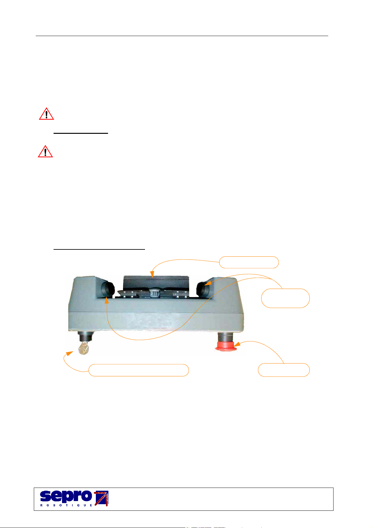
I - 2. The pendant’s safety devices . . . . . . . . . . . . . . . . . . . . . . . . . . . . . . . . . . . . . . . . . . . 1
I - 2. 1. The safeguard override key . . . . . . . . . . . . . . . . . . . . . . . . . . . . . . . . . . . . . . . 1
I - 2. 2. Working with the pendant out of its holder . . . . . . . . . . . . . . . . . . . . . . . . . . . 1
I - 3. Peripheral units and safeguards. . . . . . . . . . . . . . . . . . . . . . . . . . . . . . . . . . . . . . . . . . 2
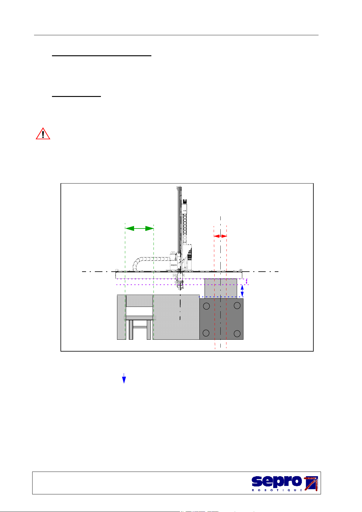
I - 4. The work zones . . . . . . . . . . . . . . . . . . . . . . . . . . . . . . . . . . . . . . . . . . . . . . . . . . . . . . 2
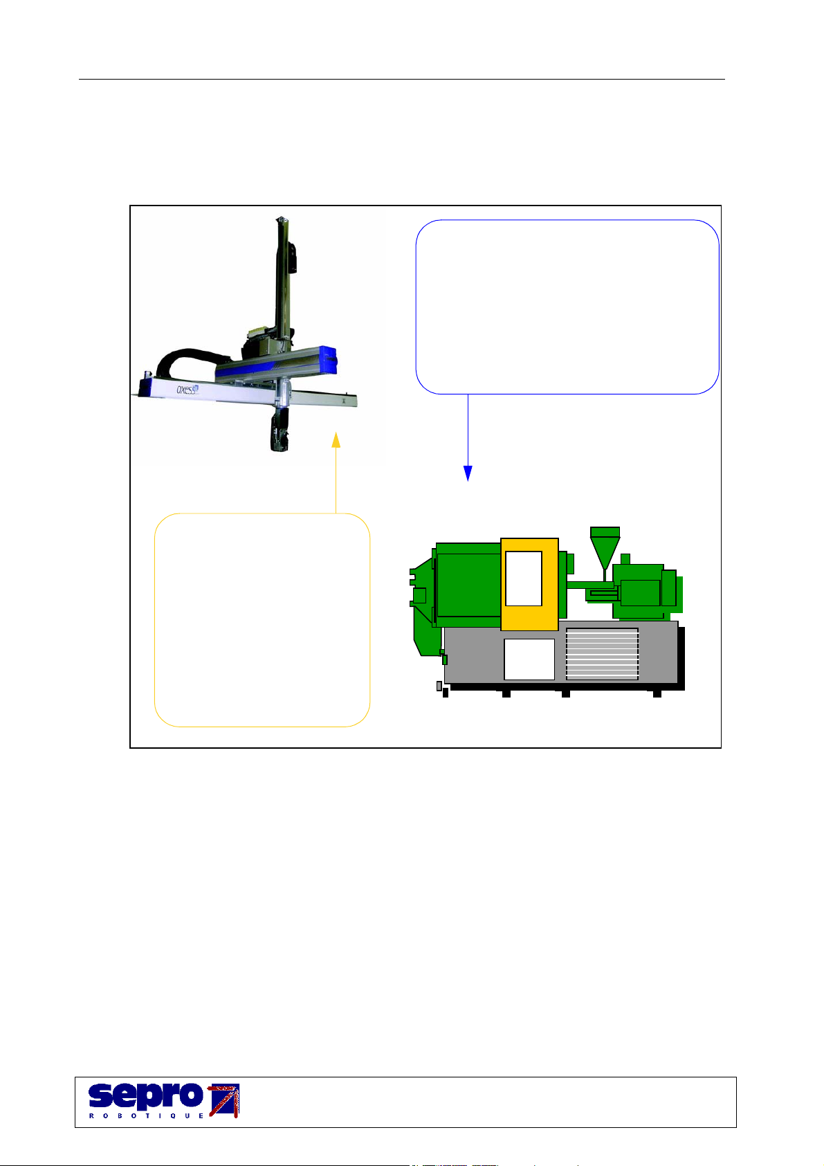
II - ROBOT / IMM DIALOGUE . . . . . . . . . . . . . . . . . . . . . . . . . . . . . . . . . . . . . . . . . . . . . . . 3
III - QUICK REFERENCE . . . . . . . . . . . . . . . . . . . . . . . . . . . . . . . . . . . . . . . . . . . . . . . . . . . 4
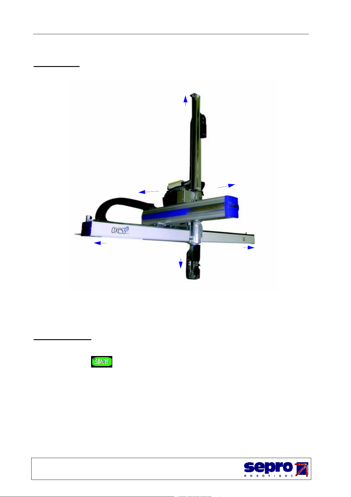
III - 1. The axes . . . . . . . . . . . . . . . . . . . . . . . . . . . . . . . . . . . . . . . . . . . . . . . . . . . . . . . . . . 4
III - 2. Powering up . . . . . . . . . . . . . . . . . . . . . . . . . . . . . . . . . . . . . . . . . . . . . . . . . . . . . . . 4
III - 3. Navigating . . . . . . . . . . . . . . . . . . . . . . . . . . . . . . . . . . . . . . . . . . . . . . . . . . . . . . . . 5
III - 3. 1. The modes . . . . . . . . . . . . . . . . . . . . . . . . . . . . . . . . . . . . . . . . . . . . . . . . . . . 5
III - 3. 2. The function keys . . . . . . . . . . . . . . . . . . . . . . . . . . . . . . . . . . . . . . . . . . . . . 6
III - 3. 3. Returning to the previous screen. . . . . . . . . . . . . . . . . . . . . . . . . . . . . . . . . . 6
III - 3. 4. Locking the numeric pad .. . . . . . . . . . . . . . . . . . . . . . . . . . . . . . . . . . . . . . . 6
III - 3. 5. Entering a numeric value. . . . . . . . . . . . . . . . . . . . . . . . . . . . . . . . . . . . . . . . 7
III - 3. 6. Entering text . . . . . . . . . . . . . . . . . . . . . . . . . . . . . . . . . . . . . . . . . . . . . . . . . 7
III - 3. 7. Help key . . . . . . . . . . . . . . . . . . . . . . . . . . . . . . . . . . . . . . . . . . . . . . . . . . . . 7
IV - MANUAL MODE . . . . . . . . . . . . . . . . . . . . . . . . . . . . . . . . . . . . . . . . . . . . . . . . . . . . . . . 8
IV - 1. Manually controlling a numeric movement . . . . . . . . . . . . . . . . . . . . . . . . . . . . . . . 9
IV - 1. 1. Moving an axis . . . . . . . . . . . . . . . . . . . . . . . . . . . . . . . . . . . . . . . . . . . . . . . 9
IV - 1. 2. Changing the movement speed - Kv . . . . . . . . . . . . . . . . . . . . . . . . . . . . . . 9
IV - 1. 3. Changing the movement mode . . . . . . . . . . . . . . . . . . . . . . . . . . . . . . . . . . 10
IV - 2. Manually controlling a pneumatic movement . . . . . . . . . . . . . . . . . . . . . . . . . . . . 10
IV - 2. 1. Part grip and release . . . . . . . . . . . . . . . . . . . . . . . . . . . . . . . . . . . . . . . . . . 10
IV - 2. 2. Rotations . . . . . . . . . . . . . . . . . . . . . . . . . . . . . . . . . . . . . . . . . . . . . . . . . . . 11
IV - 3. Enabling a manual movement of the IMM . . . . . . . . . . . . . . . . . . . . . . . . . . . . . . 11
IV - 4. Manually controlling an output . . . . . . . . . . . . . . . . . . . . . . . . . . . . . . . . . . . . . . . 12
IV - 5. Controlling the belt. . . . . . . . . . . . . . . . . . . . . . . . . . . . . . . . . . . . . . . . . . . . . . . . . 12
IV - 6. Teaching the points in manual . . . . . . . . . . . . . . . . . . . . . . . . . . . . . . . . . . . . . . . . 13
V - MOLD CHANGE - TEST MODE . . . . . . . . . . . . . . . . . . . . . . . . . . . . . . . . . . . . . . . . . 14
V - 1. Home page. . . . . . . . . . . . . . . . . . . . . . . . . . . . . . . . . . . . . . . . . . . . . . . . . . . . . . . . 14
V - 2. Selecting a program . . . . . . . . . . . . . . . . . . . . . . . . . . . . . . . . . . . . . . . . . . . . . . . . . 14
V - 2. 1. Selecting a program on the pendant . . . . . . . . . . . . . . . . . . . . . . . . . . . . . . . 14
V - 3. Creating a program . . . . . . . . . . . . . . . . . . . . . . . . . . . . . . . . . . . . . . . . . . . . . . . . . 14
V - 3. 1. Introduction . . . . . . . . . . . . . . . . . . . . . . . . . . . . . . . . . . . . . . . . . . . . . . . . . 14
V - 3. 2. Creating a program from an EPS . . . . . . . . . . . . . . . . . . . . . . . . . . . . . . . . . 15
V - 4. Teaching the points in cycle . . . . . . . . . . . . . . . . . . . . . . . . . . . . . . . . . . . . . . . . . . 17
V - 4. 1. Principle . . . . . . . . . . . . . . . . . . . . . . . . . . . . . . . . . . . . . . . . . . . . . . . . . . . . 17
V - 4. 2. Stacking sequence . . . . . . . . . . . . . . . . . . . . . . . . . . . . . . . . . . . . . . . . . . . . 17
V - 5. Testing the program. . . . . . . . . . . . . . . . . . . . . . . . . . . . . . . . . . . . . . . . . . . . . . . . . 18

Axess Sepro User Manual
V2.0 |->
DD0000116802
ii
13.2.06
V - 6. Home return. . . . . . . . . . . . . . . . . . . . . . . . . . . . . . . . . . . . . . . . . . . . . . . . . . . . . . . 19
V - 6. 1. Simple Home return . . . . . . . . . . . . . . . . . . . . . . . . . . . . . . . . . . . . . . . . . . . 19
V - 6. 2. Total Home return . . . . . . . . . . . . . . . . . . . . . . . . . . . . . . . . . . . . . . . . . . . . 19
VI - PRODUCTION - AUTOMATIC MODE . . . . . . . . . . . . . . . . . . . . . . . . . . . . . . . . . . . 20
VI - 1. Starting production . . . . . . . . . . . . . . . . . . . . . . . . . . . . . . . . . . . . . . . . . . . . . . . . . 20
VI - 2. Operating and Stop modes . . . . . . . . . . . . . . . . . . . . . . . . . . . . . . . . . . . . . . . . . . . 21
VI - 2. 1. Starting the robot and the IMM in automatic mode . . . . . . . . . . . . . . . . . . 21
VI - 2. 2. Production without the robot. . . . . . . . . . . . . . . . . . . . . . . . . . . . . . . . . . . . 21
VI - 2. 3. Requesting an immediate stop . . . . . . . . . . . . . . . . . . . . . . . . . . . . . . . . . . 21
VI - 2. 4. Requesting an end of cycle stop . . . . . . . . . . . . . . . . . . . . . . . . . . . . . . . . . 21
VI - 2. 5. Quality sampling request . . . . . . . . . . . . . . . . . . . . . . . . . . . . . . . . . . . . . . 22
VI - 3. Home page . . . . . . . . . . . . . . . . . . . . . . . . . . . . . . . . . . . . . . . . . . . . . . . . . . . . . . . 22
VII - CYCLE OPTIMIZATION . . . . . . . . . . . . . . . . . . . . . . . . . . . . . . . . . . . . . . . . . . . . . . 23
VII - 1. Introduction. . . . . . . . . . . . . . . . . . . . . . . . . . . . . . . . . . . . . . . . . . . . . . . . . . . . . . 23
VII - 2. Changing the cycle’s parameters . . . . . . . . . . . . . . . . . . . . . . . . . . . . . . . . . . . . . 24
VII - 3. Points. . . . . . . . . . . . . . . . . . . . . . . . . . . . . . . . . . . . . . . . . . . . . . . . . . . . . . . . . . . 24
VII - 4. Time delays. . . . . . . . . . . . . . . . . . . . . . . . . . . . . . . . . . . . . . . . . . . . . . . . . . . . . . 26
VII - 5. Speeds . . . . . . . . . . . . . . . . . . . . . . . . . . . . . . . . . . . . . . . . . . . . . . . . . . . . . . . . . . 27
VII - 6. Tolerances . . . . . . . . . . . . . . . . . . . . . . . . . . . . . . . . . . . . . . . . . . . . . . . . . . . . . . . 28
VII - 7. Stacking and counters . . . . . . . . . . . . . . . . . . . . . . . . . . . . . . . . . . . . . . . . . . . . . . 29
VIII - TROUBLESHOOTING . . . . . . . . . . . . . . . . . . . . . . . . . . . . . . . . . . . . . . . . . . . . . . . . 30
VIII - 1. Introduction . . . . . . . . . . . . . . . . . . . . . . . . . . . . . . . . . . . . . . . . . . . . . . . . . . . . . 30
VIII - 2. Cancelling a fault. . . . . . . . . . . . . . . . . . . . . . . . . . . . . . . . . . . . . . . . . . . . . . . . . 30
VIII - 3. Standard messages. . . . . . . . . . . . . . . . . . . . . . . . . . . . . . . . . . . . . . . . . . . . . . . . 30
VIII - 4. Difficulties related to the part grip . . . . . . . . . . . . . . . . . . . . . . . . . . . . . . . . . . . 31
VIII - 4. 1. Causes and actions . . . . . . . . . . . . . . . . . . . . . . . . . . . . . . . . . . . . . . . . . . 31
VIII - 4. 2. Starting again after a fault . . . . . . . . . . . . . . . . . . . . . . . . . . . . . . . . . . . . 32
VIII - 4. 3. Settings . . . . . . . . . . . . . . . . . . . . . . . . . . . . . . . . . . . . . . . . . . . . . . . . . . . 32
VIII - 5. IMM - robot dialogue . . . . . . . . . . . . . . . . . . . . . . . . . . . . . . . . . . . . . . . . . . . . . 33
VIII - 6. Initializing the axes . . . . . . . . . . . . . . . . . . . . . . . . . . . . . . . . . . . . . . . . . . . . . . . 34
IX - MAINTENANCE FUNCTION . . . . . . . . . . . . . . . . . . . . . . . . . . . . . . . . . . . . . . . . . . . 35
IX - 1. Home page: . . . . . . . . . . . . . . . . . . . . . . . . . . . . . . . . . . . . . . . . . . . . . . . . . . . . . . 35
IX - 2. Fault log book. . . . . . . . . . . . . . . . . . . . . . . . . . . . . . . . . . . . . . . . . . . . . . . . . . . . . 35
IX - 3. Axes’ maintenance . . . . . . . . . . . . . . . . . . . . . . . . . . . . . . . . . . . . . . . . . . . . . . . . . 35
IX - 4. System configuration . . . . . . . . . . . . . . . . . . . . . . . . . . . . . . . . . . . . . . . . . . . . . . . 37
IX - 5. Monitor. . . . . . . . . . . . . . . . . . . . . . . . . . . . . . . . . . . . . . . . . . . . . . . . . . . . . . . . . . 38

I -Safety instructions Axess Sepro User Manual
V2.0 |->
DD0000116802
1
13.2.06
I - SAFETY INSTRUCTIONS
The robot must only be used on an injection machine in a safe environment. Safeguards must be
installed so that the robot’s work zone is inaccessible. Access for operations such as maintenance
or part manipulation by operators must only be carried out after a shut-down procedure or if the
safeguards have been specifically adapted.
A robot which is immobile is not stopped. A robot which is stopped is not shut-down.
I - 1. Emergency stops
An emergency stop does not necessarily cut the pneumatic air supply, which means that:
• the pneumatic movements being executed are finished,
• it is necessary to dump the pressure before intervening on the robot.
When the robot’s emergency stop button is pressed:
• the actuators’ electric power supply is cut. The numeric movements are therefore stopped
brutally.
• the IMM stops.
I - 2. The pendant’s safety devices
I - 2. 1. The safeguard override key
This key authorizes the robot movements in manual mode and in test mode, even if the safeguards
are not installed. When requesting a movement, you must also push one of the 2 push buttons
called enabling devices. The speed of the axes’ movement is reduced.
I - 2. 2. Working with the pendant out of its holder
When the pendant is out of its holder, only the manual and test modes are authorized. Automatic
mode is prohibited.
Enabling
devices
Pendant holder
Emergency stop
Safeguard override key

Axess Sepro User Manual I -Safety instructions
V2.0 |->
DD0000116802
2
13.2.06
I - 3. Peripheral units and safeguards
After any intervention on the peripheral units (conveyor ...) and/or safeguards, you MUST then
check that they are correctly installed and connected. To do this, you may need to refer to the
electrical drawings or to the application’s specific documentation.
I - 4. The work zones
These zones limit the robot movements when it’s in automatic or test mode. The purpose of these
zones is to avoid mechanical interference.
In manual mode, the robot no longer manages these zones. It’s the operator who controls the
movements.
• 2 zones are defined on the X axis, Machine Axis AM and Arm Free Zone ZBD.
• 2 zones are defined on the Z axis, Arm Up BH and Arm Outside Mold BHM.
AM : the Machine Axis zone is placed on either side of the IMM axis. It is marked on the robot
beam with a blue arrow . In this zone, the robot is authorized to work in the IMM.
ZBD: the Arm Free Zone is placed outside the IMM. The release area is in this zone. All
movements are authorized.
BH: Arm Up zone. The Z arm must be in this zone for all robot movements between AM and ZBD.
BHM: Arm Outside Mold zone. This zone is used if the robot is in the AM zone. It enables you to
place the robot in a waiting position just above the mold, to reduce the mold unloading time.
Outside this zone, the arm can only descend if the IMM gives the Mold Open (MO) information.
X axis
IMM axis
Z axis
BH
BHM
ZBD
AM

II -Robot / IMM dialogue Axess Sepro User Manual
V2.0 |->
DD0000116802
3
13.2.06
II - ROBOT / IMM DIALOGUE
The robot / IMM interface is the definition of the dialogue between the robot and the IMM.
Example with a EUROMAP 12 interface :
To see the status of this information, see:
• “Enabling a manual movement of the IMM”, page 11.
• “Production - Automatic mode”, “Home page”, page 22.
- Mold open
- Door closed
- IMM in Auto / Semi-Auto
- Mold closed (part made)
- Ejectors back
- Ejectors forward
- Cores in position 1
- Cores in position 2
- Emergency stop
- Intermediate mold open position
- Bad part (reject)
- Arm Free Safety
- Enable IMM cycle
- Enable ejectors back
- Enable ejectors forward
- Enable core movement to position 1
- Enable core movement to position 2
- Enable end of opening
- Emergency stop
- Without robot
Information sent by the robot
to the IMM
Information sent by the IMM
to the robot

Axess Sepro User Manual III -Quick reference
V2.0 |->
DD0000116802
4
13.2.06
III - QUICK REFERENCE
III - 1.The axes
III - 2.Powering up
• When you power up, the screen displays: NO POWER
• Press to power up again and cancel the fault.
Y-
X+
Z+
Z-
Y+
X-

III -Quick reference Axess Sepro User Manual
V2.0 |->
DD0000116802
5
13.2.06
III - 3.Navigating
III - 3. 1. The modes
• Automatic mode for production. This mode is used when the selected
program has been fine-tuned. It allows you to start production, after a cycle
optimization phase.
• Test mode for mold changes. This mode is used for selecting the cycle to be
run, creating and fine-tuning new cycles.
• Manual mode for carrying out movements that are controlled by the user.
This mode is used in particular for the following operations:
- Initializing the axes.
- Setting the EOATs and the peripheral units.
• Without robot mode . This mode is used for operating the IMM without
the robot, in particular when fine-tuning IMM cycles, without the robot unloading
the parts.
• Programming mode for creating programs. This mode is described in the
Programming Manual.
Note: When you select a mode, you stop the mode currently running.

Axess Sepro User Manual III -Quick reference
V2.0 |->
DD0000116802
6
13.2.06
III - 3. 2. The function keys
• Each mode has its own distinct home page. Various functions are displayed on the bottom
of each screen. To access these functions, you must select the corresponding function key
on the keyboard:
• If there are more than 5 functions, to access the functions that are not visible,
select .
• When a function is active, the tab is "lit up". Example:
• In general, a function contains sub-functions. The same principles apply.
III - 3. 3. Returning to the previous screen
To exit a function or a sub-function, use until you get to the screen you want.
III - 3. 4. Locking the numeric pad .
By pressing the key, you get:
• Led on and numeric pad locked -> for entering figures.
• Led off and numeric pad unlocked -> for using the arrows.
-> /2
PARAM 1mm... CONT. Kv15%
Only the CONT. function is active

III -Quick reference Axess Sepro User Manual
V2.0 |->
DD0000116802
7
13.2.06
III - 3. 5. Entering a numeric value
• Using the numeric pad ( ):
• Press the key on the numeric pad once, and the value on the screen flashes. Enter
your value.
• The change is only taken into account once you have confirmed with . The
display stops flashing.
• By increasing/decreasing:
• If it is possible, the screen offers the "-"and "+" functions. The value changes when
you press the corresponding function keys.
• The change is taken into account as soon as you release the function key.
III - 3. 6. Entering text
• The letters A to V are entered using the specific keys on the keyboard, apart from the letter
O which is entered using 0 on the numeric pad. The pad must not be in "Num lock".
• The letters W, X, Y, Z, and the Space, are entered using the function keys.
• Use the key to change between capitals and small letters.
• To enter a figure, use the numeric pad ( ) .
• To delete a character, use the key.
III - 3. 7. Help key
Allows you to do the following:
• when there is a fault, display the help.
• in manual mode, choose the type of display : with or without detail. Choosing with details
displays the status of the current pneumatic movement’s I/O or, the movement speed of
the active axis.
• in automatic mode, to know which movement is requested and which input is expected, in
addition to the Waiting for PRG Step information message.
The display disappears if you press , or automatically after 5 seconds.
W X Y Z SPACE

Axess Sepro User Manual IV -Manual mode
V2.0 |->
DD0000116802
8
13.2.06
IV - MANUAL MODE
In manual mode, the robot does not manage the work zones, it’s the operator who controls the
movements (see "The work zones page 2").
The manual mode enables you to control all the robot’s movements separately from the program.
It is used in particular for the following operations:
• Initializing the axes.
• Setting the EOATs and the peripheral units.
To access the manual mode, select .
The following screen appears:
Note: If the axes are not initialized, a different screen appears. See “Initializing the axes”, page 34.
!
Arm in free Area
Z arm outside mold
X=1285.1 Y=241.0 Z=170.1
PARAM 1mm... CONT. Kv15%

IV -Manual mode Axess Sepro User Manual
V2.0 |->
DD0000116802
9
13.2.06
IV - 1. Manually controlling a numeric movement
IV - 1. 1. Moving an axis
• Select the movement keys (held down):
• The screen displays (example with X+ or X-):
IV - 1. 2. Changing the movement speed - Kv
• Select:
• Then, change within the possible limits:
X+ X- Y+ Y- Z+Z-
Arm in free Area
Z arm outside mold
X=1285.1
v=15 mm/s d=1mm
PARAM 1mm... CONT. Kv15%
Zones that determine the movement (see “The work zones”, page 2)
Current position Movement speed Tracking error
PARAM 1mm... CONT. Kv15%
Kv=15%
- + Kv100%
Limits:15% < Kv < 100%

Axess Sepro User Manual IV -Manual mode
V2.0 |->
DD0000116802
10
13.2.06
IV - 1. 3. Changing the movement mode
IV - 2. Manually controlling a pneumatic movement
IV - 2. 1. Part grip and release
part grip command
part release command
• When you press one of these keys, the following screen appears (Example when is
pressed):
• Enter the part grip number from the numeric pad.
• The command is carried out immediately.
Incrementalmovement:
mmbymmor 1/10mmby
1/10mm
Continuousmovement
PARAM 1mm... CONT. Kv15%
Arm in free Area
Z arm outside mold
PART GRIP Num ?

IV -Manual mode Axess Sepro User Manual
V2.0 |->
DD0000116802
11
13.2.06
IV - 2. 2. Rotations
• Select , then the corresponding function key:
IV - 3. Enabling a manual movement of the IMM
Note: The movement order is given from the IMM. The IMM must be in manual mode.
Enable mold opening and closing
Enable ejectors back and forward. Then select the corresponding function key.
Enable core movements to positions 1 and 2. Then select the corresponding function key.
EOAThorizontal
Arm in free Area
Z arm outside mold
Rotation ... or [Esc]
EOATvertical
Rotation2plus
direction*
Rotation2minus
direction*
Rotation2
intermediate*
* : options

Axess Sepro User Manual IV -Manual mode
V2.0 |->
DD0000116802
12
13.2.06
IV - 4.Manually controlling an output
It is only possible to control the outputs associated with the OUT-Aux ancillary outputs.
• Select then the OUT-Aux number:
• If the output is at 1, it switches immediately to 0 and stays at 0.
• If the output is at 0, it switches immediately to 1 and stays at 1 :
- until the output is activated again
- or, if it isn’t zero, for the time entered in the associated time delay cycle
parameter.
IV - 5.Controlling the belt
• Select :
• If the belt is functioning, it stops immediately.
• If the belt is stopped, it starts immediately and continues moving:
- until the key is pressing again
- or, if it isn’t zero, for the time entered in the associated time delay cycle
parameter.

IV -Manual mode Axess Sepro User Manual
V2.0 |->
DD0000116802
13
13.2.06
IV - 6.Teaching the points in manual
• Select PARAM, then POINTS. The following screen appears:
It is possible to carry out rotations and part grips, which makes it easier to teach the point.
P1 - PARAMETER FROM PRG 3
Part grip in the mold
X=846 Y=200 Z=300
XYZTEACH
next
previous
Selecting a
parameter
Confirm the position: .
To teach the point
Teach another point YES
NO
Using the manual commands, position the robot.
V 2.0

Axess Sepro User Manual V -Mold change - Test mode
V2.0 |->
DD0000116802
14
13.2.06
V - MOLD CHANGE - TEST MODE
V - 1.Home page
All the procedures described in this chapter are done from one of the following screens :
V - 2. Selecting a program
Note: This step can be done if the program for the new production exists. If it doesn’t, skip to the
chapter "Creating a program page 14".
The program can be selected from the pendant or be imposed by external encoding.
V - 2. 1. Selecting a program on the pendant
• Select N°: .
• Select a program from the list.
• Confirm: .
• If the IMM is in manual mode, the message Simulate part production ?
appears. If you reply "yes", you can run the cycle without starting up the IMM. The presence
of the part is still controlled. You may also need to manoeuvre the IMM’s ejection system.
V - 3. Creating a program
V - 3. 1. Introduction
Note: If the program for the new production exists, go directly to the chapter “Testing the
program”, page 18.
To create a program, you must use one of the following possibilities:
• Copying an EPS: create a program from an existing template.
• Programming: see the programming manual.
PARAM HR N° ->/2
STPSTP CONT. INFO Kv15%

V -Mold change - Test mode Axess Sepro User Manual
V2.0 |->
DD0000116802
15
13.2.06
V - 3. 2. Creating a program from an EPS
How it works: Copying programs present in the robot’s memory, inspired by standard
applications, called EPS. See the Description of the EPS in file G of the Instruction Manual.
The EPS are made up of cycle parameters. These allow you:
• to adapt the program for your application by teaching the key positions in the cycle (Point
parameters: part grip, release, ... points).
• to optimize the cycle by adjusting the positions, speeds or time delays. See “Cycle
optimization”, page 23..
Creating the program:
• Select N°: , then EPS: .
• Select an EPS corresponding to your application:
• The system then asks for a program number. The first free number is proposed. You can
however select another one if you wish.
• Enter the program’s name. This name then appears in the list of programs (see “Selecting a
program”, page 14) and is therefore very practical for seeing which production the program
corresponds to (reference of the part produced, mold number used, ...).
• Confirm with .
>EPS 1
EPS 2
EPS 3
v ^ Selection then [OK] next
previous
Selecting an
EPS
Then
Copy EPS 1 to PRG 6?
v ^ Selection then [OK]
next
previous
Selecting the
PRG N°
Then

Axess Sepro User Manual V -Mold change - Test mode
V2.0 |->
DD0000116802
16
13.2.06
• If the IMM is in manual mode, the message Simulate part production ?
appears. If you reply "yes", you can run the cycle without starting up the IMM. The presence
of the part is still controlled. It may also be necessary to manoeuvre the IMM’s ejection
system.
• You must now carry out the Point parameters teaching phase. There are 2 possible
solutions. The first one is automatically proposed:
•Teaching in manual
You are given the cycle points to be taught in order (P1, P2, P3, etc ...). You can
however choose another order if you wish:
It is possible to carry out rotations and part grips, which makes it easier to teach the point.
• Teaching in cycle
The points are taught as they appear in the cycle. When a destination is represented
by a point to be taught, the cycle stops and asks you to teach the point. Once the
point has been taught, the cycle continues. See “Teaching the points in cycle”,
page 17.
Confirm the position: .
Using the manual commands, position the robot.
Teach the next point:
Test the program. See chapter V - 5., page 18
YES
then
Message TEACHING FINISHED ?
Choose
another point:
Arm in free Area
Z arm outside mold
P1-Part grip in the mold
Y=100.8 ?
1mm... CONT. Kv100%
NO
V 2.0
Table of contents
Popular Industrial Equipment manuals by other brands

Vacon
Vacon OPTA2 user manual

Rockwell Automation
Rockwell Automation Allen-Bradley FLEX installation instructions

PRECISE FLIGHT
PRECISE FLIGHT Pulselite 1210 installation manual

Kval
Kval 700-DC Operation and service manual

HYTROL
HYTROL C Installation and maintenance manual

FLENDER
FLENDER B H 23 28 Series Assembly and operating instructions