Axiom Audio EP175 Epicenter User manual

®
EP175 - Quick Setup Guide
Epicenter

Every member of our Axiom team, myself included, is pleased that you have decided on one of our products.
We have all worked hard to bring you the highest level of satisfaction from your audio experiences, and will
continue to work hard to make every Axiom purchase a wise audio investment for you.
Axiom is deeply committed to ongoing audio research that continues to enhance the performance of our
products. We design and engineer all of our loudspeakers based on the world-class psycho-acoustical
research that was conducted at the National Research Council and that I have been an integral part of
since its early years. This research changed the way the sound is measured, and allows Axiom to provide
the world’s most realistic-sounding loudspeakers at amazing value to the consumer. By emphasizing the
practical side of our ongoing research, Axiom continues to extend people’s expectations of performance.
It is our central goal at Axiom to turn this research into a truly exciting experience for you in your environment.
Our commitment to the delivery of the most accurate sound reproduction is a commitment to heighten
the level of enjoyment you receive from music and movies.
We at Axiom see our customers as family members and as such we stand at the ready to deliver personal,
expert advice and to follow up on any of your audio needs.
Sincerely,
Ian Colquhoun
President, Axiom
The M22ti being tested in the anechoic chamber
at the National Research Center.
WELCOME

BALANCED CABLE
Rugged balanced cable with gold-plated standard XLR
multi-pin male connector on one end, and female on the
other. Integrated with standard trigger line for remote pow-
er on/off actuation of power ampliers, preamps and other
remote components. For use with A/V gear with compat-
ible balanced XLR connectors, including the EP500 and
EP600 Epicenter Subwoofers. Trigger line connection op-
tional. Use only for balanced system interconnection.
SUBWOOFER ACCESSORIES
SUBWOOFER COAXIAL
CABLE
Rugged coaxial audio connector for low-loss connection
between A/V receiver line-level subwoofer (Low
Frequency Effects) output jack to subwoofer line-level
input.
RCA male jacks at both ends.
All accessories can be purchased at www.axiomaudio.com
FOOT INSTALLATION
Install the four rubber feet with the supplied screws or install the
spiked feet, tightening securely in the inserts provided at the bottom
of the speaker.

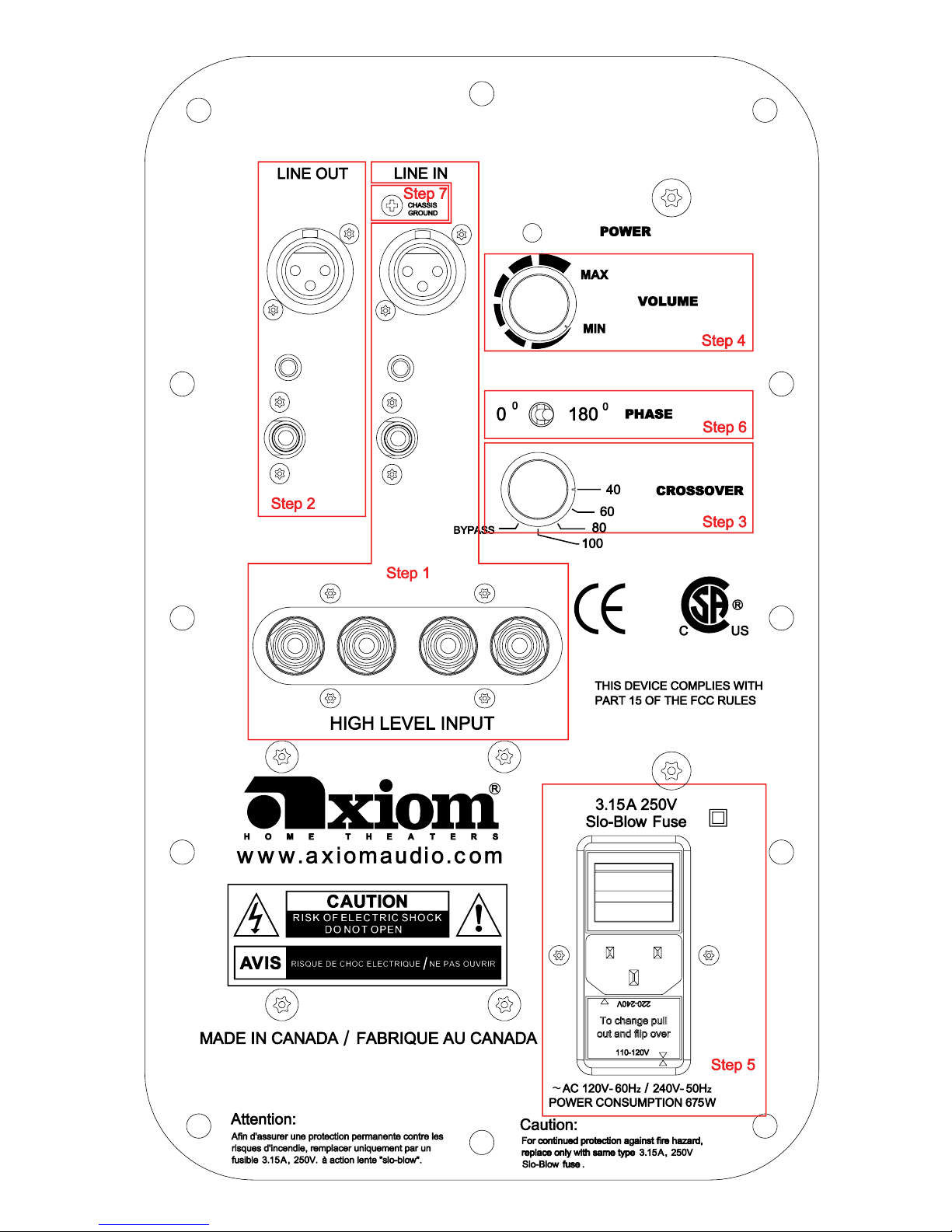
EP175 ELECTRICAL CONNECTIONS
Step 1:
LINE IN: the RCA line-level female input, second row, accepts a
standard RCA male plug. Connect a shielded coaxial cable, with
male RCA plugs on each end, from the A/V receiver or A/V preamp
processor’s Subwoofer Output jack to the RCA LINE IN female jack
on the EP175.
3.5mm MINI-Jack: this is for any 3Volt to 30Volt power on trigger.
It is also intended for trigger-controlled operation with future Axiom
products.
BALANCED XLR LINE IN: if the A/V receiver or A/V preamp-
processor has balanced XLR subwoofer line-out connections, you
may connect a Balanced XLR male connector to the XLR female
input. Otherwise, ignore this connector. Do not use a combination
of RCA and XLR input or output connectors.
HIGH LEVEL INPUT: Use these “speaker-level” or high-level 5-way
binding post connectors only if your receiver or preamp lacks a
dedicated line-level subwoofer output jack. Connect speaker cables
from your amplifier’s left-channel and right-channel speaker output
binding posts to the high-level inputs using banana plugs (single or
dual), spade connectors, pins, or bare cable if you wish (unscrew
the top of each binding post and insert the cable into the hole in the
post; tighten the knurled knob against the cable). Run a second pair
of speaker cables from these jacks to your main left and right front
speakers. Do not use these connectors if you are already using an
RCA or XLR line-level connection from the receiver or preamp to the
subwoofer. NOTE: BE SURE TO CONNECT BLACK TO BLACK
AND RED TO RED.
Step 2:
LINE OUT (RCA, Trigger and XLR Balanced):
An RCA line-level (female) output and balanced XLR output (male)
are provided for connection to a second subwoofer. Use a standard
shielded coaxial cable for connection of the RCA Line Out to the
second subwoofer. If you are using balanced XLR connectors, then
use the balanced Line Out for operation of a second EP175.
Step 3:
CROSSOVER: if you are using the Bass Management crossover
menu settings in your A/V receiver or processor, turn this control
to “BYPASS” to eliminate the EP175 internal crossover from the
circuit.
If you are using the HIGH LEVEL (Speaker Level) binding-post
inputs, set the crossover switch to 80 Hz for initial setup. If you
have floor-standing speakers (M40, M50, or M60), try a 60 Hz
crossover frequency, for the M80 try 40 Hz. If your main speakers
are bookshelf models M3 or M22, try the 80 Hz setting, for the M2
try 100 Hz. Ultimately you want to use a crossover frequency that
produces the smoothest blend of sound between the subwoofer and
your main speakers.
Step 4:
VOLUME: Set this midway to the 9 o’clock position for initial setup.
You can use this to manually regulate the subwoofer volume at
any time and during your initial setup adjustments with the other
speakers in your stereo or home theater system.
Step 5:
ON/OFF AC POWER/VOLTAGE SETTING: Your subwoofer is
supplied with a pop-out voltage regulator set for use with 100 - 120
volts from the A/C line. It can be easily removed and turned over to
set your EP175 to 220 volts from the A/C line.
Once you have made appropriate connections from the A/V receiver
or preamp/processor to the EP175 and set the voltage regulator
to the proper voltage, find a nearby AC wall outlet and connect
the main power cord to the three-wire socket at the bottom of the
control panel. Move the power switch to the ON setting and the LED
POWER indicator should glow Green. Leave the switch at the ON
setting unless you go away for an extended period. Moving it to OFF
will shut down all power to the subwoofer.
Step 6:
0 & 180 PHASE: This synchronizes the in/out movement of the
subwoofer cone driver with the other speakers in your system. Once
you have chosen the best location for your subwoofer, try flipping
the phase switch between 0 and 180 to see if one or the other setting
produces deeper and smoother bass output in your room. Leave the
switch at the setting that results in the smoothest and deepest bass
at several listening locations in the room. If you hear no difference,
leave the switch at the 0 position. Quite often the phase switch
makes no difference, but it’s dependent on your room and subwoofer
location.
Step 7:
GROUND LOOP:
If your subwoofer is producing a 50 or 60 Hz hum; remove the
Chassis Ground Screw. If this does not solve the hum, call 1-
866-244-8796 or consult the full manual at www.axiomaudio.
com/epmanual.html
POWER INDICATOR: The LED Power indicator glows Green
when it’s on and Red indicating Standby Mode.
Please Note: The EP350 will shut down if heavily over drivenin
into distortion. To reset, turn power switch OFF then ON.
NEED HELP TROUBLESHOOTING?
Please feel free to contact us at 1-866-244-8796 or
www.axiomaudio.com/manual_index.html for more information.
Visit www.axiomaudio.com/manual_index.html for full owners manual


IMPORTANT SAFETY INSTRUCTIONS
CAUTION
THERE ARE NO USER-SERVICEABLE PARTS IN THIS SYSTEM. TO PROTECT AGAINST THE RISK OF ELECTRICAL
SHOCK, DO NOT USE THE SUBWOOFER NEAR BATHTUBS, SINKS, SWIMMING POOLS, SAUNAS, IN WET
BASEMENTS, NEAR OTHER WATER SOURCES, OR IN RAIN. DO NOT ATTEMPT TO REMOVE THE AMPLIFIER FROM
THE SUBWOOFER CABINET. IF SERVICE IS REQUIRED PLEASE REFER TO AN AUTHORIZED AXIOM SERVICE
DEPOT.
THE SUBWOOFER HAS A BUILT-IN AMPLIFIER AND MUST HAVE ADEQUATE VENTILATION FOR COOLING PURPOSES.
DO NOT PLACE NEAR HEAT OUTLETS SUCH AS FURNACE REGISTERS OR OTHER SOURCES OF HEAT.
The exclamation point within an equilateral triangle is intended to alert the user to the presence
of important operating and maintenance (servicing) instructions in the literature accompanying
the product.
The lightning ash with arrow head symbol, within an equilateral triangle, is intended to alert
the user of the presence of un-insulated “dangerous voltage” within the product’s enclosure that
may be of sufcient magnitude to constitute a risk of electric shock to persons.
SAFETY PROCEDURES
• Ensure that you connect your Subwoofer only to the type of power supply indicated on the
amplifier faceplate, and ensure that the power cord cannot be walked on or otherwise damaged.
• To prevent electric shock, match wide blade of plug to wide slot, fully insert.
• Ensure that objects or liquids are not allowed to penetrate the enclosure.
• Your AXIOM Subwoofers are finished in a durable vinyl and from time to time should be wiped
clean gently with a slightly damp cloth to remove any dust or stains.
For any additional information or service, contact:
AXIOM, 2885 HWY 60
DWIGHT ON CANADA
P01 1H0
Phone: 1-866-244-8796
PRECAUTIONS
1. Read instructions - All the safety and operating instructions should be read before the product is
operated.
2. Follow instructions - All operating and usage instructions should be followed.
3. Retain instructions - The safety and operating instructions should be retained for future reference.
4. Heed Warnings - All warnings on the product and in the operating instructions should be adhered to.
5. Attachments - Do not use attachments not recommended by the product manufacturer as they may create
hazards.
6. Water and Moisture - Do not use this product near water - for example, near a bathtub, wash bowl,
kitchen sink or laundry tub, in a wet basement, or near a swimming pool or the like.

7. Accessories - Do not place this product on an unstable cart, stand, tripod, bracket or table. The product may fall,
causing serious injury to a child or adult and serious damage to the product. Use only with a cart, stand, tripod,
bracket or table recommended by the manufacturer, or sold with the product. A product and cart combination should
be moved with care. Quick stops, excessive force and uneven surfaces may cause the product and cart
combination to overturn.
8. Heat/Ventilation - Slots and openings in the cabinet are provided for ventilation and to ensure reliable operation of
the product to protect it from overheating. These openings must not be blocked or covered. This product should not
be placed in a built-in installation such as a bookcase or rack unless proper ventilation is provided or the
manufacturer’s instructions have been adhered to. The product should be situated away from heat sources such as
radiators, heat registers, stoves or other products (including amplifiers) that produce heat.
9. Power Sources - This product should be operated only from the type of power source indicated on the marking
label. If you are not sure of the type of power supply to your home, consult your product dealer or local Power
Company.
10. Ground or Polarization - This product may be equipped with polarized alternating current line plug (a plug having
one blade wider than the other). This plug will fit into the power outlet only one way. This is a safety feature. If
you are unable to insert the plug fully into the outlet, try reversing the plug. If the plug should still fail to fit, contact
your electrician to replace your obsolete outlet. Do not defeat the safety purpose of the polarized plug.
11. Lightning - For added protection for this product during a lightning storm, or when it is left unattended or unused for
long periods of time, unplug it from the wall outlet. This will prevent damage to the product due to lightning and
power-line surges.
12. Power-cord Protection - Power supply cords should be routed so that they are not likely to be walked on or
pinched by items placed upon or against them, paying particular attention to cords at the plugs, convenience
receptacles and at the point where they exit from the product.
13. Overloading - Do not overload wall outlets, extension cords or integral convenience receptacles as this can result in
the risk of fire or electric shock.
14. Object and Liquid Entry - Never push objects of any kind into this product through openings as they may touch
dangerous voltage points or short-out parts that could result in fire or electric shock. Never spill liquid of any kind on
the product. Cleaning - unplug this product from the wall before cleaning. Do not use liquid cleaners or aerosol
cleaners. Use a damp cloth for cleaning.
15. Servicing - Do not attempt to service this product yourself as opening or removing covers may expose you to
dangerous voltages or other hazards. Refer all servicing to qualified service personnel.
16. Damage Requiring Service - Unplug this product from the wall outlet and refer service to qualified service
personnel under the following conditions:
a) If the power supply cord or plug is damaged.
b) If liquid has been spilled, or objects have fallen into the product.
c) If the product has been exposed to rain or water.
d) If the product does not operate normally by following the operating instructions. Adjust only those controls that
are covered by the operating instructions as an improper adjustment of other controls may result in damage
and will often require extensive work by a qualified technician to restore the product to it’s normal operation.
e) If the product has been dropped or damaged in any other way.
f) If the product exhibits a distinct change in performance despite verifying that all system connections are
correct.
17. Replacement Parts - If replacement parts are required, be sure the service technician has used replacement parts
specified by AXIOM. Unauthorized substitutions may result in fire, electric shock or other hazards.
18. Safety Check - Upon completion of any service or repairs to this product, ask the service technician to perform
safety checks to determine that the product is in proper operating condition.
PRECAUTIONS

®
Axiom Audio Head Office 2885 Highway 60
Siège social Axiom Audio Dwight, ON Canada
P0A 1H0
Toll Free (North America) 1-866-244-8796
Sans frais (Amérique du Nord) 1-888-249-9143
Worldwide • International 1-705-635-3090
www.axiomaudio.com
Table of contents
Other Axiom Audio Subwoofer manuals

Axiom Audio
Axiom Audio SW36XFA User manual

Axiom Audio
Axiom Audio EP400 Epicenter User manual

Axiom Audio
Axiom Audio EP500 v3 User manual

Axiom Audio
Axiom Audio EP125 User manual

Axiom Audio
Axiom Audio EP125 User manual

Axiom Audio
Axiom Audio EP400 User manual

Axiom Audio
Axiom Audio EP600 User manual

Axiom Audio
Axiom Audio EP600 User manual

Axiom Audio
Axiom Audio EP600 Specification sheet

Axiom Audio
Axiom Audio Epicenter EP350 User manual