7
PRESET VOLUME LEVELS
It is possible to preset the volume when unit is powered up. Press the SEL button until unit is in
DSP mode. To select the volume to remain at the same levels at switch off, press “SEL” until
VOL LAST is displayed. The volume will resume at the level it was when the unit was turned
off. To set the volume to a predetermined level at switch on, press SEL again so that VOL ADJ is
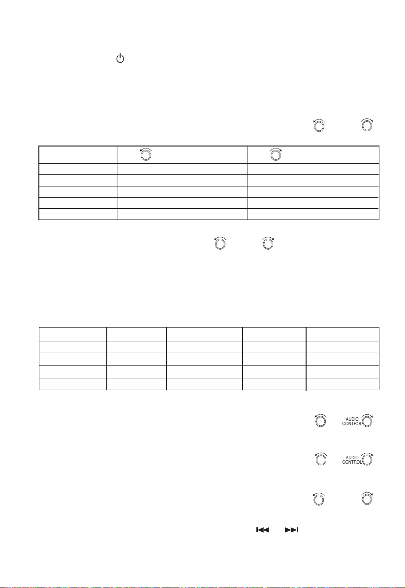
displayed. Then rotate
AUDIO
CONTROL AUDIO
CONTROL
or
AUDIO
CONTROL AUDIO
CONTROL
to select the desired volume levels.
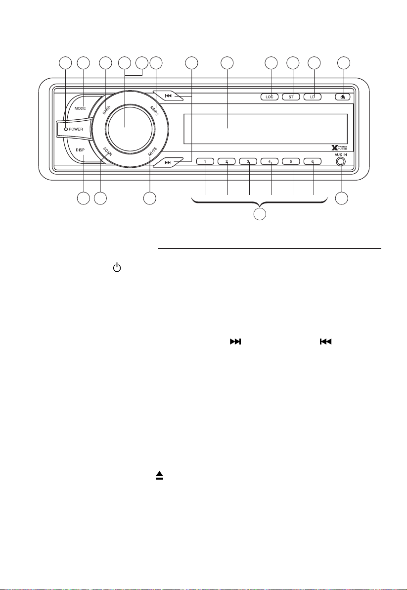
4. LOUDNESS BUTTON (LD)
Press this button for bass and treble boost. Push button again to return to normal operation. This
function is useful when listening at low levels. Loudspeakers are inefcient at low power levels
and will tend to sound at. The loudness control will boost the bass and treble response for a more
lively performance. While this function is operating, the display shows “LOUD”
5. LCD DISPLAY
The Liquid Crystal Display will show the current settings of the unit.
6. BAND SELECTOR (BAND)
Press this button to toggle through the preset Radio FM1---FM2---FM3---AM1---AM2.
7. AUTOMATIC OR MANUAL TUNING (FREQ UP OR FREQ DOWN )
When pressed for less than 1 second, the unit operates in manual tuning mode.
When pressed longer than 1 second, the unit operates in automatic tuning mode.
If the keys are not pressed again within 3 seconds, the unit will return to SEEK mode.
8. LOCAL/DISTANT BUTTON (LOC)
Press Local/Distant (LOC) button for listening to weak stations. “LOC” indicator will appear on
the display. Press this button again (Distant mode) for normal operation.
9. DISPLAY BUTTON (Set the Clock)
Selects radio frequency or clock display.
To set the clock:
1. With clock display selected, hold down (DISP) button until clock display starts ashing.
2. Rotate
AUDIO
CONTROL AUDIO
CONTROL
to change minutes,
AUDIO
CONTROL AUDIO
CONTROL
to change hours.
3. Press (DISP) button to start clock.
10. PRESET STATIONS
Six numbered preset button store and recall stations for each band.
Storing a station:
1. Select a band (if needed)
2. Select a station
3. Hold a preset button longer than one second. Preset number appears in the display when station
is saved.
Recall a station:
1. Select band (if needed)
2. Press a preset button for less than one second to select stored station.
11. ‘SCAN’ AUTOMATIC TUNING CONTROL (SCAN)
This operation is similar to normal search. It holds the station for only 5 seconds before moving to
the next station. To store the desired station into preset memory (see point 10)