AXITEC AXIhycon 5H User manual

AXIhycon-EN231024
AXITEC Energy GmbH & Co. KG, Otto-Lilienthal-Str. 5, 71034 Böblingen, Germany, www.axitecsolar.com
Quick Start Guide
AXIhycon
5 –10 H

1
AXIhycon-EN231024
1. PREPARATION FOR STARTUP
- Ensure accessibility to all devices.
- Check the installation and ventilation of the inverter.
- Ensure the top of the inverter is free of obstacles.
- Lay cables in a protected manner.
- Connect the Bluetooth antenna.
2. DOWNLOADING THE APP
1. Visit www.soliscloud.com and download the app.
2. Search for "SolisCloud" on the Google Play Store or App Store.
3. Scan the QR code to download "SolisCloud."
3. CONNECTORS
Connector
Function
BMS
Used for CAN communication between inverter and lithium battery BMS.
Meter
Is employed for RS485 communication between the inverter and the smart meter. This is necessary to
implement normal hybrid control logic.
RS485
(Optional) Utilized for Modbus RTU communication with external devices or third-party controls.
DRM
(Optional) In the context of implementing demand response or logic interface functions, this feature may
be required in the UK and Australia.
P-A/P-B
(Optional) Communication ports for parallel operation (reserved).
DO/DI
(Optional) Connection for potential-free contact (reserved).
- Connect the AC power supply.
- Connect additional communication ports (BMS, meter, RS485, DRM, P-A/P-B, DO/DI) as needed.
WARNING:
Please be aware that this is a quick guide. It is absolutely essential to carefully read and follow the
complete instructions to ensure proper setup.

2
AXIhycon-EN231024
NOTE:
The pin configuration of the meter port (at the inverter)
follows the EIA/TIA 568B standard.
RS485A on Pin 1: Orange/White
RS485B on Pin 2: Orange
RS485B
RS485A
NOTE:
The pin configuration of the Smart Meter for RS485 is as follows:
RS485A is connected to pin 14.
RS485B is connected to pin 13.
4. CONNECTING THE SMART METER
Install the smart meter for communication.
NOTE:
Please ensure that the alignment of the current trans-
former (CT clamps) is correct, as otherwise the system
will not function properly.
CAUTION:
Ensure that the AC cable is completely disconnected from the power source
before connecting the smart meter, EMS, and CT clamps.

3
AXIhycon-EN231024
NOTE:
The pin configuration of the RS485 port follows
the EIA/TIA 568B standard.
RS485A is connected to pin 5 with blue/white.
RS485B is connected to pin 4 with blue.
RS485A
RS485B
5. CONNECTING AN ENERGY MANAGEMENT SYSTEM (EMS) [OPTIONAL]
6. CONNECTION OF THE POWER STORAGE SYSTEM
Use the supplied CAN cable to connect one end to the CAN port of the battery and the other end to the BMS
port of the inverter.
7. CONNECTING THE DC CONNECTIONS
- Check the polarity of the photovoltaic (PV) and battery strings.
- Measure the AC voltage and frequency.
- Connect the photovoltaic and battery power cables to the inverter.
8. INSTALLATION OF THE INVERTER (OFFLINE)
CAUTION:
Ensure that the AC cable is completely disconnected from the power source
before connecting the smart meter, EMS, and CT clamps.
NOTE:
The pin configuration of the BMS and CAN ports ad-
heres to the EIA/TIA 568B standard.
CAN-H is on pin 4 (blue)
CAN-L is on pin 5 (blue/white).
CAN-L
CAN-H

4
AXIhycon-EN231024
- During the initial setup, you will be prompted to set a password. Please follow the on-screen instruc-
tions.
- If asked for control passwords:
osolis#100 End-user level
osolis#700 Installer level
9. INTERNET CONNECTION (OPTIONAL)
9.1 LAN-CONNECTION
Step 1: Turn on the external AC switch.
Step 2: Connect the data logger via the COM port.
Step 3: Connect the data logger to the router using an LAN cable.
- All LEDs on the data logger should be lit steadily.
CAUTION:
No other device should be connected to the inverter via USB except for the
data logger, as this may cause damage to the inverter.

5
AXIhycon-EN231024
NOTE:
Die Rote LED gibtan, dass der Datenlogger mit Stromversorgt wird, die gelbeLED
zeigt an, dass eine Verbindung zwischen Datenlogger und Wechselrichter besteht.
Die grüne LED gibt an, dass der Datenlogger eine Verbindung zur SolisCloud auf-
gebaut hat.
NOTE:
The red LED indicates that the data logger is powered,
the yellow LED signifies a connection between the data logger and the inverter,
the green LED indicates that the data logger has established a connection to Solis-
Cloud.
9.2 WIFI-CONNECTION
Step 1: Activate the external AC switch.
Step 2: Connect the data logger via the COM port (LEDs should illuminate).
Step 3: Ensure that your mobile phone/laptop does not automatically connect to the home Wi-Fi.
Step 4: Connect to the Wi-Fi of the data logger "D_...".
Step 5: Open the browser and enter the IP address: "10.10.100.254".
▪Username: "admin", Password: "123456789".
Step 6: Click on "Quick Set," select the home network, enter the home network password, and click
on Save.
- All LEDs on the data logger should remain lit continuously.
9.3 CREATING PLANT AND ADDING DATA LOGGER
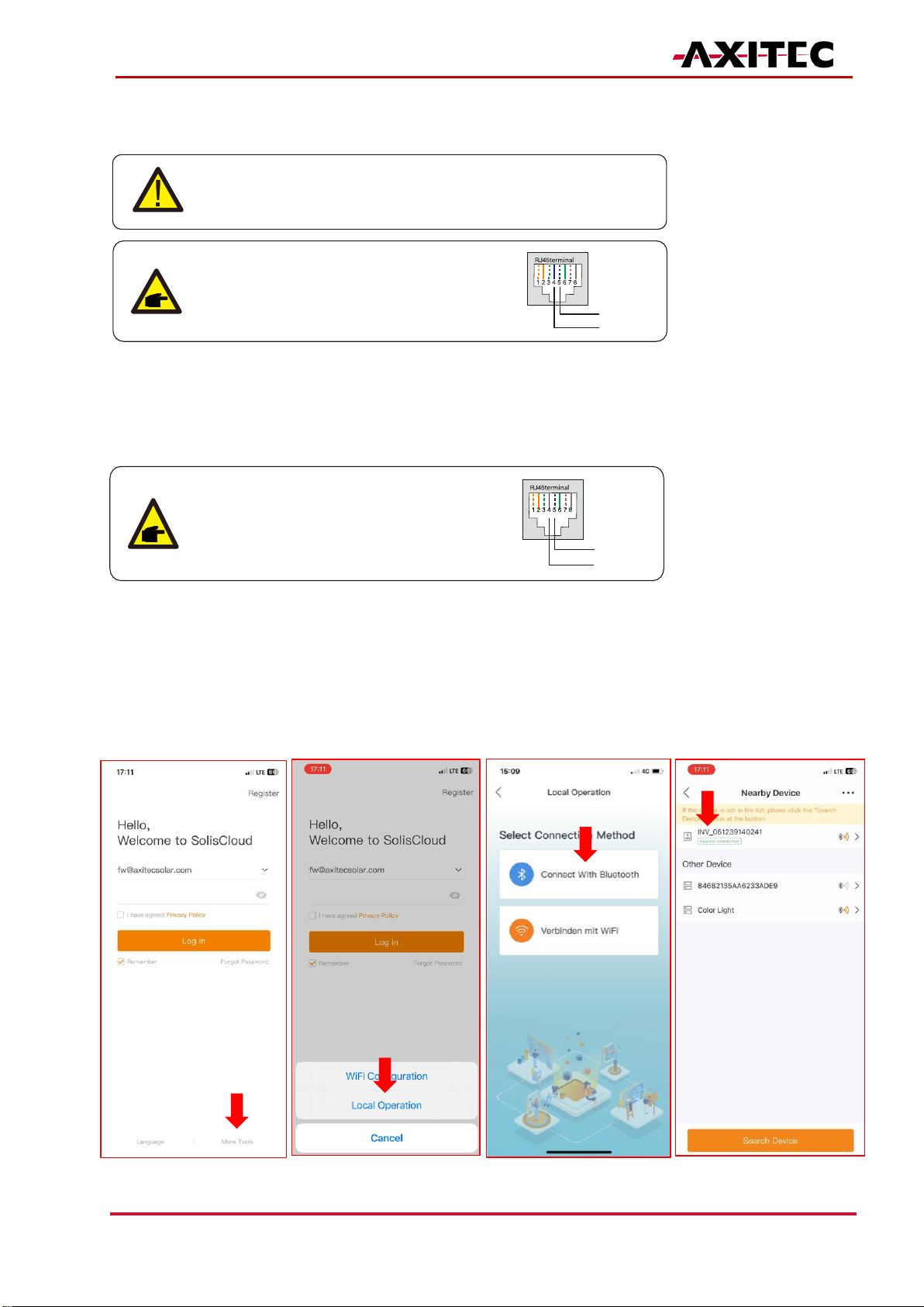
- Log in to the SolisCloud app.
- Fill in all necessary fields.
- Enter the owner's email address to allow them to monitor their plant.
CAUTION:
Es darf kein anderes Gerät außer dem Datenlogger über USB mit dem Wech-
selrichter verbunden, da sonst Schäden am Wechselrichter entstehen kön-
nen.

6
AXIhycon-EN231024
- Add the logger.
- The inverter will appear automatically after a short period.
10. CHANGE PASSWORD
The installer has the ability to reset the password.

7
AXIhycon-EN231024
11. TURNING ON THE SYSTEM
Step 1: Turn on the AC breaker at the power connection point.
Step 2: Turn on the DC switch of the inverter.
Step 3: Turn on the battery switch.
12. TURNING OFF THE SYSTEM
Step 1: Turn off the AC breaker at the power connection point.
Step 2: Turn off the battery switch.
Step 3: Turn off the DC switch of the inverter.
Step 4: Wait until the device is powered off, and the system shutdown is complete.
In case of discrepancies in this user manual, please refer to the actual products.
If you encounter any issues with the inverter, please identify the inverter's serial number (S/N) and contact us.
We will strive to respond to your inquiry as quickly as possible.
AXITEC Energy GmbH & Co. KG
Otto-Lilienthal-Straße 5
D-73014 Böblingen
Mail: energy@axitecsolar.com
Tel.: +49 (0) 7031 6288-5170
This manual suits for next models
1
Table of contents
Other AXITEC Inverter manuals
Popular Inverter manuals by other brands

TESTO
TESTO REXS user manual

Tripp Lite
Tripp Lite PV1000FC Features & specifications

APsystems
APsystems QS1 Quick installation guide

Winco
Winco WL22000VE/A Installation and operator's manual

Black & Decker
Black & Decker PI750LA instruction manual

Kutai electronics
Kutai electronics EA05A-B Operation manual