TESTO REXS User manual

testo REXS
User Manual

Content
2
Content
1Declaration of Warranty ............................................................................................... 4
1.1. Type of Designation ....................................................................................................................... 4
1.2. Manufacturer ................................................................................................................................4
1.3. Warranty .......................................................................................................................................4
2Precautions ................................................................................................................... 5
2.1. Foreword.......................................................................................................................................5
2.2. Liabilities .......................................................................................................................................5
2.3. Copyright ©.................................................................................................................................... 5
3Safety ............................................................................................................................ 6
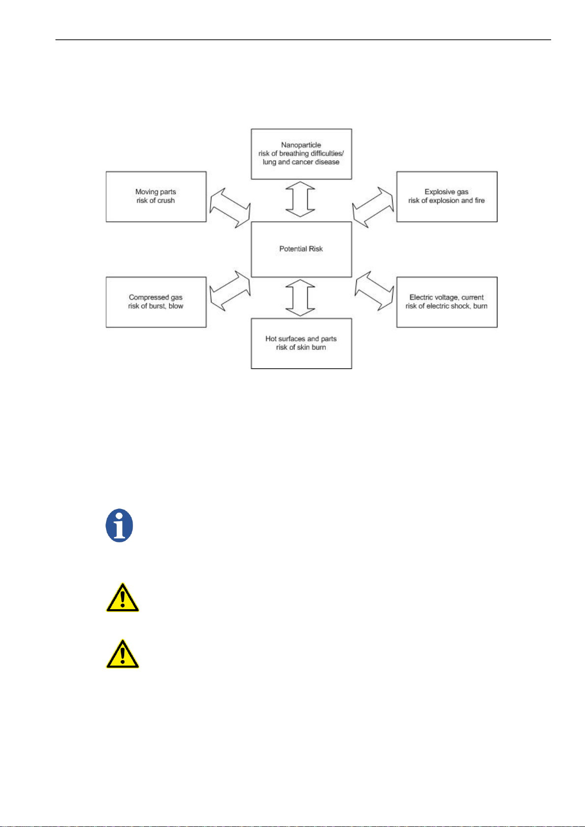
3.1. Risk Types......................................................................................................................................6
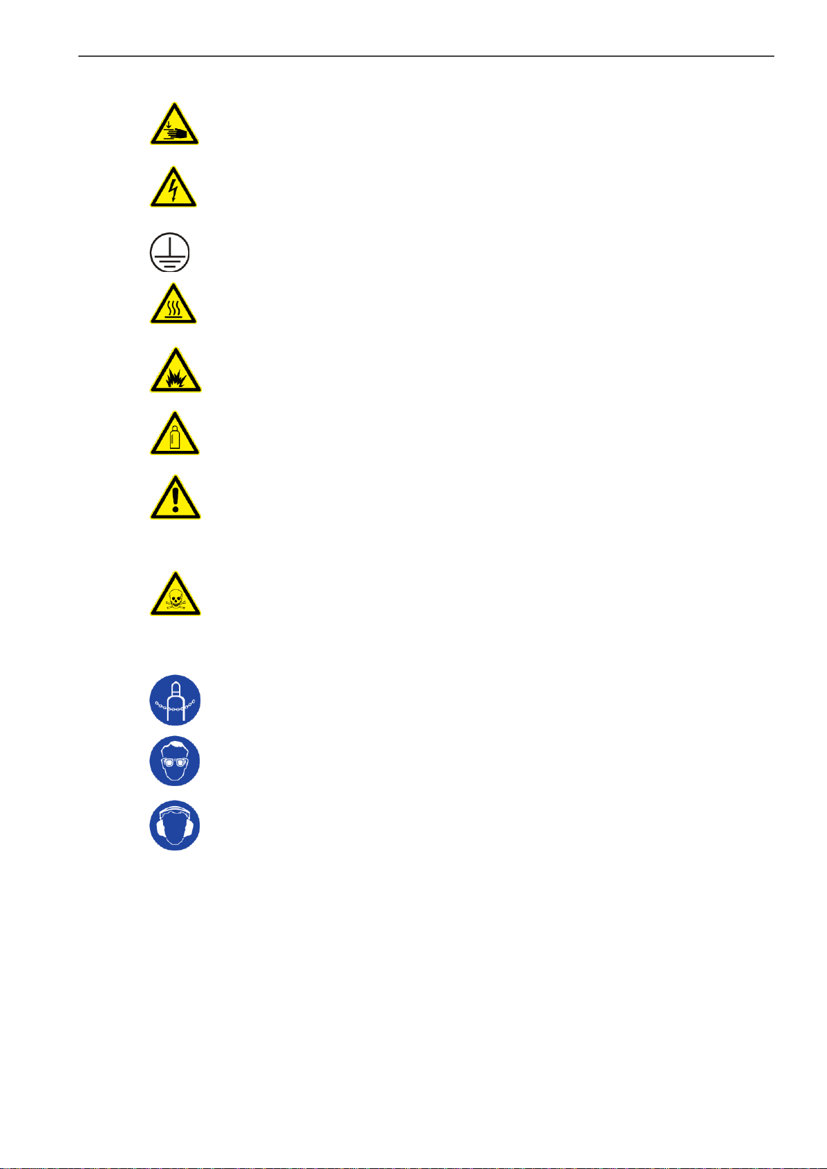
3.2. Labels and Explanations.................................................................................................................6
4System Overview........................................................................................................... 8
4.1. Soot Generation Principle of testo REXS .........................................................................................8
4.1.1. Principle...............................................................................................................................8
4.1.2. Applications .........................................................................................................................8
4.1.3. Functionality ........................................................................................................................ 9
4.2. The Benefits Are ............................................................................................................................ 9
4.3. Function Principle .......................................................................................................................... 9
4.4. The System....................................................................................................................................9
4.4.1. Soot Generator .................................................................................................................. 10
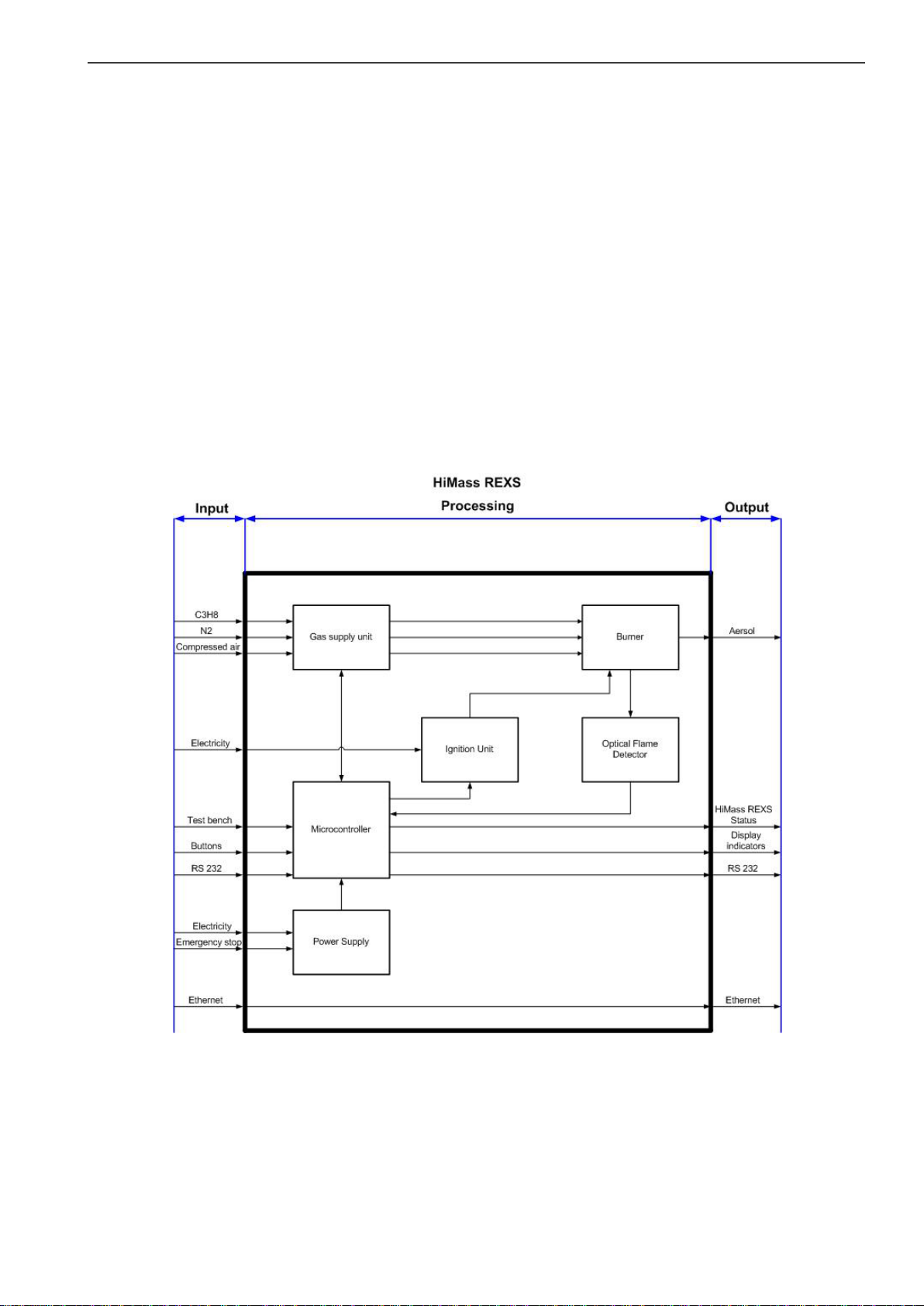
4.4.2. Input.................................................................................................................................. 10
4.4.3. Processing.......................................................................................................................... 10
4.4.4. Output ............................................................................................................................... 11
4.5. Front Panel Operational Elements................................................................................................ 12
4.6. Back Panel Operational Elements................................................................................................. 14
4.7. Back Panel Connectors................................................................................................................. 15
5Transportation, Unpacking and Extend of Delivery..................................................... 15
5.1. Transportation............................................................................................................................. 15
5.2. Unpacking.................................................................................................................................... 16
5.3. Storage, Acclimatisarion............................................................................................................... 17
5.4. Extent of Delivery ........................................................................................................................ 18
6Setting up and installation .......................................................................................... 20
6.1. Operation Environment Requirements......................................................................................... 20
6.2. Installation................................................................................................................................... 21
6.3. Test Stand Preparation................................................................................................................. 24
6.4. Operating Instructions ................................................................................................................. 24
6.5. Note ............................................................................................................................................ 25

Content
3
6.6. Warning....................................................................................................................................... 25
6.7. Test Bench Setup Examples.......................................................................................................... 25
7testo REXS Testing/Programming GUI......................................................................... 28
7.1. System Requirements .................................................................................................................. 28
7.2. Installation Procedure.................................................................................................................. 28
7.3. Uninstallation Procedure ............................................................................................................. 29
7.4. Serial Connection to testo REXS ................................................................................................... 29
7.5. Controls and Indicators................................................................................................................ 29
7.6. Operation of the testo REXS GUI .................................................................................................. 31
7.7. Errors/Troubleshooting................................................................................................................ 33
7.7.1. Communication Errors ....................................................................................................... 33
7.7.2. Testo REXS Errors............................................................................................................... 33
8Appendix ..................................................................................................................... 36
8.1. Specification, Technical Data........................................................................................................ 36
8.2. Service Guide............................................................................................................................... 37
8.2.1. Cleaning of the Burner Outlet............................................................................................. 37
8.2.2. Cleaning of the Spark Ignition Electrode ............................................................................. 38
8.2.3. Exchange of the HEPA Gas Filter Cartridges ........................................................................ 38
8.2.4. Exchange of the Spark Ignition Electrode ............................................................................ 38
8.2.5. Cleaning of the Optical Flame Detection Unit...................................................................... 38
8.3. Definitions, Units and Conversion Table ....................................................................................... 39

1 Declaration of Warranty
4
1Declaration of Warranty
Manual Version History:
Version: V4.0
Date: November 2016
1.1. Type of Designation
This user manual refers to the instrument type and version as listed below. It replaces all
previously dated user manuals for this instrument.
Type: testo REXS
1.2. Manufacturer
Testo SE & Co. KGaA Tel: +49 7653 681 5062
Testo-Strasse 1 Fax: +49 7653 681 95062
79853 Lenzkirch web: www.testo-particle.com
Germany email:sales-nanoparticle@testo.de
For technical support contact your local service contractor or Testo techsupport.
email: support-nanoparticle@testo.de
1.3. Warranty
Testo SE & Co. KGaA warrants that this product adheres to the specified properties for a period
of twelve (12) months from the date of delivery.
Excluded from the warranty are all parts subjected to normal wear as any fuses, batteries or
other consumable parts. Also excluded are: Defects resulting from abnormal use, in particular
outside the intended purpose; lack of maintenance; improper use or malicious damage. Warranty
is void if actions are carried out which are not described in the documentation nor authorized by
Testo SE & Co. KGaA.
Testo SE & Co. KGaA does not provide any warranty on finished goods manufactured by others.
Only the original manufacturer's warranty applies.
There are no user-serviceable parts inside testo MD19-3E and some very sensitive parts. Do not
open your testo MD19-3E, as you may damage it. Warranty is voided if the case is opened and
warranty-seal is broken.
Parts repaired or replaced as a result of repair services are warranted to be free from defects in
workmanship and material, under normal use, for 90 days from the date of shipment.

2 Precautions
5
2Precautions
2.1. Foreword
This manual guides you through the installation, starting up, operation and maintenance
procedures of the testo REXS. In detail you will find information about the system as
safety
functionality of the testo REXS, technical information and specifications
installation of the testo REXS and accessories
handling, operation, maintenance and troubleshooting
The instrument is not intended to be operated alone but integrated into a test
stand for filters or particle filter in industrial production and development.
Therefore the documentation and manual is not addressed to the end user but
rather to the test stand manufacturer. The test stand manufacturer has to
generate a self contained user manual.
Follow the instructions provided by this manual for safe and proper operation of the testo REXS
soot aerosol generator.
Before installing and operating the testo REXS, the operator or service
technician has to read and follow carefully this manual. For improper function,
damages or injuries caused by ignoring the instructions by this manual no
liabilities are accepted.
2.2. Liabilities
Testo SE & Co. KGaA accepts no liability to improper function or injury caused by
neglecting the instructions provided by this manual or instructed person
improper installation, operation, application, or maintenance
operation by untrained staff
any technical modification not carried out by Testo SE & Co. KGaA or an authorized
service partner
use of not genuine spare parts
The content of this manual is generated with most accurateness. Testo SE & Co. KGaA does not
guarantee completeness, correctness and being up to date. Testo SE & Co. KGaA reserves the
right to revise the content of the manual at any time and without notice.
Follow the guidelines below to ensure proper operation of the instrument:
read this instruction manual before installation and operation
always use gas of specified quality and purity (propane and nitrogen) when operating this
aerosol generator
make sure that the compressed air supply pressure and gas never exceeds 8 bar
make sure that the maximum pressure at the compressed air inlet is always less than 8
bar, for propane and nitrogen less than 5 bar
do not restrict the aerosol outlet. The aerosol generator can only work against pressure up
to 500 mbar above atmospheric pressure
always use genuine replacement parts supplied by Testo SE & Co. KGaA
allow the instrument to cool off before performing any maintenance at the instrument
2.3. Copyright ©
All work and contents done or generated by Testo SE & Co. KGaA are subject of the German
copyright © and law for intellectual property. This copyright includes all specification data of the
instrument or part of it, electrical and fluidic and mechanical schematics, pictures, diagrams and
text. Copying, editing, publishing or any other utilisation requires a written agreement of SE & Co.
KGaA.

3 Safety
6
3Safety
3.1. Risk Types
The following diagram shows typical risks that could cause damage or injury while handling the
testo REXS.
Fig. 3.1: Risk types
3.2. Labels and Explanations
When operating testo REXS, you are always operating under certain risk factors as electricity,
explosive and compressed gases, hot surfaces, moving parts and nanoparticles. Therefore testo
REXS includes several safety features. Nevertheless, some precautions still need to be taken to
ensure safe and reliable operation. Listed labels, Cautions, and Warnings are explained in
general, and the further specific labels refer to type of hazard and danger.
Note
Note
Note means this content describes important, useful and/or necessary
information to help guide you through the manual.
Caution and Warning
Caution
Caution means be careful. If you do not follow the manual instruction you might
cause an instrument or accessories damage, but no human injury. Also Caution
refers to important information about installation, operation and maintenance.
Warning
Warning means that improper operation could cause a serious human or
instrument damage or injury with consequence of irrevocable instrument
damage.

3 Safety
7
Warnings for testo REXS
Crush
Crush hazard. Keep hands clear of moving parts. Lockout/tagout before
servicing.
Electric Shock
Hazardous voltage. Contact may cause electric shock or burn.
Turn off and lock out system power before servicing.
Protection earth
The electroconductive terminal is connected to protection earth.
Skin Burn
Hot surface. Do not touch. To avoid possible skin burns, wear heat protection
gloves or turn heating off and allow surfaces to cool down before servicing.
Explosion
Explosion hazard. Inflammable gas. A gas leak may cause an explosion or burn.
Before turning on the instrument check gas leak tightness.
Gas filled cylinders
Compressed and explosive gas. Broken or leak cylinder may destroy the locality
and environment.
Soot Nanoparticles
Soot particles hazard. When breathed in, soot particles may cause adverse
carcinogenic health effects to organism. The human immune system is not able
to completely deflate inhaled nanoparticles; they may enter and remain in the
human body.
Toxic gas
Toxic gas hazard. The emission consists of toxic gas CO and CO2, that may
result in adverse health effects.
Safety dispositions
Gas cylinder support
Risk of tilting gas cylinder. Secure the standing gas cylinder with a chain or belt.
Eye protection
Eye hazard. Explosive gas surrounding, particles and bright flame may affect the
eyesight.
Ear protection
Ear protection. To fade out monotone sound location.

4 System Overview
8
4System Overview
Fig. 4.1: testo REXS instrument
4.1. Soot Generation Principle of testo REXS
4.1.1. Principle
The soot aerosol generator is simulating the exhaust from a diesel combustion engine. The gas
fuel burner generates soot of selectable particle size and number concentration. The function
principle is based on a propane fuel diffusion flame that is quenched by air. From this follows that
propane (C3H8), nitrogen (N2) and air are transformed into carbon monoxide (CO), carbon dioxide
(CO2), water vapour, and soot nanoparticles.
4.1.2. Applications
Compared to a diesel combustion engine, testo REXS generates reproducible, constant and
stable exhaust gas flow and especially soot nanoparticles. This is a gain for the filter industries
regarding measurement of any particle filters of combustion engines as vehicles, ships,
locomotives, or cranes and calibration of engine test benches. Testo REXS may also be used to
test and certify air intake filters, cabin filters or dust absorbers.

4 System Overview
9
4.1.3. Functionality
Testo REXS is built up in a mobile 19'' rack. The straightforward design and clear layout ease its
operation. Indicators, display and software enable control and monitoring of the control
parameters.
4.2. The Benefits Are
Soot aerosol generator, simulating exhaust from a modern diesel combustion engine.
Real soot nanoparticles, reproducible in size and concentration.
Aerosol output flow approx. 700 lN/min.
Adjustable particle sizes of approx. 60, 80 and 100 nm.
Soot nanoparticles mass output of 1.5 g/h at 80 nm.
Capable to work against back pressure up to 500 mbar.
Flexible and simple operation.
Simple test bench integration.
Local and/or remote control.
Very low maintenance effort needed, low down-time.
4.3. Function Principle
Fig. 4.2: Function principle
4.4. The System
To operate testo REXS, only propane, nitrogen, compressed air, and one phase electricity is
required.
Gas and air supply, power supply and test bench devices mounted to the burner outlet have to be
provided and installed by test bench manufacturer. The block diagram in Fig. 4.2 shows the testo
REXS system design with all electrical and gas lines, by inputs and outputs.

4 System Overview
10
4.4.1. Soot Generator
testo REXS is controlled by a microcontroller. It supervises gas pressures, gas flows, remote
control signal, flame status and aerosol temperature, and it drives automatic ignition, display and
LED indicators. Furthermore it controls the operating point change, start-up, gas mass flow
controller, valves and shut down. With only the two buttons Burner ON/OFF and Operating Point
at the front panel testo REXS is controlled. Communication to the remote operation software is
done by a protocol over a EIA-232 serial interface.
4.4.2. Input
Gas supply unit, propane and nitrogen
Compressed propane and nitrogen supply with the matching technical requirements are
connected to testo REXS by encoded quick couplings. Precision pressure regulators adjust the
gas pressures, before the gases are purified through HEPA filters. Pressure switches and safety
shut-off valves control the minimal required pressure for safe operation. Mass flow controllers set
the nominal gas flows depending on the selected operating point. Propane and nitrogen are
mixed downstream of the MFC and lead into the burner.
Compressed air
Oxidation air:
The compressed oxidation air is supplied through an encoded quick coupling. It is purified
through a prefilter and a HEPA filter. Oxidation air pressure is controlled by a precision pressure
regulator. Pressure switch and safety shut valve controls the minimal required operation
pressure. A mass flow controller sets the nominal oxidation air flow depending on the selected
operating point. Oxidation air is then lead to the bottom part of the burner.
Note
Oxidation air is feeded internally from quench air in standard setup. A separate
oxidation air supply may be used if necessary.
Quench air:
The quench air is supplied through an encoded quick coupling. It is prefiltered and the pressure is
controlled by a precision pressure regulator. A HEPA filter purifies the quench air before it flows
into the MFC. Quench air is controlled depending on the selected operating point. The quench air
is lead to the mid part of the burner.
Operation elements:
Burner ON/OFF starts and stops production procedure.
Operation button switches over into the different aerosol production point.
Emergency stop immediately shuts down the process.
Communication interfaces:
RS232 is the communication interface between Microcontroller and external Notebook or PC
Desktop. Ethernet connects the internal interface from the notebook to the user ethernet.
4.4.3. Processing
Ignition unit
The flame is ignited with a high voltage spark ignition unit. The ignition energy is provided by high
voltage transformer with a capacity of 15 kV. During the ignition procedure a carriage moves the
spark ignition electrode into the combustion chamber and ignites the injected combustion gas. As
soon as the optical flame sensor detects the flame the electrode carriage is refracted to its initial
position, as well as after 5 unsuccessful spark ignition sequences.
Optical flame detector
The optical flame sensor detects the flame, observing the combustion chamber from the bottom
and reports the flame status to the microcontroller.
Power supply unit
The power supply unit provides 24 VDC power to the several subsystems of testo REXS. Input
voltage may be in a range of 90 to 250 VAC (wide-range input). Fuses values may change
depending on the actual supply voltage.

4 System Overview
11
4.4.4. Output
Display signal
It monitors current status of all controlled parameters.
Burner
The mass flow controlled mixture of propane and nitrogen is fed into the center of the combustion
chamber. The oxidation air is surrounding the fuel gas. The fuel gas and the oxidation air are not
mixed; a combustible mixture is only formed at the contact surface of the two gases. The flame
size changes with fuel, gas flow and mixture ratio.
A high volume quenches the upper part of the flame. The hot aerosol (gas with particles), which
consists of air, carbon dioxide (CO2), carbon monoxide (CO), water vapour and soot particles,
leaves the combustion chamber at the top of the burner.
The soot nanoparticle forming process; Laminar diffusion flame
Since the flame only burns at its outer surface, the gas inside the flame is heated up until the
propane is cracked into hydrogen (H2) and carbon (C). The carbon core particles ascend inside
the flame and grow. At the point where the quench air hits the flame, the flame is extinguished
and the soot nanoparticles are conserved in the actual size and number particles remain inside.
The longer the flame, the more the particles grow in size due to coagulation effects (soot particles
collide and stick together).
Fig. 4.3: Soot nanoparticle processing
Aerosol particles
Propane
Air

4 System Overview
12
4.5. Front Panel Operational Elements
The operating front panel at the left side includes two buttons, a display and seven LED
indicators.
Pos #
Description
Function
1
Burner ON/OFF
Start/Stop / confirm messages / clear errors
2
Operating point
Chosse operating point / cancel/quit
3
Four dot matrix display
Status / error codes / messages
4
LED indicator
Refer to table below for a detailed function description
Fig. 4.4: Front panel
LED signal lamps
Active green indicators refer to a positive status and therefore to a reliable operation. Red
indicators refer to an error.
Description
green
red
dark
Flame
Flame on
Flame not detected
Burner off
Run/ Standby
Run mode
Standby mode
Burner off
Fuel Gas 1)
Propane ready, flow
Propane not ready, out of
tolerance
Burner off
Fuel Dilution 1)
Nitrogen ready, flow
Nitrogen not ready, out of
tolerance
Burner off
Oxidation Air 1)
Oxidation ready, flow
Oxidation not ready, out
of tolerance
Burner off
Quench Air 1)
Quench air ready, flow
Quench air not ready, out
of tolerance
Burner off
Back pressure
Back pressure below
500 mbar
Back pressure above
500 mbar
Burner off
Note
The range of tolerance is
1) within ±3 % of the end range value
1) over ± 3% and between ±6 % of the end range value
1
3
4
4
2

4 System Overview
13
The operating front panel at the right side includes a propane concentration warning indicator and
an emergency stop button.
Pos #
Description
1
Fuel Gas Alarm
In combination with an audio warning the fuel gas
alarm indicator lights up when a high propane
concentration is detected. Clear by pushing the
button when the problem is resolved.
2
Emergency Stop
Interrupt power supply and immediately stop testo
REXS operation. Put back by pushing and also
turning right side the button when the problem is
resolved.
Fig. 4.5: Warning indicators
Warning
Explosive gas. Propane sensitive safety devices. In case of any malfunction shut
down all other electrical devices in the same room. Room and device must be
evacuated!
Flame detector
Active green indicators refer to a positive status and therefore to a reliable operation. Red
indicators refer to an error.
Pos #
Description
Connector
1
Flame detector unit
56 x 56 x 46mm
customized flame detector
2
Communication port
4 pin 14 mm socket
3
LED indicator,
Flame status
Green: ON
Red: OFF
Fig. 4.6: Flame detector
1
2
2
1
3

4 System Overview
14
4.6. Back Panel Operational Elements
Gas supply connectors
Pos #
Description
Connector
1
Propane C3H8
Swagelok quick coupling,
code orange
2
Nitrogen N2
Swagelok quick coupling,
code black
3
Oxidation air
Legris quick coupling, ISO
B6 1)
Fig. 4.7: Gas supply connector
Electrical power and compressed air connectors
Pos #
Description
Connector
1
Mains power plug
IEC 60320-C14, plug type
2
Main switch
0: off
1: on
3
Compressed air
Legris quick coupling, ISO
B8
Fig. 4.8: Electrical and air connectors
Internal fuses
Pos #
Description
Connector
1
F201, Fuse Spark Ignition
Weidmüller
2
F202, Fuse Notebook drawer
Weidmüller
Fig. 4.9: Internal fuses
1
2
3
1) Note: oxidation air is supplied internally in standard setup
1
2
3
1
2

5 Transportation, Unpacking and Extend of Delivery
15
4.7. Back Panel Connectors
Pos #
Function
Connector
1
Electrical power supply for
control insert. Power is
supplied from main power
in standard setup.
Type IEC 60320-
C14 plug
2
Control insert supply
switch
0: control insert off
1: control insert on
3
Control insert fuse
Main voltage fuse,
5x20mm 1)
4
Spare insert fuse
Main voltage fuse,
5x20mm 1)
5
Closing contact on 1-2,
sets testo REXS from
standby mode to run mode
2)
Feeback:
3-4 closed: stby
3-5 closed: run
5 pin 18 mm socket
6
Opening contact on 1-3,
interrupts power supply 3)
3 pin 18 mm socket
7
EIA-232 serial
communication with PC
9 pin Sub D socket
8
Internal diagnostic, for
factory only use
25 pin Sub D socket
Fig. 4.10: Back panel connectors
5Transportation, Unpacking and Extend of Delivery
5.1. Transportation
Caution:
The wooden transportation box is particularly designed for safe transportation of
testo REXS. Store the transportation box in a dry place when not used. Use only
the original packaging for transportation or shipping of testo REXS. The
instrument may suffer serious damage if it is not shipped in the original
transportation box.
1
5
3
2
4
6
8
7
1) note: refer to the label next to the fuse carrier for replacement fuse type and capacity.
2) note: a plug with 1-2 bridge is supplied with testo REXS
3) note: a plug with 1-3 bridge is supplied with testo REXS

5 Transportation, Unpacking and Extend of Delivery
16
Note:
testo REXS is shipped in a reusable, wooden transportation box. This box can
be transported either in upright or in lying position. Use a pallet lifting truck or a
pallet jack.
Warning:
When moving the box in an upright position, take precautions to ensure that it
does not tip.
Note:
ISPM15 Packing Regulation.
The wooden packaging is subject to the ISPM15 regulation, that defines how to
cover chemically wooden packagings for international transportation. The
ISPM15 label and the packaging manufacturer identification code is printed at
the front cover of the package.
5.2. Unpacking
Once the box is in the right place, put it in upright position. Loosen the 6 clamps and remove the
front cover. Take out the wooden ramp that is stored in the ceiling of the box and attach it to the
countersinks at the box floor. Make sure that the ramp is held in the positioning holes. Remove
the fastening belts and the frontside clamp board. Roll testo REXS out of the box carefully.
Note:
Follow the instruction sheet „how to unpack testo REXS“ attached to the
transportation box.
Fig. 5.1: Unpacking testo REXS

5 Transportation, Unpacking and Extend of Delivery
17
Fig. 5.2: Clamps on the packaging
Fig. 5.3: Instrument in the transportation
box
Fig. 5.4: Ramp storage
Fig. 5.5: Ramp positioning
5.3. Storage, Acclimatisarion
Fast ambient temperature changes may result in condensed water on and inside of the
instrument. This may cause serious damage of electronic parts, e.g. the controller or safety
devices.
Do not store the instrument outdoor, the storage environment must be dust free and dry.
Always store testo REXS in the specific wooden packing.
After long time storage or transport with cold ambient condition or thermal fluctuation, the
instrument requires to adapt slowly the local ambient condition before starting up.
If condensed water has been formed, wait at least 12 hours before installation and starting
up.
Avoid mechanical damage and agitation.
Storage temperature range: -10°C to + 60°C.
Clamps
The ramp storage at the ceiling
Ramp position

5 Transportation, Unpacking and Extend of Delivery
18
5.4. Extent of Delivery
testo REXS delivery consists of the following items:
Item #
Quantity
Part number
Description
1
1 ea.
366
Testo REXS
2
1 ea.
V1215
wooden transportation container, reusable
3
1 ea.
power cord with
specific plug, see
next line
78021 for country CH
78022 for countries D, FR, IT, Corea
78023 for countries USA, CA, JP
78024 for country GB
4
1 ea.
1208
- Compressed air hose, 5 m length
- Quick couplings Legris ISO B8 safety
5
1 ea.
None
Compressed C3H8 hose with excess flow device
and encoded Swagelok quick coupling (orange), 1
m length
6
1 ea.
None
compressed N2 hose with excess flow device and
encoded Swagelok quick coupling (black), 1 m
length
7
1 ea.
R2635
5 pin 18 mm plug X111: testo REXS remote control
8
1 ea.
R2633
3 pin 18 mm socket X112: external emergency stop
9
1 ea.
56113 5 AT
spare fuse for F101, control unit
10
1 ea.
56113 5 AT
spare fuse for F102, 9.5“ insert
11
1 ea.
6,3 AT
spare fuse for F201: ignition
12
1 ea.
56113 5 AT
spare fuse for F202: notebook drawer power socket
13
1 ea.
R3501
Mixer SMV, DN50 ISO-KF
14
1 ea.
R3606
45° or 90° elbow, DN50 ISO-KF
15
1 ea.
R3605
Tee, DN50/DN16 ISO-KF
16
1 ea.
R3607
blind flange, DN16 ISO-KF, with Swagelok 8 mm
tube fitting
17
1 ea.
R3604
bulkhead clamp, DN16 ISO-KF
18
3 ea.
R3603
bulkhead clamp, DN50 ISO-KF
19
1 ea.
R3602
centering ring, DN16 ISO-KF
20
3 ea.
R3601
centering ring, DN50 ISO-KF
21
1 ea.
none
Testo REXS remote operation software CD
22
1 ea.
none
User Manual
23
1 ea.
none
CD with graphical User Interface (GUI)
Note:
Items 3 to 22 are packed in a cardboard box. This box is attached to testo
REXS.

5 Transportation, Unpacking and Extend of Delivery
19
Fig. 5.6: testo REXS
Fig. 5.7: Flanges, centering rings and
bulkhead rings
Fig. 5.8: Air hose and power cable
Fig. 5.9: Flange built up
Pos 4
Pos 3

6 Setting up and installation
20
Fig. 5.10: Gas hoses
6Setting up and installation
6.1. Operation Environment Requirements
Caution:
Read this section carefully before setting up testo REXS. Testo SE & Co. KGaA
is not liable if the instrument is damaged, caused by the operation environment
not meeting the requirement.
Caution:
The testo REXS Aerosol generator is designed to be installed in a laboratory,
test stand or a temporary test set-up. The instrument is not intended to be used
outdoor or in a dusty or wet environment.
Incline
The floor where testo REXS is set up has to be levelled, the maximum
incline is <3 %. The front castors must always be blocked to prevent
inadvertent rolling.
Elevation
testo REXS can be run up to 2000 meter above sea level.
Floor load
capacity
Floor load capacity has to be 400 kg/m2 in minimum
Ambient air
conditioning
Provide enough cool ambient air for convection cooling of the burner and
tubing. Do not operate testo REXS in small rooms without ventilation or in
a setup with insufficient ambient air circulation
IP protection
degree
IP 20. testo REXS is protected against accidental contact to dangerous
parts of the instrument. It is not protected against intrusion of sand, dust or
water. Avoid water operation in dusty or wet environment for safe and
reliable operation.
Safety
clearance
testo REXS must be set up apart from any other object, walls and ceiling.
The minimum safety clearance is one (1) meter on each side.
Pos 5, C3H8
Pos 6, N2
Fig. 5.9 shows an example how to
assemble the mixer; the 90° elbow and
tee. This setup provides homogenised
aerosol, horizontal outlet and 8 mm
sampling port.
Table of contents
Popular Inverter manuals by other brands

Siemens
Siemens SINAMICS G120P operating instructions

Enerdrive
Enerdrive DOMETIC EN1120S-X user manual

Hitachi
Hitachi HFC-VWS3 U SERIES, HFC-VWS3 H SERIES instruction manual

BOSSCO
BOSSCO Mig 250 operating manual

Hitachi
Hitachi WJ200-004MF manual

Lennox
Lennox e-Lite LV-M080 Series Installation and operation manual