Axminster Trade AT350C User manual

AT350C, AT3100C 3HP
Air Compressor
Code 106376
Code 106377
Original Instructions
AT&M: 06/02/2020
BOOK REF: APT008104
BOOK VERSION: 1
Code: 106376
Model: AT350C
Code: 106377
Model: AT3100C

Index of Contents
2
The symbols below advise that you follow the correct safety procedures when using this machine.
Fully read manual
and safety instructions
before use
Eye protection
should be worn
Ear protection
should be worn
HAZARD
Motor gets hot
Dust mask
should be worn
EU Declaration of Conformity
Cert No: AH-350, AH30-100
Axminster Tools & Machinery Ltd
Axminster Devon
EX13 5PH UK
axminster.co.uk
Type Air Compressor
Model AT350C, AT3100C and conforms to the machinery example for which the
EC Type-Examination Certificate No SH10010317-V1
has been issued by Intertek Testing Services Shanghai
at: Uno Resourcing Inc. No.27, North Huan Road, C.E.P.Z Wuchi,Taichung 435,
Taiwan. P.O Box. 65-855.Taichung.Taiwan Kunshan Puma Industrial Inc. 136 Pengqing Road,
Huaqiao Kunshan, 215332, P.R. CHINA
and complies with the relevant essential health and safety requirements.
2006/42/EC
EN 1012-1: 2010
EN 60204-1: June 2006+ A1: 2009
EN 62233: 2008
declares that the machinery described:-
This machine complies with the following directives:
EU Declaration of Conformity
Signed
Andrew Parkhouse
Operations Director Date: 10/01/2012
EU Declaration of Conformity 02
What’s Included 03
General Instructions for 230V Machines 04
Safety Precautions 04
Specification 05
Assembly 06-07
Illustration & Parts Description 08-09
Operating Instructions 10-11
Maintenance 12-13
Troubleshooting 13
Exploded Diagrams/Lists 14-15

What’s Included
3
Quantity Item Part
1 Trade Air Compressor A
2 Wheels B
1 Handle C
2 Large Stepped Bolts & Flange Nuts D
1 Manual
Model Number AT350C (AH-350) Model Number AT3100C (AH30-100)
B
C D
A

General Instructions for 230V Machines
4
Good Working Practices/Safety
Air Powered Tools
The following suggestions will enable you to observe good
working practices, keep yourself and fellow workers safe and
maintain your tools and equipment in good working order.
WARNING!! KEEP TOOLS AND EQUIPMENT OUT
OF THE REACH OF YOUNG CHILDREN
01. Always perform pre-operation checks before starting up
the compressor.
02. Never leave inflammable objects or materials near to the
compressor.
03. Always check oil level before using the compressor.
04. The cylinder head and delivery pipe become hot during use.
05. Do not touch these items while the compressor is running.
06. Allow to cool thoroughly after shut-down before handling.
07. Do not operate above the maximum working pressure of
115 psi (7.8 bar).
08. Avoid using the compressor with an extension cable; this
may reduce the supply voltage and make the motor
overheat.
The following will enable you to observe good working
practices, keep yourself and fellow workers safe and maintain
your tools and equipment in good working order.
WARNING!! KEEP TOOLS AND EQUIPMENT
OUT OF REACH OF YOUNG CHILDREN
Mains Powered Tools
• Tools are supplied with an attached 13 Amp plug.
• Inspect the cable and plug to ensure that neither are
damaged. Repair if necessary by a suitably qualified person.
• Do not use when or where it is liable to get wet.
Workplace
• Do not use 230V a.c. powered tools anywhere
within a site area that is flooded.
• Keep machine clean.
• Leave machine unplugged until work is about to commence.
• Always disconnect by pulling on the plug body and not the
cable.
•Carry out a final check e.g. check the cutting tool
is securely tightened in the machine and the correct
speed and function set.
•Ensure you are comfortable before you start work,
balanced, not reaching etc.
•Wear appropriate safety clothing, goggles, gloves,
masks etc.Wear ear defenders at all times.
•If you have long hair wear a hair net or helmet to prevent it
being caught up in the rotating parts of the machine.
•Consideration should be given to the removal of rings and
wristwatches.
•Consideration should also be given to non-slip footwear etc.
•If another person is to use the machine, ensure they are
suitably qualified to use it.
•Do not use the machine if you are tired or distracted
•Do not use this machine within the designated safety areas
of flammable liquid stores or in areas where there may be
volatile gases.
•Check cutters are correct type and size, are undamaged
and are kept clean and sharp, this will maintain their
operating performance and lessen the loading on the
machine.
•OBSERVE…. make sure you know what is happening
around you and USE YOUR COMMON SENSE.
KEEP WORK AREA AS UNCLUTTERED AS IS
PRACTICAL. UNDER NO CIRCUMSTANCES SHOULD
CHILDREN BE ALLOWED IN WORK AREAS.
Safety Precautions
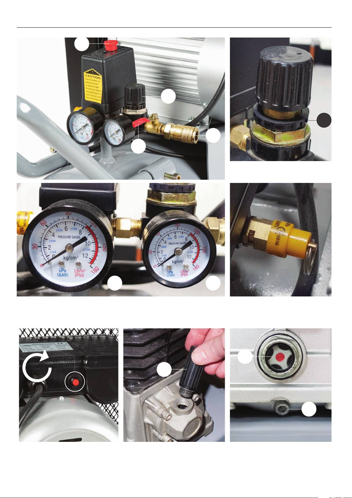
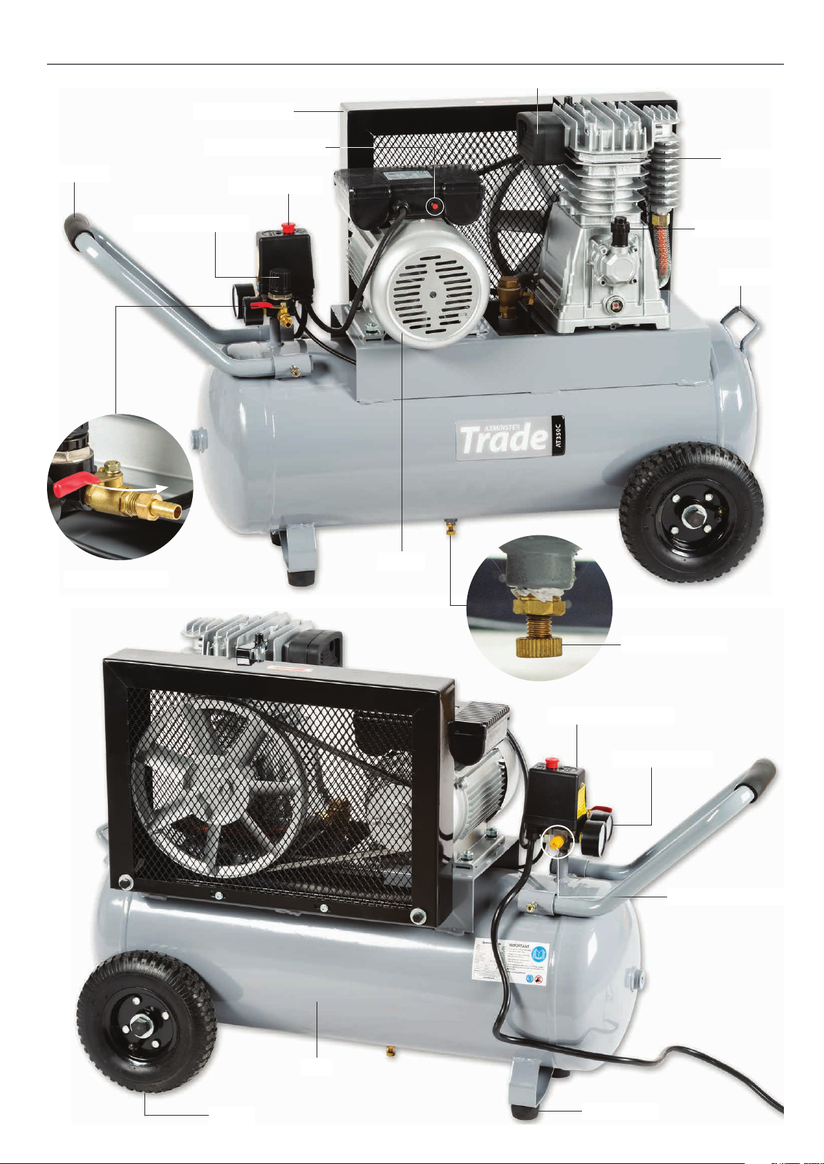
09. Switch the compressor on and off by using the pressure
switch knob (see page 12); only switch off at the mains in
case of emergency.
10. Drain water from tank every day.
11. If the compressor shuts down through overload or
overheating check the reason for the shut-down before
re-starting.
12. Do not adjust the tank pressure relief valve without
reference to Axminster Tools & Machinery Service
Department.
13. Do not remove parts from the compressor whilst it is
running.
14. Do not operate the compressor with protective covers
removed or damaged.
15. When spray painting always work in a well ventilated area
and never close to open flames.
16. Never direct a jet of compressed air towards
people or animals. Keep children and animals away
from the compressor.
17. Do not use on an inclined surface.
18. Only use in ambient temperatures between
–10˚C and +40˚C.
19. Only operate on 230 volt supply and with maximum
fuse rating of 13 amps.

Specification
5
Code 106376
Model AT3050C
Rating Trade
Power 2.2 kW
Free Air Delivered@1 bar - 280 l/m (9.88CFM), @3 bar - 210
l/m (7.41 cfm), @6 bar - 175 l/m (6.18 cfm)
Max Pressure 115 psi
Receiver Volume 50 litre
Oil Capacity 900 ml
Supply Requirements 230 V 1ph 13 A
Overall L x W x H 880 mm x 415 mm x 810 mm
Weight 60 kg
Code 106377
Model AT30100C
Rating Trade
Power 2.2 kW
Free Air Delivered@1 bar - 280 l/m (9.88CFM), @3 bar - 210
l/m (7.41 cfm), @6 bar - 175 l/m (6.18 cfm)
Max Pressure 115 psi
Receiver Volume 100 litre
Oil Capacity 900 ml
Supply Requirements 230 V 1ph 13 A
Overall L x W x H 1,010 mm x 415 mm x 810 mm
Weight 80 kg
AT350C Trade Air compressor AT3100C Trade Air compressor

Assembly
6
Fitting the Rear Wheels
1
2
3
1
2
4
Fitting Handle
B
C
D

Assembly
7
Fitting the Quick Release Coupling Filling the Crankcase with Oil
Remove the 1/4" BSP Male airline fitting, see fig 01. Wrap
some PTFE tape (A) around the thread on the 1/4”BSP male
coupling (B) and screw it into the pressure regulator outlet,
lightly tighten using a spanner. (DO NOT OVERTIGHTEN) The
compressor is now ready for use, see fig 02-03.
01
02
03
06
05
04
A
B
ALWAYS USE COMPRESSOR OIL!
Oil level

Illustration & Parts Description
8
Regulator preset lock (G)
ON/OFF control switch (A), Regulator control knob (B),
1/4”BSP male coupling (C), Outlet Valve Tap (D),
Tank pressure gauge (E), and Outlet pressure gauge (F)
Pressure relief valve
‘REST’ button, press this button if compressor is not functioning properly
Crankcase oil filler plug (H)
Oil Level indicator (I)
Oil drain plug (J)
A
B
C
D
E F
H
G
REST
I
J

Illustration & Parts Description
9
Water drain valve
Outlet valve tap
Oil filler plug
Handle
Air inlet filter
Motor REST control
ON/OFF Switch
Motor
Closed
Open
Crankcase
Handle
Wheel
Pressure relief valve
Pressure switch unit
Pressure gauges
Drive belt guard
Pressure regulator
Rubber foot
Tank

Operating Instructions
10
Turning on the Compressor
Pressure Relief Valve
Connect the compressor to the mains supply and switch on by
pulling the on/off knob upwards. (see figs A-B). Check that the
compressor pressurises the tank and shuts off when the
maximum tank pressure is reached.The compressor is
automatic in operation; the pressure switch shuts the motor
off when the maximum tank pressure is reached and re-starts
it when the pressure drops below a pre-set level.The cut-in
and cut-out pressures are factory set and should not need to
be altered.
CONNECT THE COMPRESSOR
TO THE MAINS SUPPLY!
NOTE: It is advisable to fully drain the air from the tank if
the compressor is left unused for a period, this will prevent
the build-up of water in the tank.
DO NOT use dirty or non detergent oil.
DO NOT operate compressor in an ambient
temperature above 40˚C.
DO NOT operate in a badly ventilated area.
KEEP the air filter clean.
C
A
D
B
Pull up for ON (I) Push down for OFF (O)
There are two safety systems on the air compressor, the first is
the pressure switch to turn the compressor on when the tank
pressure is low and switches off automatically when the correct
pressure is reached. If the switch fails to switch off, the second
is the PRV which should blow open to vent the air from the
tank.This prevents the pressure in the tank from reaching
dangerous levels. A PRV that has let go is a signal that you
need to shut down the air compressor immediately and
contact our technical team to resolve the issue.
Pressure relief valve
Ring TEST the Valve
To test the PRV is working correctly pull the ring towards you, (see fig C-D) this forces the valve to open,venting compressed air
from the tank into the atmosphere. If there is no air in the tank,pulling the PRV ring will not vent air, but it will move the internal
components which is a good thing.

Operating Instructions
11
Output Air Pressure Regulator
The outlet air pressure can be regulated by rotating the
regulator knob clockwise to increase the pressure and
anti-clockwise to reduce it. DO NOT leave the regulator set
at maximum setting unnecessarily; reduce the setting by
about two turns after finishing and then re-set to the
required pressure when starting work again.
0
0
2
4
6
8
10
12
kg/cm2
kPa
(1) 00
•
• (3) 00
•
(9) 00
•
(5) 00
•
(7) 00
(11)00 •
(BAR)
Lb/in2
(PSI)
180
150
30
120
90
60
0
0
2
4
6
8
10
12
kg/cm2
kPa
(1) 00
•
• (3) 00
•
(9) 00
•
(5) 00
•
(7) 00
(11)00 •
(BAR)
Lb/in2
(PSI)
180
150
30
120
90
60
Regulator preset lock
Increase pressure
Decrease pressure

Maintenance
12
Daily:
Weekly:
Drain water from tank, see fig 01.
02
03
04
01
07
08
05
06
DISCONNECT THE COMPRESSOR
FROM THE MAINS SUPPLY!
Check oil level and top-up if necessary, see fig 02-03-04.
Oil level
Monthly:
Remove the air inlet filter outer casing and clean the filter
element, see fig 05-06-07-08.
• Wash in soapy water and leave to dry.
• Do not use the compressor without the air filter fitted.

Maintenance
13
09
Six Monthly: Yearly:
Check the condition of the oil for the following. If you notice the
oil is black insead of a golden colour, a build up of foam inside
the crankcase or water bubbles showing inside the sight glass
level indicator, it’s time to change the oil.
With the oil still warm, place a suitable container under the drain
plug bolt below the sight glass, remove the drain plug and drain
the oil right out, see fig 09. Replace the drain plug bolt, remove
the oil filler plug and refill to the level mark on the sight glass
level indicator, see fig 02.
(1) Replace the air filter element.
(2) Check and clean the air intake and delivery valves.
(3) Check the non-return valve and replace the seal
between the crankcase and cover if necessary.
When components are removed for servicing, take the
opportunity to fit new seals.
Note: (2) and (3) should be undertaken by a competent
service engineer.
Contact our Servicing, parts and technical support team on
0800 371822 or Email: technicalsupport@axminster.co.uk
Hex bolt
Troubleshooting
PROBLEM CAUSE REMEDIAL ACTION
Tank pressure drops Leakage at connections
or joints.
Set the compressor to maximum pressure.
Switch off and brush a soapy water solution
onto all connections and joints. Look for
bubbles. Tighten connections or joints
where leakage is visible.
The pressure switch valve
leaks when the compressor
is stopped
Non-return valve seal
dirty or defective.
Release any air in tank by pulling the ‘PRV’
valve and contact our technical team on
0800 371822.
The compressor stops
and will not start again
Bad electrical connections. Check the connections. Clean and tighten
as necessary.
Current over-load protector or over-heat
protector has activated.
Press the reset button on the current
over-load and wait for a minute.
The motor will run when it has cooled.
Motor winding burnt out. Contact our techical team at Axminster
Tools for assistance.
Compressor head gasket blown or valve
broken.
Contact our technical team at Axminster
Tools for assistance. 0800 371822
The compressor does not reach
the set pressure and overheats
Crank bearing failure. Stop the compressor and contact our
technical team at Axminster Tools for
assistance.
The compressor is noisy
Repetitive metallic clanking
Pressure switch failure. Stop the compressor quickly. Release any
air in tank by pulling the ‘PRV’ valve and
contact our technical team at Axminster
Tools.

Exploded Diagrams/Lists
14
Models: AH-3050, AH30100 Air Compressors

Exploded Diagrams/Lists
15
Models: AH-3050, AH30100 Air Compressors
NO DESCRIPTION QTY
1 Bolt 6
2Spring Washer 6
3 Cylinder Head 1
4 Air Filter Assy 1
5Copper Washer 2
6 In-Six Angle Bolt 2
7 Exht. Elbow Gasket 1
8Spring Washer 2
9 In-Six Angle Bolt 2
10 Exht. Cooler 1
11 Nipple 1
12 Nut,Exhaust 1
13 Gasket, Cylinder Head 1
14 Valve Seat 2
15 Valve Plate 4
16 Gasket, Cylinder 1
17 Piston Ring Set 2
17a Compression Ring 4
17b Oil Ring 2
18 Piston 2
19 Piston Pin 2
20 Piston Pin Clip 4
21 In-Six Angle Bolt 4
22 Spring Washer 4
23 Connecting Rod 2
24 Splasher 2
25 Spring Washer 2
26 Screw,Cross Recess Head 2
27 In-six Angle Bolt 6
28 Spring Washer 6
29 Cylinder 1
30 Gasket, Cylinder 1
31 Breather Assembly 1
32 Washer,Breather 1
33 Gasket, Bearing Cover 1
34 Bearing Cover 1
35 Spring Washer 4
36 In-six Angle Bolt 4
37 Oil Leveler 1
38 Washer, Oil Leveler 1
39 Washer 1
40 Baseplate 1
41 Oil Drain Plug 1
42 In-six Angle Bolt 6
43 Spring Washer 6
44 Crankcase 1
45 Bearing 1
46 Shaft with Elastic Gasket 2
47 Crankshaft 1
48 Woodruff Key 1
49 Bearing 1
50 Gasket, Bearing Seat 1
51 Oil Seal 1
52 Bearing Seat 1
53 Spring Washer 4
54 In-six Angle Bolt 4
55 Pulley 1
56 Pulley Washer 1
57 Spring Washer 1
57a Bolt 1
58 Air Tank 1
59 Pressure Gauge 1
60 Pressure Switch 1
61 Nipple 1
62 Pressure Gauge 1
63 Regulator 1
64 quick coupling 1
65 Safety Valve 1
66 Six Angle Nut 4
67 Washer 4
68 Bolt 4
69 Motor Bolt 4
70 Washer 4
71 Six Angle Nut 4
72 Motor 1
73 Motor Pulley 1
74 In-six Angle Bolt 1
75 Unload Copper Pipe 1
76 Check Vavle 1
77 Unload Elbow 1
78 1
79 Exhaust Pipe 1
80 Protective Fin 1
81 In-six Angle Bolt 4
82 Screw 2
83 Foot Rubber Pad 2
84 Drain Cock 1
85 wheel axle 2
86 wheel 2
87 Six Angle Nut 2
88 Power Cord 1
89 Pres. Adjt Connecter 6
90 Ele.Cable 1
91 V-Belt 1
92 Safety Guard plate 1
93 Washer 1
94 Spring Washer 1
95 Bolt 1
96 Safety Guard 1

Axminster Tools & Machinery
Axminster Devon EX13 5PH
axminster.co.uk
The packaging is suitable for recycling.
Please dispose of it in a responsible manner.
Do not dispose of electric tools together with household waste material.
By law they must be collected and recycled separately.
EU Countries Only
The Axminster guarantee is available on
Craft,Trade, Engineer, Air Tools & CNC Technology Series machines
Buy with confidence from Axminster!
So sure are we of the quality, we cover all parts and labour free of charge for three years!
For more information visit axminster.co.uk/3years
This manual suits for next models
1
Table of contents