Specific Safety Instructions for Planers
7
• Keep the cutting blades sharp and free from resin and
other residue
• Always use a push stick or push block to keep your
fingers away from the cutting block.
• When planing narrow timber ensure that the exposed
part of the Cutterblock is fully guarded.
• Do not attempt to process timber less than 200mm long,
20mm wide or 6mm thick.
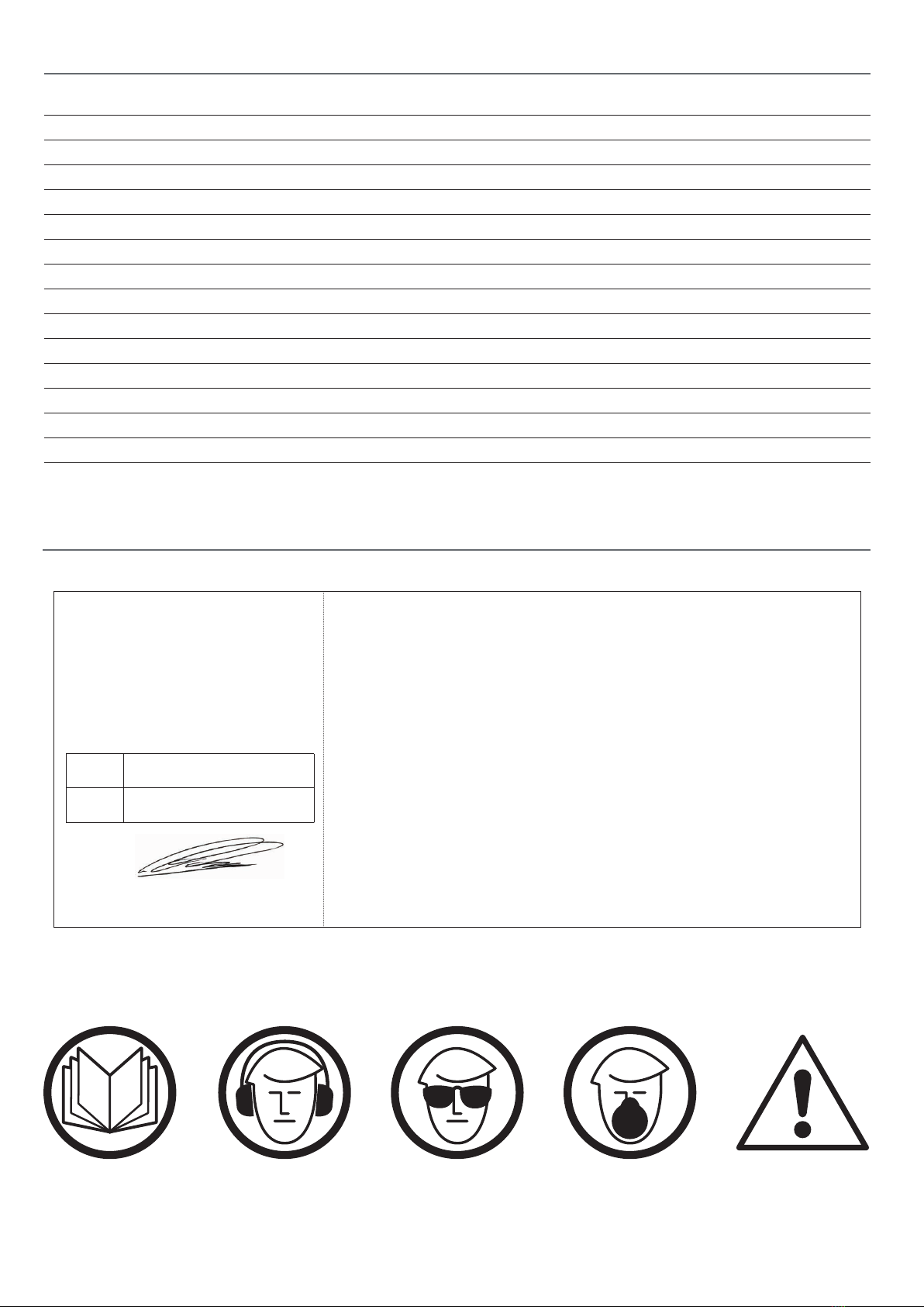
• Maintain the correct relationship between the infeed
table, outfeed table and cutterblock as described in the
operating instructions.
• Always feed the work from infeed to outfeed table
(i.e. from right to left), not the reverse.
• Always plan your work in advance, particularly with
respect to the method of holding and feeding the work
through the machine. Unusual jobs need particular care
and forethought.
• DO NOT make cuts deeper than 1/8” (3mm) in a single
pass. On cuts more than 1/2” (12.7mm) wide, adjust
depth of cut to 1/16” (1.6mm) or less to avoid the wood
from tearing.
• Do not try to cut more than 3mm deep in one pass. The
wider the material, the thinner the cut should be in order
to minimise the load on the motor and the risk of kick
back.
Code 104349
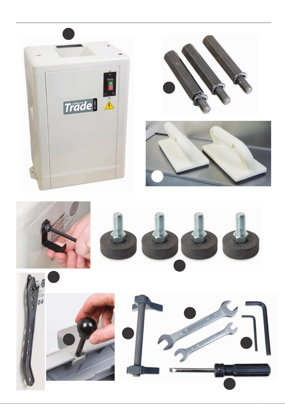
Model AT150SP
Rating Trade
Power 1,120W 230V
Cutterblock Speed 4,200 rpm
Cutterblock Diameter 60 mm
Max Planing Width 150 mm
Max Depth of Cut Planer 3 mm
Knives HSS (Resharpenable) x 3
Noise Level dB(A) 85dB(A)
Fence Size 705 mm x 100 mm
Length of Table 1,422 mm
Table Size 1,422 mm x 150 mm
Min Extraction Airflow Required 1,000 m³/hr
Dust Extraction Outlet 100 mm
Overall L x W x H 1,422 mm x 560 mm x 940 mm
Weight 80 kg
Specification
Code 106240
Model AT150SSP
Rating Trade
Power 1.2 kW
Cutterblock Speed 4,200 rpm
Cutterblock Diameter 60 mm
Max Planing Width 150 mm
Max Depth of Cut Planer 3.0 mm
Knives TC Spur Cutters x 28
Noise Level dB(A) 76dB(A)
Fence Size 705 mm x 100 mm
Length of Table 1,422 mm
Table Size 1,442 mm x 150 mm
Min Extraction Airflow Required 1,000 m³/hr
Dust Extraction Outlet 100 mm
Overall L x W x H 1,422 mm x 560 mm x 940 mm
Weight 80 kg