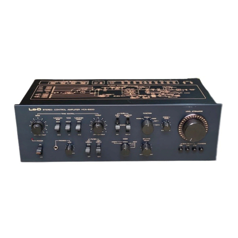
Hitachi HCA-7500 User manual

HCA-7500
STEREO
CONTROL
AMPLIFIER
INSTRUCTION
MANUAL
Congratulations!
HITACHI
Hi-Fi
products
are
the
proud
result
of
HITACHI
engineering
research
and
development
and
over
50
years
of
experience
in
electronics.
Laboratories
and
major
testing
facilities
are
maintained
in
Tokyo
and
Toyokawa
(Japan).
In
choosing
this
fine
HITACH!
Hi-Fi
product
you
have
demonstrated
an
acute
awareness
of
‘getting
the
most
for
your
money”.
With
HITACHI
products
this
is
not
an
idle
boast.
KEY
TO
ILLUSTRATIONS
GS
BOGDOOEQVQOEOHOHVO
POWER
switch
POWER
INDICATOR
LOW
FILTER
switch
HIGH
FILTER
switch
MODE
switch
BALANCE
control
CARTRIDGE
LOAD
selectors
Volume
control
(LEVEL
ATTENUATOR)
MUTING
switch
FUNCTION
switch
TAPE
switch
TREBLE
control
TURNOVER
switches
(BASS,
TREBLE)
TONE
switch
BASS
control
VQPBBW®POSHOoOoQooe
2
Ground
terminal
(GND)
PHONO
1
input
terminals
PHONO
2
input
terminals
TUNER
input
terminals
AUX
input
terminals
TAPE
1
PLAY
terminals
TAPE
1
REC
terminals
TAPE
2
PLAY
terminals
TAPE
2
REC
terminals
OUTPUT
terminals
AC
outlets
(for
U.S.A.
&
Canada
set
only)
Power
supply
cord
VOLTAGE
SELECTOR
(except
for
U.S.A.&
Canada
set)
SAFEGUARD
Electrical
energy
can
perform
many
useful
functions.
This
unit
has
been
engineered
and
manufactured
to
assure
your
personal
safety.
Improper
use
can
result
in
potential
electrical
shock
or
fire
hazards.
In
order
not
to
defeat
the
safeguards,
observe
the
following
instructions
for
its
installation,
use
and
servicing.
ysi|bug

INSTALLATION
When
installing
the
HCA-7500
choose
a
place
that
satisfies
the
following
conditions.
1;
2.
3.
4.
A
place
out
of
direct
sunlight
and
away
from
stoves,
etc.
A
place
where
ventilation
is
good
and
which
is
free
from
moisture
and
dust.
Install
on
a
stable
and
vibration-free
surface.
Hum
noise
is
sometimes
generated
if
the
metal
parts
(like
a
cover)
of
another
audio
component
come
into
contact
with
the
unit,
so
leave
proper
clearances.
Do
not
allow
the
metal
parts
of
another
audio
component
to
come
into
contact
with
the
unit.
TUNER
CASSETTE
DECK
reryxT
a
HABBO
OO
HCA-7500
WARNING:
TO
PREVENT
FIRE
OR
SHOCK
HAZARD,
DO
NOT
EXPOSE
THIS
APPLIANCE
TO
RAIN
OR
MOISTURE.
FEATURES
1.
ICL
Equalizer
Circuit
for
High-Fidelity
Record
Reproduction
The
equalizer
circuit
features
a
3-stage,
direct-coupled
5-transistor
circuit
(differential
FET
for
first
stage,
PNP
differential
transistor,
constant
current
drive
NPN
transistor)
for
a
low
distortion
and
a
high
S/N
ratio,
as
well
as
for
high
stability.
There
are
no
coupling
capacitors
in
the
input
stage
with
the
ICL
(input
capacitor-less}
system,
while
the
output
stage
employs
metalized
polyester
film
capacitors
which
are
non-inductive
and
which
feature
a
superior
high-frequency
response,
These
features
improve
the
frequency
characteristics
and
the
phase
characteristics.
.
RIAA
Elements
with
+1%
Tolerance
Parts
The
RIAA
elements
employ
metal-film
resistors
and
styrol
capacitors
with
a
+1%
tolerance.
These
parts
are
based
on
MIL
standards
and
display
outstanding
temperature
characteristics.
The
RIAA
deviation
across
a
20
Hz
—
20
kHz
frequency
band
is
designed
to
be
less
than +0.2
dB.
.
Low-distortion,
Low-noise
Tone
Control
Circuit
This
is
a
3-stage,
direct-coupled
6-transistor
circuit
(differential
FET
for
first
stage,
constant
current
drive
PNP
transistor
push-pull)
which
not
only
makes
for
low
distortion
and
a
high
S/N
ratio,
but
also
provides
high
stability.
.
Tone
Controls
for
Each
Channel
with
New
Tone
Control
Circuit
The
HCA-7500
adopts
a
new
tone
defeat
control
between
the
bass
and
treble
controls.
Furthermore,
any
de-
viations
in
the
perfect
tone
balance
between
the
left
and
right
channels,
caused
by
the
positioning
of
the
speakers,
for
example,
can
be
compensated
for.
.
Low
Filter
that
Neatly
Cuts
off
Wow
and
Ultra-low
Frequency
Rumble
without
Impairing
Sound
Quality
The
low
filter
can
cut
off
wow
and
rumble
in
the
ultra-low
frequencies
(15
Hz,
12
dB/oct.)
without
impairing
the
quality
of
the
reproduced
sound.
.
New
32-contact
4-gang
Attenuator
Volume
Control
This
control
enables
very
fine
adjustments
across
a
wide
range
of
0
to
70
dB,
yielding
accurate
attenuation
without
producing
any
deviation
between
the
left
and
right
channels.
In
addition,
the
4-gang
volume
control
improves
the
signal-to-noise
ratio
when
set
to
low-volume
levels.
.
Built-in
Muting
Circuit
with
Reed
Relays
The
muting
circuit
is
actuated
for
about
5
seconds
through
the
reed
relays
so
as
to
suppress
shock
noise
when
the
amplifier
is
switched
on.
.
Excellent
Operability,
Sophisticated
Design
All
the
switches
and
the
controls
are
designed
and
positioned
in
keeping
with
the
principles
of
human
engi-
neering
for
optimal
operational
ease.
The
amplifier’s
exterior
is
appealingly
solid
and
sophisticated.
Hitachi
has
managed
to
make
the
operation
of
the
32-contact
attenuator
volume
control
and
all
the
other
front
panel
switches
and
controls
not
only
easy
but
also
accurate.
E-2

Important
for
U.K.:
WARNING:
This
apparatus
must
be
earthed.
The
wires
in
this
mains
lead
are
coloured
in
accordance
with
the
following
code:
Green
and
Yellow
:
EARTH
Blue
:
NEUTRAL
Brown
:
LIVE
As
the
colours
of
the
wires
in
the
mains
lead
of
this
apparatus
may
not
correspond
with
the
coloured
markings
identifying
the
terminals
in
your
plug
proceed
as
follows.
The
wire
which
is
coloured
GREEN
and
YELLOW
must
be
connected
to
the
terminal
in
the
plug
which
is
marked
by
the
letter
E
or
by
the
safety
earth
symbol
+=
or
coloured
GREEN
or
GREEN
and
YELLOW.
The
wire
which
is
coloured
BLUE
must
be
connected
to
the
terminal
which
is
marked
with
the
letter
N
or
coloured
BLACK.
or
coloured
RED.
The
wire
which
is
coloured
BROWN
must
be
connected
to
the
terminal
which
is
marked
with
the
letter
L
CONTROLS
AND
SWITCHES
@
POWER
switch
When
this
switch
is
set
to
ON,
power
is
supplied
to
the
amplifier
and
the
POWER
INDICATOR
@
lights
up.
There
is
a
built-in
muting
circuit
so
that
the
relays
are
actuated
about
5
seconds
after
the
power
has
been
switched
on.
Then
the
amplifier
starts
normal
operation.
(2)
POWER
INDICATOR
This
lights
up
when
the
POWER
switch
(@®
is
set
to
ON.
(3)
LOW
FILTER
switch
When
this
switch
is
set
to
the
15
Hz
position,
low
frequency
noise
which
is
generated
by
warps
in
the
records
is
cut
out.
It
is
wise
to
keep
this
switch
at
the
15
Hz
position
since
it
is
effective
in
cutting
out
low
frequency
noise
outside
the
range
of
hearing
which
can
adversely
affect
the
speakers
(12
dB/oct.).
@
HIGH
FILTER
switch
Set
this
switch
to
the
8
kHz
position
when
you
want
to
cut
out
scratch
noise
from
records,
hiss
noise
from
tapes
and
high-frequency
noise
when
listening
to
a
broadcast.
This
switch
is
designed
to
cut
out
smoothly
the
treble
from
8
kHz
at
6
dB/oct.
©)
MODE
switch
This
switch allows
any
of
five
selections.
STEREO
REVERSE.
.
.This
reverses
the
left
and
right
channels.
NORMAL
..
.This
gives
a
normal
stereo
ef-
fect.
MONO
PR
Vee
oS
The
left
and
right
channel
signals
are
mixed.
RC
eee
Only
the
signals
from
the
left
input
terminals
are
repro-
duced
through
the
left
and
right
speakers.
Res
2
edd
oe
Only
the
signals
from
the
right
input
terminals
are
re-
produced
through
the
left
and
right
speakers.
©
BALANCE
control
Adjusts
the
balance
of
right
and
left
channel
levels.
@
CARTRIDGE
LOAD
selectors
Use
these
selectors
to
set
the
load
capacitance
and
load
resistance
to
levels
that
correspond
to
the
cartridge
which
is
being
used.
The
left-hand
knob
is
for
load
capacitance
settings
(100/200/
300/400
pF)
and
the
right-hand
knob
is
for
load
resistance
settings
{(0.1/10/50/100
k-ohms).
Usually
with
moving
magnet
cartridges,
the
reproduction
characteristics
undergo
great
change
when
the
load
capacitance
and
load
resistance
are
varied.
An
illustration
of
this
is
given
in
the
figure
below.
It
shows
the
charac-
teristics
displayed
when
the
load
capacitance
and
load
resistance
are
varied
when
Hitachi's
MT-202MKIL
cartridge
is
used.
By
selecting
the
load
of
the
cartridge,
the
opti-
mum
values
can
be
chosen
in
line
with
the
characteristics
of
the
cartridge
employing
load
capacitance
and
load
resistance.
When
both
the
load
capacitance
and
load
resistance
of
the
cartridge
being
used
are
specified,
set
the
selec-
tors
to
positions
which
correspond
approxi-
mately
to
these
values.
If
it
is
not
clear
exactly
what
these
values
are,
take
100
pF
and
50
k-
ohms
as
the
reference.
Other
combinations
may
also
be
tried
out
if
they
yield
a
sound
quality
which
meets
the
individual
preference
of
the
listener.
The
0.1
k-ohm
position
for
load
resist-
ance
is
for
high-output
moving
coil
cartridges
(those
which
do
not
require
a
booster
trans-
former).
Do
not
set
the
selector
to
this
position
for
moving
magnet
cartridges.
Response
(dB)
+
-202MKIL
Load
capacitance:
100
pF
position
Cartridge
u:
Ik
2k
Sk
Sk
~~
0k
SCO
Frequency
(Hz)
Response
(dB)
Cartridge
used:
2
Load
resistance
50
k-ohms
position
Ik
2k
5k
10k
20k
40k
Frequency
(Hz)

@)
Volume
control
(LEVEL
ATTENUATOR)
Use
this
to
adjust
the
sound
volume.
It is
con-
figured
as
a
32-contact
attenuator,
and
the
‘0’
position
indicates
the
maximum
output
power.
Attenuation
can
be
provided
in
1
dB
steps
between
O
and
10dB,
in
2dB
steps
between
10
and
22dB,
in
3dB
steps
between
22
and
46
dB,
and
in
4dB
steps
between
46
and
70d8.
The
attenuator
system
guarantees
accurate
sound
volume
adjustments.
@
MUTING
switch
This
switch
is
set
to
ON
when
depressed,
and
an
attenuation
of
20dB
is
provided.
Use
this
switch
when
lowering
the
sound
volume
tempo-
rarily
or
when
finely
adjusting
the
level
to
listen
to
the
sound
at
a
low
volume.
Note:
High-output
signals
will
be
applied
to
the
speakers
when
the
MUTING
switch
is
set
to
OFF,
and
they
may
be
damaged.
Therefore,
always
check
the
position
of
the
volume
control,
or
set
the
control
to
its
minimum
position
(%)
if
you
are
not
sure
of
the
strength
of
the
sound,
before
setting
the
MUTING
switch
to
OFF.
(9
FUNCTION
switch
This
selects
the
program
source.
PHONO-1
...
For
hearing
a
record
on
the
turntable
connected
to
the
PHONO
1
input
terminals
1%.
PHONO-2
...
For
hearing
a
record
on
the
turntable
connected
to
the
PHONO
2
input
terminals
18.
TUNER
....
For
listening
to
a
broadcast
on
a
tuner
connected
to
the
TUNER
input
terminals
79.
AUX
......
For
listening
to
a
program
source
On
a
component
con-
nected
to
the
AUX
input
ter-
minals
2.
4)
TAPE
switch
(See
page
5
for
further
details)
Select
the
switch
positions
as
outlined
below
when
playing
back
a
tape,
when
monitoring
the
recording
state
during
tape
recording,
and
when
dubbing
tapes.
SOURCE
...
For
recording
a
sound
source
selected
by
the
FUNCTION
switch.
TAPE
1.
....
For
monitoring
the
playback
or
recording
of
a
tape
in
tape
deck
1
which
is
connected
to
the
TAPE
1
terminals.
TAPE
2
....
For
monitoring
the
playback
or
recording
of
a
tape
in
tape
deck
2
which
is
connected
to
the
TAPE
2
terminals.
The
following
two
positions
are
used
for
tape
dubbing.
COPY
12...
For
playing
back
a
tape
in
tape
deck
1
which
is
connected
to
the
TAPE
1
terminals
and
re-
cording
the
contents
of
that
tape
onto
a
tape
in
tape
deck
2
which
is
connected
to
the
TAPE
2
terminals
(this
pro-
cess
is
called
dubbing).
At
position
1
the
reproduced
sound
of
the
tape
in
tape
deck
1
can
be
heard,
and
at
position
2
it
is
possible
to
monitor
the
recording
state
of
the
tape
in
tape
deck
2.
COPY
2
D1...
For
playing
back
a
tape
in
tape
deck
2
which
is
connected
to
the
TAPE
2
terminals
and
re-
cording
the
contents
of
that
tape
onto
a
tape
in
tape
deck
1
which
is
connected
to
the
TAPE
1
terminals
(this
process
is
called
dubbing).
At
position
2
the
reproduced
sound
of
the
tape
in
tape
deck
2
can
be
heard,
and
at
position
1
it
is
possible
to
monitor
the
recording
state
of
the
tape
in
tape
deck
1.
42
TREBLE
control
Operate
this
control
after
setting
the
TONE
switch
44
to
ON.
Turning
this
control
to
the
right
from
"0
position
increases
the
treble
and
conversely,
turning
it
to
the
left
decreases
the
treble.
The
treble
can
be
adjusted
+10
dB
at
10
kHz
when
the
TURNOVER
switch
(TREBLE)
4
is
set
t0
3
kHz,
and
£10
dB
at
20
kHz
when
the
same
switch
is
set
to
the
6
kHz
position.
(3
TURNOVER
switches
(BASS,
TREBLE)
Use
these
switches
to
compensate
for
the
acous-
tics
of
the
listening
room
or
the
characteristics
of
the
cartridge.
The
bass
turnover
frequencies
are
150
Hz
and
300
Hz,
while
the
treble
turn-
over
frequencies
are
3
kHz
and
6
kHz.
The
con-
trol
range
is
shown
in
the
following
figure.
aCe.
ay
ot
H
ip
aueaee!
Ah
-
aC
i
ane
wen
A
\
or
Bass
and
Treble
controls
in
center
position
\
Frequency
response
{dB]
Frequency
[Hz]
(4
TONE
switch
Set
this
switch
to
ON
when
you
want
to
con-
trol
the
tone
characteristics,
and
then
proceed
with
the
bass
and
treble
controls.
Setting
this
switch
to
the
DEFEAT
position
yields
a
flat
frequency
response
irrespective
of
the
BASS
@
and
TREBLE
42
controls.
(5)
BASS
control
Operate
this
control
after
setting
the
TONE
switch
4
to
ON.
Turning
the
BASS
contro!
to
the
right
increases
the
bass,
and
turning
it
to
the
left
decreases
the
bass.
When
the
TURN-
OVER
switch
(BASS)
@
is
set
to
300
Hz,
you
can
adjust
the
bass
+10
dB
at
100
Hz
and
when
it
is
set
to
150
Hz,
you
can
adjust
the
bass
+10
dB
at
50
Hz.

LISTING
OF
OPERATIONS
Objective
Connections
FUNCTION
TAPE
switch
()
selector
(0
position
position
Sound
heard
through
speakers/
headphones
TUNER
SOURCE
Reception
of
broad-
casts
Tuner-~
TUNER
terminals
Broadcast
Turntable
>
PHONO
1
or
PHONO
2
termi-
nals
Record
play
Record
Tape
deck
for
playback
>
TAPE
1
terminals
a
do
Tape
playback
Playback
sound
from
tape
deck
1
¢
Tape
deck
1
de-
notes
that
tape
deck
connected
to
the
TAPE
1
SOURCE
terminals
on
the
:
|
Any
position
TAPE
\
rear
panel.
TAPE
2
g
Playback
sound
from
tape
deck
2
SOURCE
Sound
of
source
selected
by
FUNCTION
switch
TAPE
Sound
recorded
on
tape
deck
1
can
be
monitored.
Tape
deck
for
playback
>
TAPE
2
terminals
Recording
(broad-
Tape
deck
for
re-
casts,
records)
cording~™
TAPE
¢
The
recording
level
1
and/or
TAPE
2
is
adjusted
with
the
terminals
tape
deck’s
record-
ing
level
controls.
a)
Tape
dubbing
(1D
2)
(Recording
a
broadcast)
I
(Recording
re-
cords)
PHONO
-1
TAPE2
|
Sound
recorded
on
tape
deck
2
can
be
monitored.
rN
Qo
é
n
Any
positio
apis
Playback
sound
1
ra
S
<
from
tape
deck
1
Sound
recorded
Set
to
recording
sound
source
Tape
deck
for
playback
>
TAPE
1
terminals
Tape
deck
for
recording
>
TAPE
2
terminals
on
tape
deck
2
can
be
monitored.
Tape
deck
for
playback
->
TAPE
2
terminals
Tape
deck
for
recording—>
TAPE
1
terminals
paler
Playback
sound
an!
of
tape
deck
2
sob
Sound
recorded
a
zy
|
on
tape
deck
1
12
.
can
be
monitored.
Playback
sound
of
tape
deck
1
¢
The
recording
sound
can
be
monitored
when
the
TAPE
switch
is
set
to
TAPE
2.
Tape
deck
for
playback—>
TAPE
1
terminals
Tape
deck
for
recording
>
TAPE
2
terminals
Recording
of
a
broadcast
or
records
during
tape
play-
back
Tape
deck
for
playback
—>
TAPE
2
terminals
Tape
deck
for
recording->
TAPE
1
terminals
TAPE
2 |
Playback
sound
of
tape
deck
2
¢
The
recording
sound
can
be
monitored
when
the
TAPE
switch
is
set
to
TAPE
1.
The
programs
you
record
may
be
used
for
your
own
personal
entertainment
but
copyright
laws
prohibit
use
without
permission
for
personal
gain.
E-5

WHAT
TO
DO
IF?
There
can
be
a
variety
of
problems
due
to
the
mis-handling
of
the
control
amplifier.
When
a
problem
occurs,
please
check
the
table
below
which
describes
possible
problems
occurring
in
your
con-
trol
amplifier.
Since
the
contro!
amplifier
is
completely
checked
and
adjusted
before
shipping,
there
are
no
user
serviceable
and
adjustable
parts
inside.
But
if
the
control
amplifier
is
not
operating
correctly
and
you
are
unable
to
restore
nor-
mal
operation
by
following
the
detailed
procedure
in
the
table
below,
do
not
remove
the
back
cover
of
the
set
or
attempt
any
further
adjustments.
Unplug
the
sét
and
contact
your
dealer
or
nearest
Hitachi
service
station.
SYMPTOM
a
REMEDY
Power
indicator
does
not
come
Line
plug
is
loose.
1.
Plug
the
AC
plug
into
AC
outlet.
on
and
the
sound
is
not
heard
Fuse
blown.
2.
Replace
the
fuse.
although
the
power
switch
is
set
to
ON.
Power
indicator
comes
on
but
the
sound
is
not
heard.
1.
The
speaker
cords
are
loose.
3
2.
The
tape
switch
is
set
to
TAPE-1
or
TAPE-2.
The
speaker
cord
of
one
channel
is
loose.
2.
BALANCE
control
is
turned
fully
clockwise
or
counterclock-
wise.
Sound
separation
is
not
distinct
Polarities
of
the
speaker
connec-
Correct
the
polarities
on
either
the
and
bass
is
poor.
tions
are
not
aligned
properly.
"speakers,
The
sound
of
both
channels
or
Faulty
connection
of
the
output
Connect
the
output
cords
of
the
turn-
one
channel
is
not
heard.
cords
of
the
turntable.
table
to
the
control
amplifier
securely.
Hum
and
buzz.
.
Faulty
connection
of
the
output
1.
Connect
the
output
cords
of
the
turn-
cords
of
turntable.
table
to
the
control
amplifier
securely.
2.
Pin
jack
connection
is
loose.
2.
Secure
the
pin-plug
to
the
pin-jack.
3.
Ground
wire
is
loose.
3.
Connect
the
ground
wire
of
the
turn-
4.
There
is
a
line
cord
near
the
out-
table
to
GND
terminals
of
the
control
put
cords
of
turntable.
amplifier.
4.
Separate
the
line
cord
from
the
output
cords
of
the
turntable.
Connect
the
speaker
cords
to
the
speaker
terminals.
2.
Set
the
tape
switch
to
SOURCE.
1.
ie
Only
one
channel
works.
Connect
the
speaker
cord
to
the
speaker
terminals.
2.
Set
the
BALANCE
control
to
the
mid-
way
position.
NORMAL
PLAYING
Increasing
the
volume
causes
howl.
1.
Sound
of
the
speakers
is
making
the
turntable
vibrate.
1.
Move
either
the
speakers
or
turntable.
Do
not
increase
the
BASS
sound
level
excessively.
PLAYING
RECORDS
Output
tone
is
mixed
with
noise
and
treble
is
not
clear.
1.
Stylus
is
worn
out.
2.
Record
is
worn
out.
3.
Dust
is
adhering
to
stylus.
4.
Stylus
is
improperly
mounted.
5.
Tracking
force
is
not
correct.
6.
The
TREBLE
sound
is
too
high.
1.
Static.
2.
Noise
caused
by
other
electric
appliances.
Correct
the
conditions
described
in
1-6.
Continuous
noise
in
AM.
Set
up
a
good
and
high
outdoor
antenna
and
ground
it
perfectly.
Only
when
tuning
AM
broad-
1.
casts,
hum
noise
is
heard.
Generally
caused
by
high
voltage
By
reversing
the
polarity
of
AC
plug,
lines
or
other
electric
appliances.
the
hum
is
reduced,
But
it
is
very
diffi-
cult
to
remove
this
noise
completely.
Continuous
or
intermittent
noise.
1.
Ignition
noise
from
automobile
engines.
Set
up
an
outdoor
FM
antenna
in-
stead
of
using
attached
FM
feeder
antenna.
The
sound
of
FM
program
con-
tains
noise
like
zzz.
More
noise
is
included
in
FM
stereo
recep-
tion
than
FM
mono.
1.
The
signal
input
of
antenna
ter-
minals
is
too
weak
to
receive
FM
stereo
broadcasts.
Set
up
an
outdoor
FM
antenna.
LISTENING
TO
BROADCASTS
Operation
procedure
for
power
switches
The
HCA-7500
incorporates
a
muting
circuit
to
safeguard
against
shock
noise.
Nevertheless,
you
can
still
damage
your
speakers
if
you
operate
the
amplifiers
carelessly,
so
be
sure
to
follow
the
procedure
outlined
below.
Switching
the
power
on
Switching
the
power
off
Control
amplifier’s
volume
control
Minimum
|
Control
amplifier’s
volume
control
Minimum
Power
amplifier’s
speaker
switch
OFF
|
Power
amplifier’s
speaker
switch
OFF
Control
amplifier’s
power
switch
ON
|
Power
amplifier’s
power
switch
OFF
Power
amplifier’s
power
switch
ON
|
Contro!
amplifier’s
power
switch
OFF
Power
amplifier’s
speaker
switch
ON

SPECIFICATIONS
Preamplifier
Input
sensitivity
({mpedance)
Overload
level
(1
kHz,
T.H.D.
0.01%)
Output
level
({mpedance)
Max.
output
level
Frequency
characteristics
Signal-to-noise
ratio
(WHF,
short-circuited,
A
network)
Residual
hum
and
noise
Harmonic
distortion
(20
Hz
—
20
kHz)
Tone
control
Filter
Muting
Power
supply,
others
Power
supply
Power
consumption
Dimensions
Weight
PHONO
1,2:
2
mV
(0.1
k-ohm,
10
k-ohms,
50
k-ohms,
100
k-ohms/
100
pF,
200
pF,
300
pF,
400
pF)
TUNER/AUX:
100
mV
(50
k-ohms)}
TAPE
1,
2:
100
mV
(50
k-ohms)
PHONO
1,
2:
350
mV
TUNER/AUX:
More
than
10
V
TAPE
1,2:
More
than
10
V
PRE
OUT:
1
V
(600
ohms)
TAPE
REC
OUT:
100
mV
(600
ohms)
PRE
OUT:
More
than
7
V
PHONO
1,
2
(RIAA):
20
—
20,000
Hz
(+0.2
dB)
TUNER/AUX:
5
—
100,000
Hz
(*9
dB)
PHONO
1,2:
87
dB
(input
level
2
mV)
TUNER/AUX:
100
dB
(input
level
100
mV)
TAPE
1,2:
100
dB
(input
level
100
mV)
PRE
OUT:
8yuV
PHONO
1,
2:
Less
than
0.005%
at
REC
OUT
level
1
V
Less
than
0.01%
at
REC
OUT
level
5
V
TUNER/AUX:
Less
than
0.005%
at
PRE
OUT
level
1
V
Less
than
0.01%
at
PRE
OUT
level
5
V
BASS:
£10
dB
(50
Hz,
100
Hz
turnover
at
150
Hz,
300
Hz}
TREBLE:
+10
dB
(10
kHz,
20
kHz
turnover
at
3
KHz,
6
kHz)
LOW:
15
Hz
(12
dB/oct.)
HIGH:
8
kHz
(6
dB/oct.)
-20
dB
AC
120
V,
~220
~—
240
V,
50/60
Hz
12
W
(AC
120
V,
220
V
—
240
V)
480
(W)
x
166
(H)
x
348
(D)
mm
78kg
17.2
Ibs.
Specifications
and
designs
may
be
changed
without
notice
for
improvement.


Phono
Input
vs.
Distortion
Rate
Characteristics
Frequency
Characteristics
Plattenspielereingang
im
Vergleich
zum
Gesamtklirrfaktor
Frequenzgang
Courbes
caractéristiques
de
l’entrée
phono
sur
le
taux
de
distorsion
Réponse
en
fréquence
(Dem
L
Tt
14
Input
:
PHONO
|
terminal
S
Input
-
TUNER
terminal
op
+t
ath
Oitsaee
BER
terainal
am
&
22
Output
:
OUTPUT
terminal
-
Fe?
Sere
ttt
alae
SS
on
O
dB
:
0.775V
ms
is
Toa
mannii
Eingang
:
Plattenspielerbuchse
|
S
:
—-
-4
4
HH
}
FT
PHONG
ed
§
2
09
Eingang
:
TUNER-Buchse
@
2a
~tLow
ter
ett
Pet
tot
i
A
568
Ausgang
:
Ausgangsbuchse
Fes
ON
fp}
ppt
et
Ay
+
Ausgang
:
Aufnahmebuchse
(REC)
Zs
&
902
eet
gsbuchs
3
S
3
Tieten
iter:
=
High
filter
ONE
the
ole
Ns
Hohen
filter
ON-+
:
a3
ae
seer
nfl
Entrée
:
Bornes
PHONO
!
°
2
E
0.04
O
dB:
0,
775V
2
“4
3
‘6
passe-bas
aa
tala
Filtre
passe-haut
ON
TY
TTT
Co
a
em
-—1nk
iH
1
ec
cuc
ON
Th
t
Sortie
:
Bornes
REC
EE
7
0.00
Entrée
:
Bornes
TUNER
Poa
oor
|
mais
At
28
Sortie
:
Bornes
OUTPUT
|
ee
LL
=ge
PAGE
Hay
ali
O
dB:
0,775V
-is
Jot
i
ET
i
HE
wo
i
f
i
PSG
°°
7s
id
20-50
100
200
500
10002000
5000
1
2
5
10
2
SO
Ik
kG
5k
10k
“a
50k
100k
F
Hz)
F
Hz)
Fré
H
input
voltage(mV
)
Eingangsspannung(mV
)
Tension
entrée(mv
}
requencytH2z}
Frequenz(Hz)
Fréquence(Hz)
Equalizer
Allowable
Input
Characteristic
dite
it
EIN
ee
ac
I
Bs
Heir
vison
oll
oat
lees
kar
ONE
Zulassiger
Eingangspegel
des
Entzerrers
|
Audio
Ose
:
A
onfrequenzgenerator
:
Mode
P-721A
|
Ree
a
basse
fréquence
:
Modéle
VP-721A
|
AC
Voltmeter:
MODEL
3400A
|
Wechselstrom-Voitmeter
:
Modei!
3400A_
|
Pes
-
a
.
;
oltmétre
CA:
Modéle
3400A
Courbe
caractéristique
d’entrée
permise
du
compensateur
in
ean
aha
con
i
At
RPL
tC
Sree
Secs
ae
ak
:
—
ee
hy
Input
:
PHONO
I
terminal
5000
(level
2mV)
-
Output
-
REC
terminal
=
200'—}-+-}
Distortion
rate
:
0.01%
constant
age
ee
o
~
Eingang
:
Plattenspielerbuchse
|
£
2
500
(PHONO
|)
(Pegel
2mV)
faz
Ausgang
:
Aufnahmebuchse
(REC)
~
SS
204
.
is
<c
Gesamtklirrfaktor
:
0,01%
konstant
Bit
=
10
mn
a
ann
ae
o
=
Entrée
:
Bornes
PHONO
!
24°
sak
tai
(aiveats
Dawe
3
2
@
i
RIAA
Deviation
Sortie
-
Bornes
REC
e364
Dove
piavinr
du
déviation
RIAA
F
:
%
constant
|
I
eristtque
du
viation
Taux
de
distorsion
:
0,01%
Wea~ag
BOI
BOO
UBT
ZUR
5K
100K
:
Frequency(Hz)
Frequenz(Hz)
Fréquence(Hz}
Input
>
PHONO
|
terminal
<3
(level
2mV)
n@n
Output
vs.
Distortion
Rate
Characteristics
Output
:
REC
terminal
SS
403
ato
:
Ausgangsleistung
im
on
zum
lah
apne
etuicuecdicneiciee
Eingang
;
Plattenspielerbuchse
|
E
2
g
$0.2
;
roe
=
tt
HT
|
Courbes
caractéristiques
de
a
puissance
ee
sortie
su
(PHONO
|)
(Pegel
2mV)
©
Sm
0
fet
—
_LUTT:
Input
:
TUNER
terminal
&
2
Ausgang
:
Aufnahmebuchse
a2
$2.
Lie
LT
Ts
Output
+
OUTPUT
terminal
XS
zg
ol
(REC)
Se
a
319-20
501000000
2B
10k
OK
50K
100K
Eingang
:
TUNER-Buchse
6
Entrée
:
Bornes
PHONO
|
cra
Frequency(H2}
Frequenz(Hz)
Fréquence(Hz)
Ausgang
:
Ausgangsbuchse
BY8
(niveau
2mV)
(OUTPUT
)
g.5
Sortie
:
Bornes
REC
fe
Entrée
:
Bornes
TUNER
es
5
Sortie
:
Bornes
OUTPUT
Efc
aon.
22%
:
a
“Pett
—
©
5
0.002
t
SEs
HT
|
ele
So
©
2
4
og
iLL
Liiiul
bri
i
Foot
0.02
0050702
05
1
2
5
W
20
50
100
Power
output(V)
Ausgangsieistung(V}
Purssance
de
sortie(v}
7
~-Measuring
Equipment
-—--—
—\
;~~Mefgerate-
=e
¢-7Equipement
de:
mesures
Hh
Audio
Osc.:
MODEL
4494A
i!
Tonfrequenzgenerator
>
Modell
44944
|
\
Générateur
a
basse
fréquence
:
Modéie
4494A
:
;
AC
Voltmeter:
MODEL
34004
Wechselstrom-Voltmeter
:
Mode!l
3400A
°
|
Voltmétre
CA
:
Modéle
3400A
:
|
Dtstortion
Meter:
MODEL
43334
;
|
Klirrfaktormesser
:
Model!
4333A
:
|
Appareil
de
mesure
:
Modéle
4333A
i
Rae
Salis
ies
a
ae
Gis
gcse
atc
at
ee
MVE
er
a,
acca
fab
anioa
dae
a
4764411
Printed
in
Japan’
H)

~HCA-7500
eer
®D
STERECACONTROL
AMPLIFIER
HCA-7500
LEVEL
ATTENUATOR
‘ONE
CONTROL
TAPE
FUNCTION
TURNOVER
TONE
TURNOVER
,
20
9220
wy
*
BASS
TREBLE
SOURCE
PHONG
——
5
“
Ms
sa
TAPE-1
300rE
oOEreat
;
™N
ai
ieeememmmene
|
r-FILTER
Low
HIGH
i
leles
poe
:
(asvoct)
(8@B/oct
stEREO
NORMAL
MONO
CARTRIDGE
LOAD
POWER
1Brtz
Orr
c=
REVERSE
Ler
H
ex
Besse
guna
;
Sa
ee
vet
: :
«40
.
i
c
’
¢
she
STEREO
POWER
AMPLIFIER
eee
power
plug
after
you
have
finshed
STEREO-ENDVERSTARKER
Always
use
a
household
AC
outlet
as
the
AMPLIFICATEUR
DE
PUISSANCE
STEREO
Dewey
A
Mpulley's
POMEL
SONGS:
Als
Stromquelle
des
Endverstarkers
stets
eine
Netzsteckdose
ver
wenden.
Nachdem
alle
Anschllsse
vorgenommen
wurden.
den
HCA-7500
ans
Netzanschliefen.
Ne
raccorder
la
prise
d’alimentation
du
HCA-7500
que
lorsque
‘
Utiliser
toujours
une
prise
ran
vous
aurez
achevé
toutes
les
connexions.
)
p
de
courant
CA
domestique
comme
source
d’alimentation
de
Vamplificateur
de
puissance.
AM/FM
STEREO
TUNER
UKW/AM
STEREO-
TUNER
TUNER
STEREO
AM/FM
—
AC
outlets
:
The
HCA-7500
has
two
SWITCHED
TOTAL
100
W
MAX
outlets
and
two
UNSWITCHED
TOTAL
200
W
MAX
outlets.
(for
U.S.A.
&
CANADA
sets
only.}
at
;
:
Wechselstromausgange
:
Der
HCA-7500
besitzt
zwei
geschaitete(
SWIT-
CHED)
Ausgange
von
insgesamt
100
W
maximal
und
zwei
ungeschaltete
(UNSWITCHED)
Ausgange
von
insgesamt
200
W
maximal.
(Nur
bei
Gerdten
flr
U.S.A.
und
KANADA)
Sorties
CA:
Le
HCA-7500
posséde
2
sorties
commutables
totales
de
100
Watts
maximum
et
2
sorties
non-commutables
de
200
Watts
maximum
a
pour
les
appareiis
vendus
seulement
aux
U.S.A.
et
au
Canada).
Jd
VOLTAGE
SELECTOR
STEREO
CONTROL
AMPLIFIER
I.
ea
cake
|
a
-240V~
MODEL
Ne.
HCA
—7500
'
3
ACi@0
VOLTS
BOHz
:
“
1@
WATTS
Min
ac
A
BOVES
DE
CHOC
ELECTRIGEE,
NE
PAS
HItACHy,
Lite.
Tokyo
Jaman
RETINER
LES
VIS.
AUCUNE]
[TECH
W'EST
REMPLACABLE
PAR
LA
CLIENTELE
MAGE
IN-SADAN
ELLE-MEME.
CONSULTER
U1
E
PE)
BONNE
QUALIFIEE
POUR
LES
REPARATIONS.
Any
hum
caused
when
the
power
amplifier
is
installed
near
this
model
\
can
be
reduced
by
unplugging
the
power
plug
of
the
control
amplifier
Earth
wire
and/or
power
amplifier,
turning
it
upside
down
and
plugging
it
in
again.
Erdung
Falls
dieses
Gerat
in
der
Nahe
des
Leistungsverstarkers
aufgestellt
Fil
de
prise
wird
und
Brummgerausch
zu
horen
ist,
den
Netzstecker
von
Steuerver-
p
starker
und/oder
Leistungsverstarker
herausziehen
und
in
umgedrehter
GaN
tereS
Steliung
wieder
einstecken.
Dadurch
wird
im
aligemeinen
das
Brummen
reduziert.
On
peut
réduire
un
ronfiement
quelconque
apparaissant
quand
lampiifi-
cateur
de
puissance
est
placé
prés
de
ce
modéle,
en
débranchant
la
prise
d’alimentation
secteur
de
|'amplificateur
de
commande
et/ou
de
\‘amplificateur
de
puissance,
puis
en
le
retournanit
complétement
une
fois
et
en
le
rebranchant.
)
(TAPE
|
and
2
PLAY
terminals
are
provided
with
shorting
pin
plugs.
}
Remove
all
plugs
when
using
terminals.
When
the
TAPE-1
or
TAPE
-2
PLAY
terminals
are
not
being
used.
return
the
shorting
pin
plugs
to
thew
original
posittons.
Die
Ausgangsbuchsen
flr
Tonbandgerate
TAPE
|
und
2
sind
mt
Kurz-
schlugsteckern
versehen.
Bci
Verwendung
aller
Anschiu@buchsen
alle
Kurzschlustecker
entfernen.
Wenn
die
Anschlu@buchsen
“TAPE-
|"
und
“TAPE-2
PLAY”
micht
benutzt
werden,
die
Kurzschlu@stecker
wieder
in
die
Buchsen
siecken.
TAPE
DECK
|
Les
Bornes
TAPE-1
et
TAPE-2
PLAY
sont
équipées
de
fiches
de
TURNTABLE
TONBANDGERAT
mise
en
court-circuit.
Retirer
toutes
les
fiches
quand
vous
utilisez
ces
MAGNE
TOPHONE
bornes.
Lorsque
les
bornes
TAPE-|
ou
TAPE-2
PLAY
ne
sont
pas
PLATTENSPIELER
utilisées,
remettre
les
fiches
a
broches
de
court-circuit
sur
jeurs posi-
TOURNE-DISQUE
\_
tions
initiales.
a.

Mo3e
Volume
control
PTD
Be
ee
Re
ent
ee
a
ee
7
7
High
filter
sw.
pA
ii
a
Balance
Mode
sw
:
Output
terminal
7
/
Function
sw
Low
filter
sw.
TUNER
Tone
amp
PHONO1
Filter
amp.
Muting
Power
sw
ACI20V
60Hz
~220V
—240V
soHz
1
AG
a
©
A:
UNSWITCHED
SWITCHED
TOTAL200W
TOTALIOOW
+32v
—32v
DC
stabilized
power
source
ee
U.S.A.
a
Canada
set
only
©
Hitachi,
Ltd.
Tokyo
Japan
Head
Office
:
5-1,
1-chome,
Marunouchi,
Chiyoda-ku,
Tokyo,
Japan
Tel.
>
Tokyo(212)1111(80
lines)
Cable
Address
:
“HITACHY”
TOKYO
O37
A
Table of contents
Other Hitachi Amplifier manuals

Hitachi
Hitachi HA-6800 User manual

Hitachi
Hitachi HMA-7500 User manual

Hitachi
Hitachi HA-330 User manual

Hitachi
Hitachi HA-M33 User manual

Hitachi
Hitachi HA-3700 User manual

Hitachi
Hitachi HMA-6500 User manual

Hitachi
Hitachi IA-1200 User manual

Hitachi
Hitachi HMA-750 MK2 User manual

Hitachi
Hitachi HCA-6500 User manual

Hitachi
Hitachi HTA-12 User manual

Hitachi
Hitachi HMA-8300 User manual

Hitachi
Hitachi HA-7700 User manual
Hitachi
Hitachi HTA-4000 User manual

Hitachi
Hitachi HA-5300 User manual

Hitachi
Hitachi HA-2800 User manual

Hitachi
Hitachi HMA-8300 User manual

Hitachi
Hitachi HCA-8300 User manual

Hitachi
Hitachi HA-7700 User manual

Hitachi
Hitachi HA-M44 User manual

Hitachi
Hitachi HCA-8500Mk2 User manual