Axxent GPX 2500 User manual

Mixer/Amplifier GPX 2500
®
Operation Manual
axxent e.K. · Technologiezentrum Herzbachtal · Zum Wartturm 15 · 63571 Gelnhausen (Germany)
1
2
3
GPX-2500 setup and operation
When opening the box, you should nd:
• The mixer GPX-2500
• The 19" rack mount brackets (pre-installed)
• Equalizer protective cover plate (pre-installed)
• Two adapters: phone/RCA for the front line inputs
• Powercord
Unit dimensions:
435 mm x 280 mm x 88 mm (without rack mount brackets)
Weight: 10.4 kg net, 13 kg shipping
After unpacking the mixer please plug in the delivered
power cord into the power input jack of the unit. Before
connecting the mixer to the wall outlet, make sure that the
"POWER" switch on the right of the front side is in "OFF"
position. Also the main volume control (MASTER) should
be set fully counterclockwise ("0" position).
Attention: Due to safety reasons the case never should
be opened by the user. Beside, this also may void any
warranty claims!
Now you may connect the mixer to a wall mains outlet.
Please make sure you rst switch on the GPX-2500 and then
the power amplier. This way you avoid annoying audible
transient noise.
On the left hand side you will nd the 3 pin XLR female con-
nectors (1), the microphone inputs for connecting balanced
microphones. Close by on the right is a recessed push
button (2) for activation of phantom power when using
condenser microphones. When dynamic microphones
are hooked up, the switch remains in the "OFF" position.
Please note, that the microphone inputs on the front and
on the rear side are used in parallel. This means that you
may either use the front- or the rear inputs, not both of the
XLR input pairs simultaneously.
Beneath the XLR inputs you will nd two 1/4" phone jack
inputs (3). These are line level inputs, for example to con-
nect a stereo keyboard or a device for playback music. The
left phone jack is a stereo type (TRS) e.g. tip = left chan-
nel, ring = right channel input. When
using mono phone plugs connect
left and right plugs as printed on the
housing. In case you want to use a
cable with RCA connectors, we have
enclosed two suitable adapters in the
packaging for your convenience.
controls on the front side

Mixer/Amplifier GPX 2500
®
Operation Manual
axxent e.K. · Technologiezentrum Herzbachtal · Zum Wartturm 15 · 63571 Gelnhausen (Germany)
4 5 6 7 8 9 10
Each of the three front inputs provides a 3 band equalizer
(4), "LOW, MID and HIGH" and a volume level control (5).
Located right from the volume controls is the 5 position
source select switch (6) (SELECT). With this rotary knob
you easily can select any of the 5 RCA stereo inputs on the
rear side of the mixer, labelled AUX1 to AUX5. Typically
these inputs are used to connect CD/MP3 player, cassette
player, tuner or similar devices. Right of the source selector
knob you will nd the volume control (7) for the selected
source.
In the middle of the front panel you surely will see the
protection plate, covering the 7 band equalizer. Reason for
this cover plate is to protect the equalizer settings made
by an acoustic engineer after
calibrating the complete system.
If you may want to make your
own sound adjustments, and no
calibration settings by an acous-
tical expert must be protected
against unwanted changes, feel
free to remove this metal cover
plate. The gain range of the
equalizer is limited to ± 6 dB
by intention in order to avoid
extreme setting which may result in an unwanted "twisted"
frequency response and also may cause damage to the
system or components.
On the right hand side of the GPX-2500 you will see the
output volume controls, one for the "MASTER" (9), the main
stereo output, and two smaller control knobs (8) for adjust-
ing the level of the two mono zones. For example the
stereo main output may be used in a pub or bistro to drive
the main loudspeakers, a zone output for the washrooms/
hallways and another one for separate smaller room. The
balanced XLR output jacks for the mentioned dierent
PA areas are located on the rear side. Above the "MASTER"
volume control you see a row of three LED indicators (10)
for power on, signal presence and for the limiter activity.
Limiter: Located on the right bottom side of the front
panel you see two recessed controls for the limiter, one is
the on/o switch and the upper is the screwdriver adjust-
able setting for the limiter attenuation level. The limiter is
an important tool to keep the sound pressure level (SPL)
within a prexed maximum, for example
if government rules do not allow SPLs
above a certain maximum level. With
this limiter you can rest assured that this
maximum level is not exceeded–and
you even can have this maximum level
measured and calibrated by an acoustic
engineer and have it ocially sealed.
The output level of the GPX-2500 may
be attenuated up to 30 dB. Last not least above the limiter
section you may have already noticed the "POWER" switch.
No further explanation necessary here...
Mixer/Amplifier GPX 2500
®
Operation Manual
axxent e.K. · Technologiezentrum Herzbachtal · Zum Wartturm 15 · 63571 Gelnhausen (Germany)
1243 5 76
DECLARATION OF CONFORMITY
We declare as our sole responsibility that this product is in compliance with the
EMC Directive 89/336/EEC and conforms to the requirements of the Harmonized
Product Standards EN 55013 (Product Emissions), and EN 55020 (Product Immu-
nity).
Connections on the rear panel
Left hand side on the bottom is the mains fuse holder (2)
and the fuse switch (1). Should the fuse really gets blown,
please replace it with a fuse of the same type (6.3 A, slow
blow). Should this happen again do not use another
"stronger" type of fuse or unscrew and open the unit.
In this case please call your dealer or installer for repair.
We already mentioned the ve RCA stereo aux inputs
(4) on the rear panel. Left from these you will notice RCA
jacks labelled "REC" (3). These are, we think you guessed
it, intended for recording purposes (tape-/cassette recorder
etc.).
Above these RCA jacks are the XLR outputs. "RIGHT" and
"LEFT" (5) are the stereo main outputs, the other two the
mono outputs for ZONE 1 and ZONE 2. Right hand on the
bottom are the XLR microphone inputs (6), connected in
parallel wit the corresponding inputs on the front side
(only use either one!)
The GPX-2500 is delivered from factory with ready installed
rack mounts ("ears") for mounting in a standard 19" rack.
These rack mounting brackets are easily detachable for set-
ting up the mixer on a table or any other surface.
Now there is nothing left but wishing you trouble free opera-
tion of the GPX-2500. Enjoy the excellent sound it delivers.

Mixer/Amplifier GPX 2500
®
Operation Manual
axxent e.K. · Technologiezentrum Herzbachtal · Zum Wartturm 15 · 63571 Gelnhausen (Germany)
1
2
3
MIC1
GND
S1
+48V
-50dBV -20dBV
GND
1
2
3
MIC2
GND
S1
+48V
-50dBV -20dBV
GND
0dBV -20dBV
GND
AUX1AUX2AUX3AUX4AUX5
1
2
3
4
5
6
7
5W AY
1
2
3
4
5
6
7
5W AY
7EQ-L
7EQ-R
GND
GND
GND
GND
LIMITER-L
LIMITER-R
OUT- L
OUT- R
GND
GND
GND
ON/OFF
ON/OFF
SEPARATE Z1
GND
0dBV
0dBV 0dBV
1
1
1
GND
ON
AC230V
+48V
+15V
GND
-15V
GND
AC/DC
PO WER
SIGNAL LIMIT
GND
SEPARATE Z2
GND
+/-6dB
+/-6dB
+/-6dB
+/-6dB
+/-6dB
LINER
J7
J6
LINEL
-10dBV
POWER
1
1
POWER
1
1
OUT 4ohm
POWER
1
1
POWER
1
1
OUT 4ohm
OUT 4ohm
OUT 4ohm
+U P
GND
-U P
AC/DC
POWER
MIX
Block Diagram, Pro Power Mixer GPX2500
Table of contents
Other Axxent Amplifier manuals

Axxent
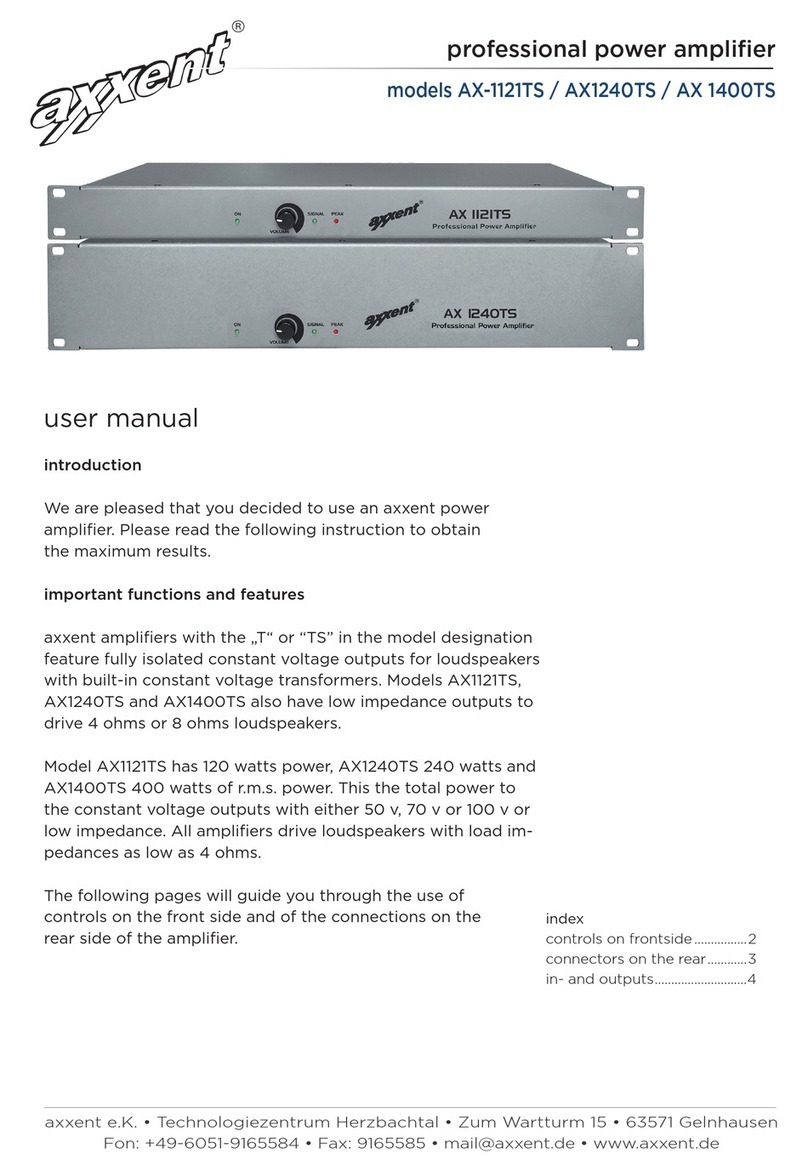
Axxent AX-1121TS User manual

Axxent
Axxent ISV 1090 User manual

Axxent
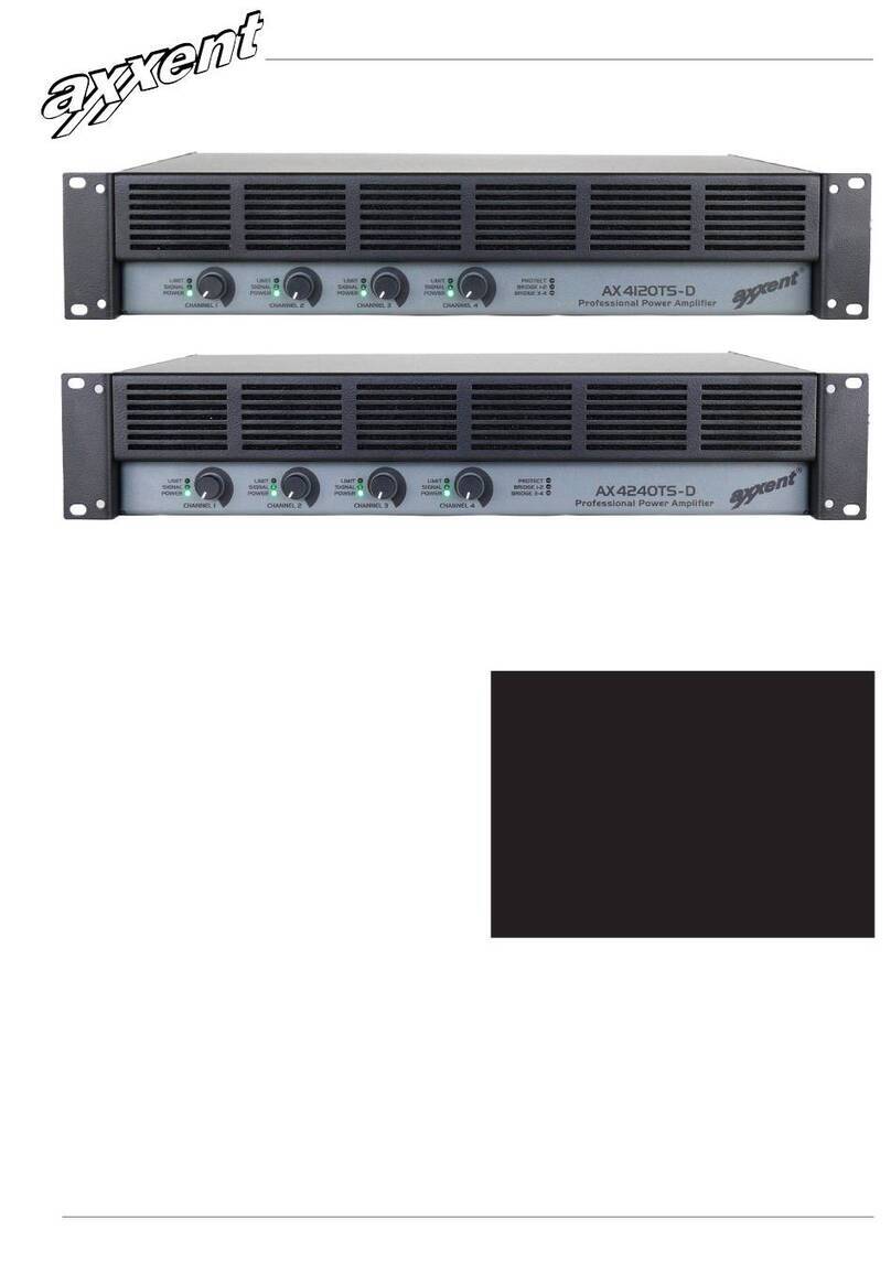
Axxent AX-4120TS-D User manual

Axxent
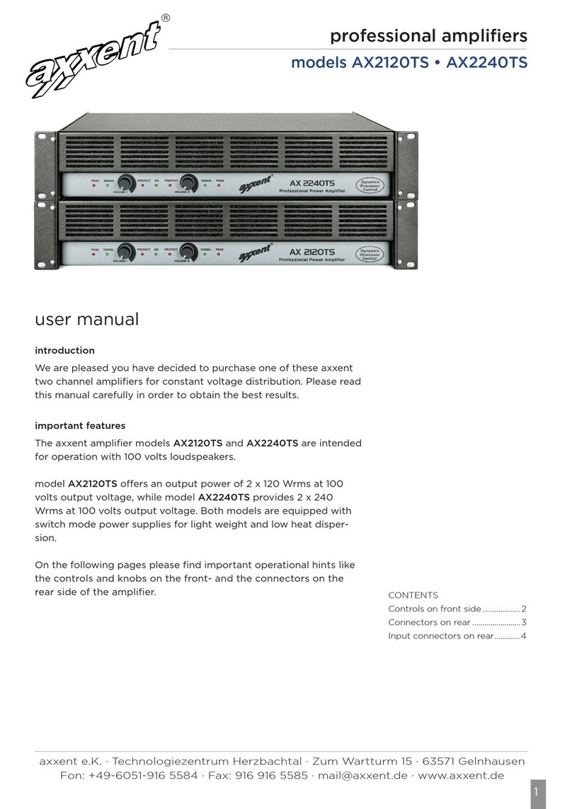
Axxent AX2120TS User manual

Axxent
Axxent AX1121TS User manual

Axxent
Axxent AX2150S User manual

Axxent
Axxent AMV-7240 MKII User manual

Axxent
Axxent CLP2090 User manual

Axxent
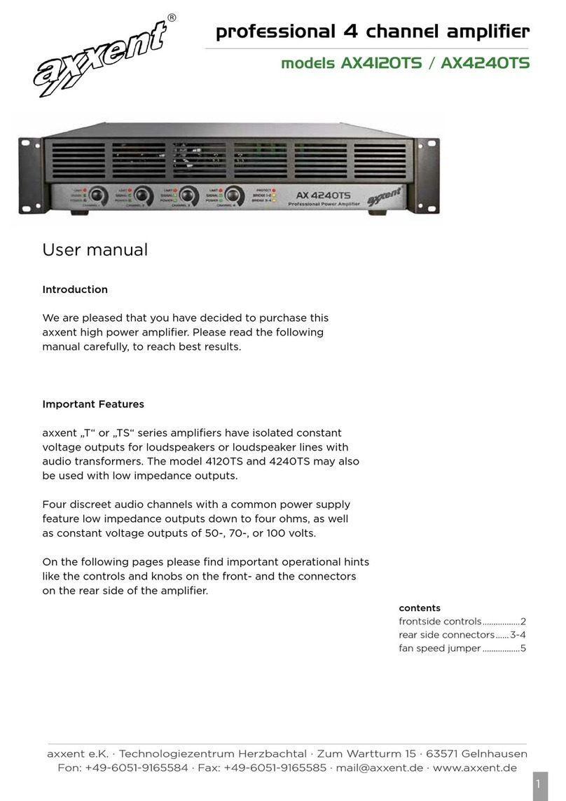
Axxent AX4120TS User manual

Axxent
Axxent AMV-7240 User manual