Aybey Elektronik UPSLIFT User manual

UPSLIFT
EMERGENCY POWER SUPPLY FOR LIFTS
USER MANUAL
Version: 1.2

1-General Description
UPSLIFT is an uninterruptable power supply designed for lift applications. It has been designed
to supply energy to the controller as well as to all peripherals such as doors, brakes, etc. in
case of any power breakdown. It does not supply any energy to the motor. Therefore, in a
system where UPSLIFT is used as emergency power supply then the motor should be fed either
by batteries or by another UPS. UPSLIFT makes use of five 12V dry batteries. It can be used in
all kinds of controllers.
2- Warning and Remarks
Read user manual before starting to install the device.
Do not connect or disconnect any wire from terminals of the device when it has been
energized.
Place the device into the controller box by leaving suggested distances around the
device according to figure 2.1. Otherwise the device may suffer from excessive heat.
Do not store and run the device in water or in excessive cold, hot, moisty and dusty
environments and where chemical gases are present. (see technical specifications)
Do not mount the device to be exposed to direct sunlight.
Figure 2.1: Recommended Mounting Distance [mm]

3- TECHNICAL SPECIFICATIONS
3.1 General Specifications
Table 3.1 Technical Specification
Nominal Output Voltage
220V AC
Max. Output Current
8 A
Max. Output Power
1800VA
DC Input Voltage
60V DC
Batteries (Number x Voltage)
5 x 12V DC
Battery Capacity
Minimum 4 Ah (See chapter 4 for selection)
Cutdown Battery Voltage
25V
Max. Input Current
30A
Maximum Storage Temperature
+70 oC
Minimum Storage Temperature
-20 oC
Maximum Operating Temperature
+70 oC
Minimum Operating Temperature
-10 oC
Standby Period
1 Hour (Resettable)
Net Weight
7.25 kg
Gross Weight
7.80 kg
!!! In case of the device is used or stored beyond the minimum and maximum ratings, then
warranty conditions are violated and permanent damage may occur.

3.2 Physical Dimensions
Table 3.2 Mechanical Dimensions [mm]
Model
H2
W
d
H1
UL180
210
180
125
170
Table 3.3 Mounting Dimensions [mm]
Model
d1
d2
d3
b1
b2
b3
a1
a2
Ø
UL180
106
190
53
10
30
18
37
13
9
Figure 3.1: Mechanical Dimensions
Figure 3.2 Mounting Dimensions

4- BATTERY AND WIRE SELECTION GUIDE
There should be 5 x 12V batteries as energy source for UPSLIFT. Battery charge capacities
should be minimum 4 Ah. However when the batteries are used at the same time as the
energy source by the traction motor, then the current taken from the batteries by the motor
should be taken into account for selecting the charge capacity of the batteries. Table 3.2 shows
the required wire cross sections and battery capacities related to the motor powers.
Table 4.1 Battery and Wire Selection Table
Traction Motor Power
Battery Charge Capacity
Battery Wire Cross-Section
4kW –5.5kW
4 Ah
2.5 mm2
5.5kW –11kW
7 Ah
4 mm2
11kW-15kW
12 Ah
4 mm2
15kW-22kW
17 Ah
6 mm2

5- ELECTRICAL CONNECTIONS
Internal blocks and terminal connections of UPSLIFT are shown in Figure 5.1 and Table 5.1.
Figure 5.1 UPSLIFT Electrical Connections
Table 5.1 UPSLIFT Terminals
Terminal
Used For
Comments
LUP
Input Phase Terminal
Line Voltage
NUP
Input Neutral Terminal
PE
Earth Connection
LP
Output Phase Terminal
Emergency controller power supply outputs
connected to the power supply input of the
controller
NP
Output Neutral Terminal
B+
Battery Pack Positive Terminal
Connected to the red terminal of the battery pack
B-
Battery Pack Negative Terminal
Connected to the black terminal of the battery pack

6- OPERATION
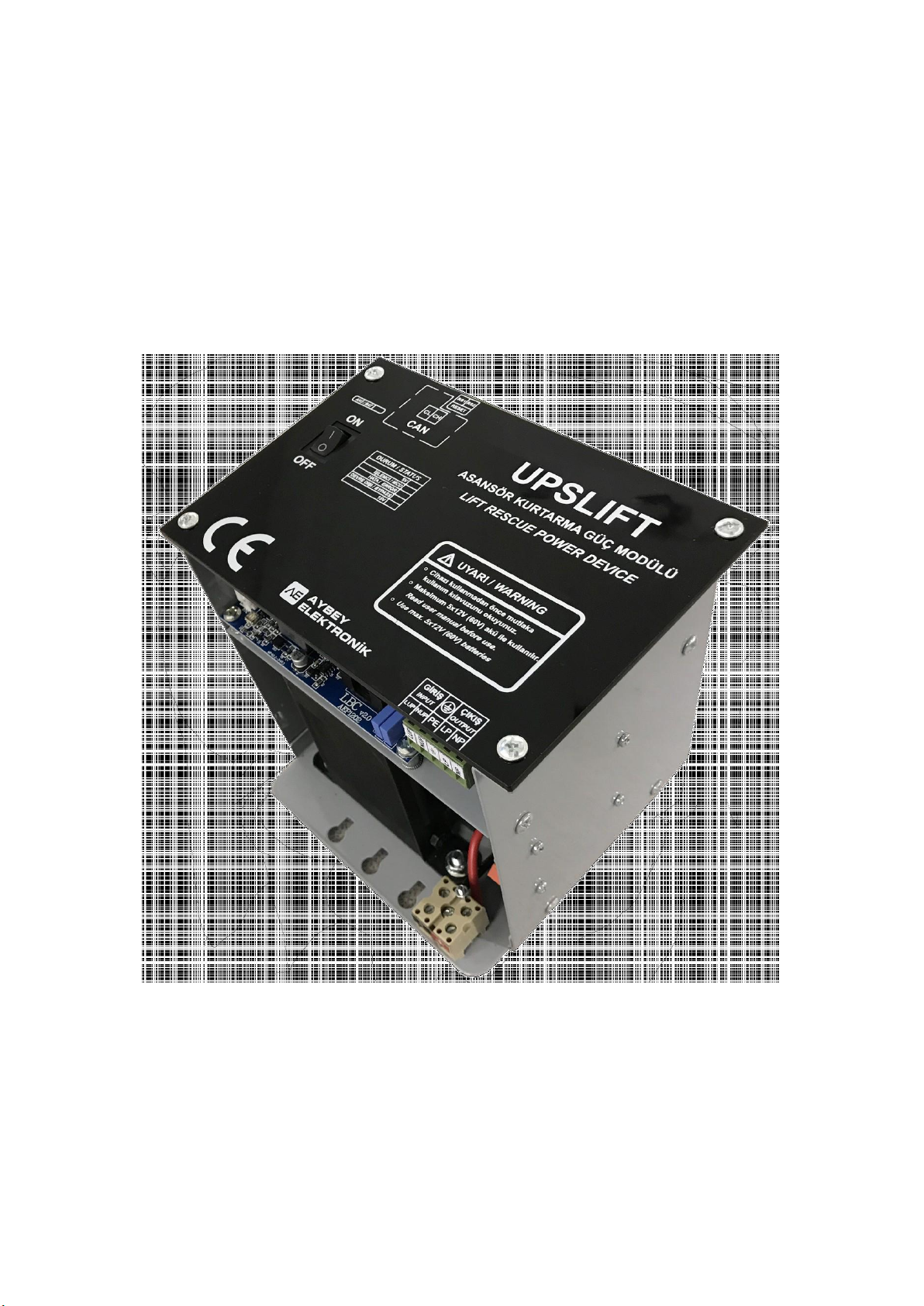
The main switch (MS in Figure 5.1) is power on/off switch of the system. When it is in ON position,
system starts to work as an emergency rescue system. If AC power is present, system bypasses AC
power input to AC output. Otherwise, system generates AC signal from battery voltage and supply AC
output. When MS is in OFF position, only battery charger unit works if AC power input is present.
The battery fuse (BF in Figure 5.1) shuts down the emergency rescue system completely by separating
the batteries from the device. Therefore it should always be in ON position when the device is used.
However when the device is not used for a while, then it is recommended to switch off BF to protect
the batteries for loosing charge.
The device has three separated group of connection terminals. They are AC power input, AC output
and battery connections. AC power input is connected to the line voltage. The batteries are charged
and do not supply any current to the system as long as the line voltage is present. In case of any power
breakdown, UPSLIFT immediately stops charging the batteries and starts to use them as energy source.
Output circuit which supplies energy to the peripherals is always active. The device keeps the output
voltage stable at 220V whatever the line condition is. The device keeps the peripherals in the shaft
unaffected in the transition period where the line power fails.
UPSLIFT will stay alive for one hour after a power breakdown. At the end of this period, it enters sleep
mode to protect the batteries from excessive discharging. However the device can be awaken at any
time when the RESET input is activated manually provided and the main switch is in ON position. It
stays one more hour alive before going to sleep mode again. So the device can be used lots of time for
a period of one hour by resetting until the batteries are getting discharged and unable to drive the
system any more.
Table 6.1 LED Indicators
Name
LED Indicator
Explanation
5V
ON
Board supply is normal.
OFF
Board supply is off.
MCU
ON
System is powered but the microcontroller is not working.
OFF
System is not working.
Blinking
System is working normally.
ERROR
ON
There is an error.
OFF
No errors.
BYPASS
ON
Line voltage is connected directly to the output circuit. UPSLIFT is not
active.
OFF
Output voltage is generated by UPSLIFT.
15V
ON
Internal 15V is present.
OFF
Internal 15V failed.
BAT
ON
Batteries are connected to the device.
OFF
Batteries are not connected or battery fuse is off.

7- TROUBLESHOOTING
Table 7.1 shows some comments about common reported problems.
Table 7.1: Possible Errors and Solutions
NO
PROBLEM
COMMENTS
1
There is no output voltage
in rescue operation
Check MS (main switch) switch. It must be ON.
Check if the batteries are connected correctly.
Check 5V LED, it should be blinking. If not there may be a
fault in electronic board.
Check 15V LED, it should be ON. If not there may be a fault
in electronic board.
Check the BF (battery fuse). It must be present, not broken.
2
There is no output voltage
in normal operation
Check LUP-NUP terminals. There should be an input voltage
at 220V / 230V AC.
3
Batteries are not charging
Check the BF (battery fuse). It must be present not broken.
Check that the batteries are connected correctly.
4
5V led is always on
Restart system and if led remain same, the electronic board
may have a fault.
5
5V led is always off
Check If MS (main switch) switch is ON.
Check if the batteries are connected correctly.
If all are OK then the electronic board may have a fault.
This manual suits for next models
1
Table of contents